

Elgama G1B Series, GAMA 100 User Manual

Static electricity meter
GAMA 100
G1B.xxx
User manual
Version 2.3b
(G1BEN23b)
“ELGAMA – ELEKTRONIKA” Ltd., Lithuania 2016


“ELGAMA-ELEKTRONIKA”
Static electricity meter
GAMA 100
G1B.xxx
USER MANUAL
"ELGAMA-ELEKTRONIKA" Ltd.
2 Visorių str.
LT-08300 Vilnius
Ph.: +370 5 2375000
Fax: +370 5 2375020
E-mail: info@elgama.eu
REVISION HISTORY
Version Date Comments
1.0 2010-07-19 First release
1.1 2010-09-20 Information update
1.2 2011-09-01 Description of functional possibility added (Internal mains Relay, Shunt and
RS485 interface)
1.3 2012-01-04 Synchronization of internal clock (RTC) and control algorithm of internal
main relay was added
1.4 2012-05-14 Description of functional possibility added (current measurement in neutral
and Wired M-Bus interface was added)
1.5 2012-11-12 Control algorithm of Internal main relay by specified time and date, and by
current over limit was added. Encryption and Authentication.
2.0 2014-03-07 Description of internal PLC modem and firmware upgrade functionality was
added.
2.1 2014-04-29 Description of internal PRIME PLC modem (modification H2) and firmware
upgrade functionality was added.
2.2 2015-03-04 Tariff program update. LCD list updated and removed inaccessible
features. Bi-stable internal relay functionality updated.
2.2a 2015-04-18 New modification of optional LCD was added. Wireless M-Bus was added.
2.2b 2015-08-21 Description of internal PLC modem (modifications H3, H4), THD
measurement and Second Load Profile (Network profile) was added
2.3a 2015-08-25 DLMS/COSEM protocol Logical name (LN) referencing, non-transparent
meter case and Extended LCD was added
2.3b 2016-03-04 Information about power consumption of meter with external power supply
for modem was added. Bi-stable internal relay functionality updated.
Wireless MBus interface was added. Meter status on LCD update

S
TATIC ELECTRICITY METER
GAMA 100. U
SER MANUAL
Contents
Contents .................................................................................................................................................................. 5
About this document ................................................................................................................................................ 8
1 Safety .............................................................................................................................................................. 8
1.1
Safety requirements ............................................................................................................................... 8
1.2
Transportation and storage rules ........................................................................................................... 8
1.3
Prevention and elimination of malfunctions............................................................................................ 9
1.3.1 Exterior inspection ............................................................................................................................. 9
1.3.2 Inspection of connection and parametrization constants ................................................................... 9
1.3.3 Procedure of meter returning to manufacturer ................................................................................... 9
1.3.4 Proper disposal of product ................................................................................................................. 9
2 Designation ...................................................................................................................................................10
3 Meter modifications .......................................................................................................................................11
3.1
Modifications ........................................................................................................................................11
3.2
Technical specifications .......................................................................................................................11
4 Functional possibilities ..................................................................................................................................12
4.1
Current, voltage, frequency ..................................................................................................................12
4.2
Additional functions ..............................................................................................................................13
4.3
Sealed button functions ........................................................................................................................13
4.4
Backup power source ...........................................................................................................................14
4.5
Communication, inputs/outputs ............................................................................................................14
4.6
Voltage and current circuit separation ..................................................................................................15
4.7
Internal bi-stable mains Relay ..............................................................................................................15
4.8
LCD options ..........................................................................................................................................15
4.9
Internal PLC modem ............................................................................................................................15
5 Construction ..................................................................................................................................................16
5.1
Case .....................................................................................................................................................16
5.2
Nameplate ............................................................................................................................................16
5.3
Terminal block ......................................................................................................................................17
5.4
Operation principle ...............................................................................................................................18
5.4.1 Measurement module ......................................................................................................................18
5.4.2 Signal conversion .............................................................................................................................18
5.4.3 Micro-controller ................................................................................................................................18
5.4.4 Non-volatile memory ........................................................................................................................18
5.5
Display (LCD) .......................................................................................................................................18
5.5.1 Default LCD (Option #1) ..................................................................................................................19
5.5.2 Optional LCD (Option #2) ................................................................................................................20
5.5.3 Extended LCD (Option #3) ...............................................................................................................21
5.6
Internal clock ........................................................................................................................................22
5.6.1 Synchronization of internal clock (RTC) ..........................................................................................22
5.7
Sliding voltage link ................................................................................................................................23
6 Communication .............................................................................................................................................23
6.1
Optical communication interface ..........................................................................................................23
6.2
Electrical interface ................................................................................................................................23
6.3
Controller MCL 5.XX with internal GSM/GPRS modem ......................................................................24
6.4
PLC modem .........................................................................................................................................25
6.4.1 Internal PLC modem ........................................................................................................................26
6.5
Wired M-Bus module ............................................................................................................................26
6.6
Wireless M-Bus interface .....................................................................................................................27
6.7
Plug & Play ...........................................................................................................................................27
6.8
Outputs/Inputs ......................................................................................................................................27
6.8.1 Optical test output (red LED) ...........................................................................................................27
6.8.2 S0 outputs ........................................................................................................................................27
6.8.3 Relay output .....................................................................................................................................27
6.9
Power supply ........................................................................................................................................28
6.9.1 Power supply for external modem ...................................................................................................28
6.10 Push buttons ........................................................................................................................................28
6.10.1
Scroll push button and optical scroll key .....................................................................................28
6.10.2
Sealed push-button .....................................................................................................................29
7 Data registers ................................................................................................................................................29
7.1
Energy registers ...................................................................................................................................29
7.2
Demand registers .................................................................................................................................30
5

7.3
Maximum demand registers .................................................................................................................31
8 Data profiles ..................................................................................................................................................31
8.1
Billing profile .........................................................................................................................................31
8.2
Load profile ...........................................................................................................................................33
8.3
Second load profile ...............................................................................................................................34
8.4
Wired M-Bus load profile ......................................................................................................................34
8.5
Event log...............................................................................................................................................34
8.5.1 Power failure (outage) event log ......................................................................................................35
8.5.2 Voltage swell (over-voltage) event log .............................................................................................35
8.5.3 Voltage sag (under-voltage) event log .............................................................................................35
8.5.4 Event log of internal mains relay ......................................................................................................35
8.5.5 Power over-limit event log ................................................................................................................36
8.5.6 Reverse current flow event log ........................................................................................................36
8.5.7 Over-current event log .....................................................................................................................36
8.5.8 Neutral current balance event log ....................................................................................................37
8.5.9 Magnetic field influence event log ....................................................................................................37
8.5.10
Opening of meter cover event log ...............................................................................................37
8.5.11
Opening of terminal cover event log ............................................................................................37
8.5.12
Clock change (setting) event log .................................................................................................37
8.5.13
Parameterisation (Parameter change) event log .........................................................................38
8.5.14
Security failure (failed authentication) log ...................................................................................38
8.5.15
Meter (internal) error event log ....................................................................................................39
8.5.16
Tariffs event log ...........................................................................................................................39
8.5.17
Load profiles reset log .................................................................................................................39
8.5.18
Firmware update event log ..........................................................................................................39
9 Data monitors ................................................................................................................................................39
9.1
Demand monitor ...................................................................................................................................39
9.2
Current monitor ....................................................................................................................................40
9.3
Over-voltage monitor ............................................................................................................................41
9.4
Under-voltage monitor ..........................................................................................................................41
10 Tariff program ................................................................................................................................................42
10.1 Day tariff programs ...............................................................................................................................42
10.2 Week tariff program ..............................................................................................................................43
10.3 Tariff seasons .......................................................................................................................................43
10.4 List of special days ...............................................................................................................................43
10.5 “Emergency” tariff .................................................................................................................................44
10.6 Tariff timers ..........................................................................................................................................44
11 Data reading ..................................................................................................................................................44
11.1 Reserved-automatic (RA) display sequence ........................................................................................47
11.2 Main automatic (MA) display sequence ...............................................................................................48
11.3 Main manual (MM) display sequence ..................................................................................................48
11.4 Indication of abnormal states on LCD ..................................................................................................48
11.4.1
Internal meter errors ....................................................................................................................48
11.5 Data reading via communication interfaces .........................................................................................49
12 Parametrization .............................................................................................................................................49
13 Data protection ..............................................................................................................................................51
13.1 Physical protection ...............................................................................................................................51
13.2 Software protection ..............................................................................................................................51
13.2.1
Data access security ...................................................................................................................51
13.2.2
Passwords ...................................................................................................................................51
13.2.3
Encryption and Authentication .....................................................................................................52
13.2.4
Firmware/hardware identifiers .....................................................................................................52
13.2.5
User’s identifiers ..........................................................................................................................52
13.2.6
Blocking of optical communication interface ...............................................................................52
13.2.7
Parameterization ID .....................................................................................................................53
13.2.8
Event log, security alerts .............................................................................................................53
13.3 Firmware upgrade ................................................................................................................................53
14 Internal bi-stable main relay ..........................................................................................................................54
14.1 Action “disconnect by remote control command” .................................................................................55
14.2 Action “disconnect by contractual power exceeded” ............................................................................55
14.3 Action “disconnect by phase current limit exceeded” ...........................................................................56
14.4 Action “disconnect by swings of network voltage” ...............................................................................57
14.5 Action “allow to connect by remote control command” ........................................................................58
6

14.6 Action “allow to connect by end of billing period” .................................................................................58
14.7 Action “allow to connect by end of event” ............................................................................................59
14.8 Action “connect by Menu button” .........................................................................................................59
14.9 Action “connect by the mains switch of the internal electrical installation” ..........................................59
15 Installation .....................................................................................................................................................60
Annex A. Dimensions of the meter ........................................................................................................................61
Annex B. Screw torques used in G1B meters .......................................................................................................62
Annex C. List of data objects .................................................................................................................................63
7

About this document
This User Manual presents a description of a static electricity meter GAMA 100 (G1B.xxx)
and its instruction. Please read this instruction prior to the use of the meter. The
manufacturer does not give any guaranty in case meter is damaged during the exploitation
that contravenes with the instructions and requirements of safety stated in the manual and
meter passport.
The manufacturer is not responsible for the loss in case the meter is parameterized without
accordance with the instructions and recommendations presented in the software description
as well as with tariff order defined by the State. It does not carry the responsibility for the
unprofessional acts of responsible persons in case of full or partial loss of billing data.
User manual presents the description of all possible characteristics, functions and auxiliary
outputs of electricity meter. A concrete meter may not comply with all characteristics
introduced in this manual; however, meter passport defines a precise meter configuration,
possibilities and auxiliary outputs as well as a concrete connection scheme.
The manufacturer has a right to change the information presented in this manual without the
warning. In addition, any copying, transmission and publication of full or partial meter
documentation is forbidden without a written permission of “ELGAMA-ELEKTRONIKA” Ltd.
1 Safety
1.1 Safety requirements
1. Installing, uninstalling, parameterization and verification can be performed only by
authorized organizations that have qualified technicians. Only qualified persons should
install meters.
2. Meter’s connection or disconnection from network should be done when voltage in the
network is turned off. A protection from accidental network voltage connection must be
established.
3. No accessories can be hung on a meter, it is forbidden to hit or strike meter’s case.
4. Precautions must be taken in battery changing procedure: 1) meter has to be
disconnected from electricity network, a protection from accidental network voltage
connection must be assured; 2) use pincers or similar instruments to change battery
(connection/disconnection of a plug).
1.2 Transportation and storage rules
1. Prior to the usage meter must be kept in a closed room in a transportation packing,
where the temperature ranges from 5°C to 40°C and average area humidity is up to
80% when temperature being 25°C. The room must be without harmful gas or steam.
Meter must be kept and exploited in premises protected from dust, aggressive vapors
and gas.
2. Unpacked meters can be kept only in repair workshop. The temperature must range
from 10°C to 35°C, average area humidity must not exceed 80% when temperature
being 25°C.
3. During wintertime meters must be kept in a heated room for 6 hours or more, before
they are used.
4. Meters are to be transported only in closed vehicles (carriage, container, hold). Shake
acceleration is to be up to 30m/s², 80-120 strikes per minute. The temperature must
range from -40°C to +70°C, average area humidity must not exceed 98% when
temperature being 35°C.
8
1.3 Prevention and elimination of malfunctions
If suspected that meter works improperly, the following actions should be performed:
1.3.1 Exterior inspection
Before applying voltage to the meter makes sure its case has no mechanical damages, there
are no signs of overheating, and all wires are properly connected.
Do not plug a meter into network if it is mechanically damaged. This can cause
staff injuries and destroy meter as well as other equipment!
Before switching on network voltage, it is necessary to check if sliding voltage
link is connected (see chapter 5.7 Sliding voltage link).
1.3.2 Inspection of connection and parametrization constants
Installing, uninstalling, parametrization and verification can be performed only by authorized
organizations that have qualified technicians. After plugging a meter into electric network
technician should check whether date and time are correct, whether meter shows right
energy direction, valid tariff time zone and calendar, tariff seasons.
1. If meter shows wrong date and time, a representative from the organization in charge of
the meter installation should be informed.
2. If LCD indicator shows a warning note ‘Er’, the meter should be uninstalled and passed
for repair works.
3. If energy direction is wrong, technician should check whether inputs are connected
properly to terminal block.
4. If meter calendar season, season time name or valid tariff time zone does not correspond
to real situation, meter’s parameterization data has to be checked and errors has to be
corrected by repeated meter’s parameterization.
1.3.3 Procedure of meter returning to manufacturer
In case malfunctions cannot be eliminated on the spot, the meter should be returned to the
manufacturer for repair or replacement. Meters on their return to manufacturer must have
their Passport with notices of organization in charge of their exploitation and short description
of meter’s malfunctioning.
1.3.4 Proper disposal of product
This sign indicates, that this product cannot be thrown out with any other
waste when its validity period is over if this sign is on the product or it is
included in product’s description. In order to prohibit possible harm for
environment and human health because of uncontrolled waste
elimination, please separate this product from other forms of waste, and
if it is possible use this product or its parts repeatedly in recycling
process. Home users can contact product manufacturer or local
administration for information about product utilization and recycling
without any harm to the environment. Enterprises must contact their own
providers to revise product’s validity terms and conditions stated in
purchase agreements. This product cannot be thrown out with any other
waste of different kind.
9

2 Designation
The static meter of direct connection GAMA 100 (G1B.xxx) is designated for measurement of
active or active and reactive electrical energy in alternate current networks. G1B meters can
measure active energy in both directions (+A and –A, as well as |A|) simultaneously and measure
reactive energy in directions (+R and -R), as well as in four quadrants (R1, R2, R3, R4)
simultaneously.
G1B.xxx meters can register maximum demand on daily and monthly bases, measure
instantaneous values as well as record load profile and event log.
Meters can be either single-rate or multi-rate. The rates are controlled by internal real-time clock.
G1B.xxx meters have S0 output(s) and optionally can have optical and electrical communication
interfaces for local and remote data transmission.
Meter G1B.xxx conforms to the following requirements of directives and standards:
- Directive 2004/22/EC of the European Parliament and of the Council of 31 March 2004 on
measuring instruments;
- Directive 2004/108/EC of the European Parliament and of the Council of 15 December 2004
on the approximation of the laws of the Member States relating to electromagnetic
compatibility and repealing Directive 89/336/EEC;
- EN 50470-3:2006 “Electricity metering equipment (a.c.) – Static meters for active energy
(class indexes A, B and C)”;
- EN 50470-1:2006 “Electricity metering equipment (a.c.) – General requirements, tests and
test conditions – Metering equipment (class indexes A, B and C)”;
- IEC 62053-21:2003 “Electricity metering equipment (a.c.) – Static meters for active energy
(classes 1 and 2)”;
- IEC 62053-23:2003 “Electricity metering equipment (a.c.) – Static meters for reactive
energy (classes 2 and 3)”;
- IEC 62052-11:2003 “Electricity metering equipment (a.c.) – General requirements, tests and
test conditions. Part 11: Metering equipment”;
- IEC 62052-21:2003 “Electricity metering equipment (a.c.) – General requirements, tests and
test conditions. Part 21: Tariff and load control equipment”;
- IEC 62054-21:2004 “Electricity metering equipment (a.c.) – Tariff and load control. Part 21:
Particular requirements for time switches”;
- IEC 62056-21:2002 “Electricity metering – Data exchange for meter reading, tariff and load
control. Part 21: Direct local data exchange”;
- IEC 529 “Degrees of protection provided by enclosures”
- IEC 61334-4-41 “Distribution automation using distribution line carrier systems – Part 4:
Data communication protocols – Distribution line message specification”
- IEC 62056-46 Data link layer using HDLC protocol;
- IEC 62056-53 DLMS/COSEM Application Layer;
- IEC 62056-61 DLMS/COSEM Obis code;
- IEC 62056-62 DLMS/COSEM Interface Classes.
- EN 13757-2:2005 Communication systems for and remote reading of meters - Part 2:
Physical and link layer;
- EN 13757-3:2005 Communication systems for and remote reading of meters - Part 3:
Dedicated application layer;
- EN 50065-1 Signalling on low-voltage electrical installations in the frequency range 3 kHz to
148,5 kHz -- Part 1: General requirements, frequency bands and electromagnetic
disturbances.
Note: Tables and Figures in this User manual may present measurement values and pulse outputs
in all possible energy and power directions. Actual number of measured values and pulse outputs
of a certain meter modification are indicated in meter passport.
10
XXX.
X
1 X
5 X
Accuracy class:
Reference voltage U
, V:
Operating voltage range, % from U
:
Reference I
(maximum I
) current, A:
Starting current, % from I
:
Reference frequency, Hz:
Power consumption, VA:
Meter constant, imp/kWh, imp/kva
rh:
Internal clock (IEC 62
052-21
, IEC 62054
-21):
Tariff module functions:
S0 outputs (IEC 62053
-
31):
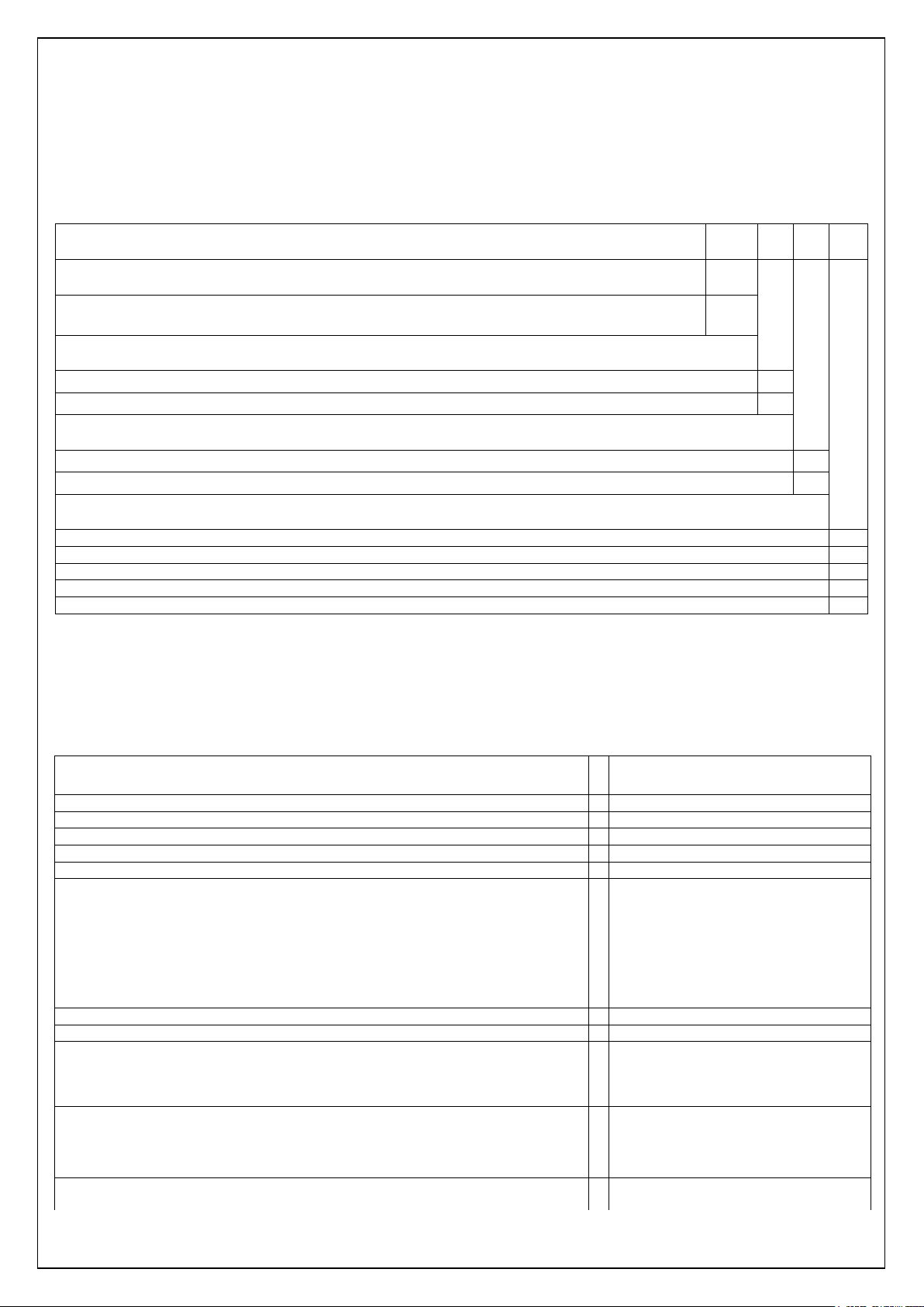
3 Meter modifications
3.1 Modifications
Meter G1B is multi-tariff meter (measures active and reactive energy).
Detailed explanation of meter modification is presented in Table 3-1.
Table 3-1 GAMA 100 meter modifications
Type explanation example:
Construction
G1B (LCD, multi-tariff, active energy or active and reactive energy, max demand, extended
functionality)
Accuracy class
A (EN 50470-3), 2.0 (IEC 62053-21) 0
B (EN 50470-3), 1.0 (IEC 62053-21) 1
Measurement circuits
1 elements, 2 wire 5
2 elements (current measurement in neutral), 2 wire 6
In/Imax, Iref/Imax
1:8 0
1:10 1
1:12 2
1:16 3
1:20 4
G1B.
G1B
2
Example: G1B.152 is G1B construction meter that conforms to the requirements of accuracy class B and 1.0. Meter is
designated for measurement of energy in 2 wire alternate current networks; it has 1 measurement element. It is directconnected meter with maximum current up to 60 A. Ratio of reference current and maximum current is 1:12.
3.2 Technical specifications
Table 3-2 Technical specifications
n
ref
Operation duration using only backup power supply (Li-ion battery) > 10 years
max
ref
Active energy measurement B (EN 50470-3), 1.0 (IEC 62053-21)
Reactive energy measurement 2.0 (IEC 62053-23)
n
In voltage circuits <1.0 VA (<0.5 W)
In current circuits < 0,05
Error < 0,5 s/24 h (T=23°C),
Backup power supply for clock Li-ion battery and/or supercapacitor
Number of energy tariffs Programmable (T1 T6)
“Emergency” tariff Programmable (T1 T6)
Number of maximum demand tariffs Programmable (M1 M6)
Data storage duration when voltage disconnected
Number 1
Output constant, imp/kWh (imp/kvarh) 50150000
See Table 4-2
-20... +15
See Table 3-1 and Table 4-2
0,4 (class B)
50
<4.0 VA (<1.3 W) with +5V power
supply for external modem
<10 VA (<1.0 W) with PLC module
<10 VA (<1.3 W) with PLC and wired
MBus modules
<10 VA (<2.2 W) with PLC and wireless
MBus modules
50150000
< 0,15 s/°C/24 h
>20 years
11
Relay output:
Internal mains relay:
Communication interfaces:
Isolation:
Magnetic field sensiti
vity
Protection against dust and water
Temperature range:
Mass, kg:
Dimensions, mm
Average service life
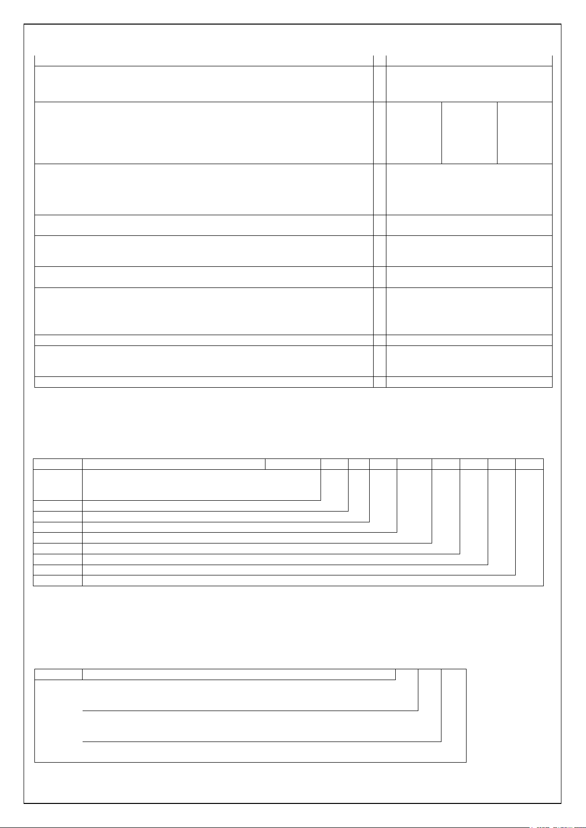
Code:
X X X.
FXX.
BX. PX. CXXX.
VX. RX. LX. HX
Reference current
Reference voltage
Reference frequency
F -
additional Functions
B -
sealed Button functions
P -
backup Power source
C -
Communication, I/O
V -
voltage and current circuit separation
R -
internal main relay
L -
LCD options
H –
internal PLC modem
Code:
X X X.
Reference current
Reference voltage
Reference frequency
Pulse duration, ms 30
Programmable (1 2)
Maximum commutation voltage, V 250
Maximum commutation current, mA 120
Bi-stable
Max switching current (Imax)
Max switching voltage (115% Unom)
Max switching power (1.15×Unom×Imax)
Mechanical endurance
Electrical endurance
Optical interface IEC 62056-21, DLMS/COSEM
Electrical interface – CL (20mA current loop) IEC 62056-21, DLMS/COSEM
RS485 IEC 62056-21, DLMS/COSEM
Wired M-Bus/ Wireless M-Bus EN 13757-2; EN 13757-3
Pulse voltage tests (IEC 60060-1) 6 kV (1,2/50 µs)
Alternating voltage tests 4 kV @ 50 Hz, 1 minute
Immunity against permanent magnetic fields
Immunity against electromagnetic HF fields
Operation:
For meters with battery and for meters without power backup source
For meters with supercapacitor
Storage, transportation: - 40 +70°C
with usual terminal cover
with special terminal cover for GSM/GPRS modem
Option #1 Option #2 Option #3
≤ 40A
≤265 V
≤10,6 kW
1×10⁵
5×10³
PLC EN 50065-1 (CENELEC A (3–95 kHz))
> 3.5 mT
≤ 300 mT (current sensor – shunt)
≤ 30 V/m (80 - 2000 MHz)
IP53 default
IP54 (optional)
- 40 +70°C (3K7)
- 25 +70°C
< 0,9
180 x 130 x 65 (see Figure A-0-1)
200 x 130 x 80 (see Figure A-0-2)
16 years
≤ 80A
≤265 V
≤21,2 kW
1×10⁵
5×10³
≤ 100A
≤265 V
≤26,5 kW
1×10⁵
5×10³
4 Functional possibilities
G1B meters can have different functional possibilities which are described below.
Table 4-1 Ordering code
Section No.
1
2
3
4
5
6
7
8
9
4.1 Current, voltage, frequency
G1B meters may differ in current, voltage and frequency. Choices are denoted with the first three
digits in ordering code and are listed in Table 4-2.
Table 4-2 Possible code choices for current, voltage and frequency
No.
Section 1
5 A 2
10 A 3
100 V, 120 V, 127 V 1
220 V, 230 V, 240 V 2
50 Hz 0
See chapter 4.1
See chapter 4.1
See chapter 4.1
See chapter 4.2
See chapter 4.3
See chapter 4.4
See chapter 4.5
See chapter 4.7
See chapter 4.8
See chapter 4.9
See chapter 4.6
12

F -
Energy measurement, instantaneous values, loa
d profiles
Code:
FX X.
Energy measurement
F3
F4
DLMS/COSEM protocol
-
8
B-sealed Button functions
Code:
BX.
4.2 Additional functions
Along with unidirectional and bidirectional active energies, G1B meters may measure reactive
energy and maximum demand, store registers of up to 16 billing periods in billing profile, measure
instantaneous values and record load profile. Choices for energy measurement and programmable
functions are denoted with letter “F” and two digits in ordering code and are listed in Table 4-3.
Table 4-3 Possible code choices for energy measurement, instantaneous values and load profiles
No.
Section 2
Billing and load profile, instantaneous values and maximum demand
Billing and load profile, instantaneous values and maximum demand, reactive energy
Short name (SN) referencing
Logical name (LN) referencing
Table 4-4 List of instantaneous values.
12.7.0 Instantaneous RMS voltage (V)
11.7.0 Instantaneous RMS current (A) in phase
15.7.0
16.7.0 Instantaneous active power ±P (kW)
3.7.0 Instantaneous reactive power +Q (kvar)
4.7.0 Instantaneous reactive power –Q (kvar)
13.7.0
14.7.0 Frequency (Hz)
91.7.0 Instantaneous RMS current (A) in neutral
12.7.124 Instantaneous THD for voltage
11.7.124 Instantaneous THD for current
Harmonics analysis is performed by using a digital band-pass filter, tuned to 50 Hz (narrow band).
Total Harmonic Distortion (THD) for current and voltage is calculated by formulas:
Wide band RMS values are measured up to 21st harmonics (21 × 50 Hz = 1050 Hz).
Maximum demand registration is explained in chapter 7.3. For more information about billing
profile refer to chapter 8.1. List of measured instantaneous values is presented in Table 4-4.
Instantaneous data can be readout via all available communication interfaces.
Please note: meters that do not contain reactive energy registers (Code F3), do not measure
instantaneous reactive power, as well as power factor cos(φ). For more information about load
profile refer to chapter 8.2.
Instantaneous active power |P| (kW)
cos ϕ
THD−=
I
22
II
NBWB
2
I
NB
THD−=
U
U
2
NB
22
UU
NBWB
IWB – RMS value of current, measured in wide frequency band;
INB – RMS value of current, measured in narrow frequency band (50 Hz);
UWB – RMS value of voltage, measured in wide frequency band;
UNB – RMS value of voltage, measured in narrow frequency band (50 Hz).
The sample rate is Fs = 2184.53 Hz (32768 Hz/15).
4.3 Sealed button functions
G1B meters may have sealed button, which may perform one of the functions described below.
Choices of sealed button functions are denoted with letter “B” and one digit in ordering code and
are listed in Table 4-5. More about button functions in chapter 6.10.2.
Table 4-5 Possible code choices for sealed button functions
No.
Section 3 Without Billing period reset B1
Communication unblock for parameterization B2
Billing period reset and communication unblock for parameterization B4
13

No. P -
backup Power source
Code:
PX.
C -
Communication, I/O
Code:
CX X X.
Optical and
electrical interfaces
Outputs/inputs
Control outputs
4.4 Backup power source
G1B meters may have different backup power sources. Backup power source choices are denoted
with letter “P” and one digit in ordering code and are listed in Table 4-6.
Table 4-6 Possible code choices for backup power source
Section 4 Without
Supercapacitor
Unchangeable battery
Changeable battery P3
Changeable battery and supercapacitor P4
Unchangeable battery and supercapacitor P5
P1
P2
Unchangeable battery is mounted on the top right corner of the PCB. Changeable battery is
mounted on the top right corner of the meter under the sealable battery cover and under silicone
protection. Battery cover with sealing option is available on the top right corner of both meters with
changeable and with unchangeable meter. Sealed button is placed under the cover. It is
accessible only when battery cover is opened.
Changing of battery:
• Ensure conditions for meter LCD to be turned-off (do not push scroll button or do not allow
to pass light to optical scroll key);
• Open changeable battery cover and remove silicone protection;
• Make ready new battery for old battery’s replacement;
• Disconnect old battery’s connector, remove the battery;
• Place new battery into old one’s location and connect plug to the corresponding meter
socket;
• Put in silicone protection and close the battery cover;
• After pushing scroll button, meter must display data. Appearance of data is a sign of correct
battery changing process.
4.5 Communication, inputs/outputs
G1B meters may have optical (see chapter 6.1) and electrical interfaces (see chapter 6.2). Meters may
have S0 outputs for transmission of information about measured energy (see chapter 6.8.2). G1B
meters may also have relay output (see chapter 6.8.3). Choices of communications, inputs/outputs are
denoted with letter “C” and three digits in ordering code and are listed in Table 4-7.
Table 4-7 Possible code choices for communications, inputs/outputs
No.
Section 5
Without interfaces C0
Optical interface C1
Optical and 20 mA “current loop” interface C2
Optical and RS485 interface C3
Optical, RS485 and M-Bus C6
Optical, M-Bus and RS485 (PLC duplication) C7
Optical and wireless M-Bus (868 MHz) C9
Optical and wireless M-Bus (169 MHz) CA
Optical and USB host CB
Without 0
S0 out (A) 1
Without
Relay output 1
Two relay outputs 2
0
14
V -
voltage and current circuit separation
Code:
VX.
R -
internal bi
-
stable mains relay
Code:
RX.
L -
LCD options
Code:
LX.
H –
Internal PLC modem
Code:
HX
4.6 Voltage and current circuit separation
G1B meters may be manufactured with or without voltage and current circuit separation. Choices
of circuit separation denoted with letter “V” and one digit in ordering code and are listed in Table
4-8.
Table 4-8 Possible code choices for circuit separation
No.
Section 6 The voltage and current circuits separated by sliding voltage link The voltage and current circuit not separated V1
4.7 Internal bi-stable mains Relay
G1B meters may be manufactured with or without internal mains relays. Choices of internal mains
relay are denoted with letter “R” and one digit in ordering code and are listed in Table 4-9. More
information about internal main relay is in chapter 14.
Table 4-9 Possible code choices for internal main relay
No.
Section 7 Without relay With relay R1
4.8 LCD options
G1B meters may be manufactured with or without function of LCD backlight. Backlight of LCD can
be switched on and turned off by locally and remotely. Choices of LCD options are denoted with
letter “L” and one digit in ordering code and are listed in Table 4-10. Optional LCD display supports
indication of up to 6 (six) tariffs. Extended LCD displays OBIS code by means of 6 symbols, while
default LCD and optional LCD possess only 4 symbols for LCD (see chapter Error! Reference
source not found.).
Table 4-10. Possible code choices for LCD options
No.
Section 8 (LCD Option #1) Default LCD (4 tariffs, 4 symbols for OBIS code) (LCD Option #1) Default LCD with backlight L1
(LCD Option #2) Optional LCD (6 tariffs, 4 symbols for OBIS code) L2
(LCD Option #2) Optional LCD with backlight L3
(LCD Option #3) Extended LCD (4 tariffs, 6 symbols for OBIS code) L4
(LCD Option #3) Extended LCD with backlight L5
4.9 Internal PLC modem
G1B meters may be manufactured with or without internal PLC modem. Choices of internal PLC
modem are denoted by letter “H” and one digit in ordering code, and are listed in Table 4-11. See
chapter 6.4 for further details.
Table 4-11. Possible code choices for internal PLC modem
No.
Section 9 Without internal PLC modem -
With internal PLC modem (DCSK modulation) H1
With internal PLC modem (PRIME) H2
With internal PLC modem (PRIME) and RS485 (PLC duplication) H3
With internal PLC modem (G3) and RS485 (PLC duplication) H4
NOTE: If an option with character “-” is chosen, that function will not be included in the ordering
code.
15
1
6
2
7
3
8
4
9
5
10
5 Construction
5.1 Case
Meter case, fixing holes and terminal block conform to the requirements of standard DIN 43857.
Meter case can be made from transparent highly mechanically resistant and fire retardant
insulation material – polycarbonate, stabilized by ultraviolet rays or molded of non-transparent
polycarbonate with transparent polycarbonate windows for LCD, optical interface and optical test
output. It protects meter interior parts and its nameplate. Main cover (transparent and nontransparent parts of main cover) is fixed to the base by two sealing screws. Removal of main cover
of mounted meter could be done only after terminal cover removal. An option of special sealing
bolts preventing disassemble of meter is available. Terminal cover is fastened with 1 sealing screw
(suspended seal). Access to the terminals without terminal cover removal is excluded. This affords
additional level of security to the customer. Terminal cover has a hole for threading sealing wire to
sealing screw. The possibility to touch the meter terminals with sealing wire while sealing the
terminal cover is prevented.
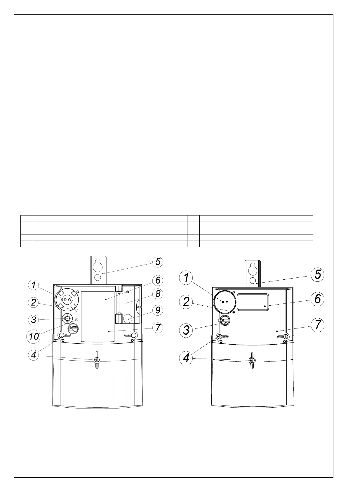
Figure (See Figure 5-1) presents meter exterior parts and allotment of control elements. For case
dimensions and allotment of fixing holes see Figure A-0-1.
There is a liquid crystal display (LCD), optical communication interface, optical scroll key for
display control, sealable and not sealable buttons on the main cover of the meter. See chapter 11
for the explanation of display control commands, and chapter 6.10 for the description of push
buttons.
Table 5-1 Explanation of Figure
Optical Interface
Optical test output [imp/kWh]
Scroll push-button or Multifunctional (two-position) button
Sealing screws of main cover and terminal cover
Eyelet
LCD
Nameplate
Changeable battery cover
Sealed push-button
Status indicator (LED) of internal mains relay
Figure 5-1 G1B meter exterior view with transparent cover Figure 5-2 G1B meter exterior view with non-transparent cover
5.2 Nameplate
Nameplate for meter, with transparent cover, is printed on plates made of PET material during the
meter manufacturing process. This ensures that all marks and inscription are clear, non-erasable
16
Error!
and non-transferable. Nameplate for meters with non-transferable cover is marked on the nontransparent part of main cover by means of laser marking technology during the meter
manufacturing process. This ensures that all marks and inscription are clear, non-erasable and
non-transferable.
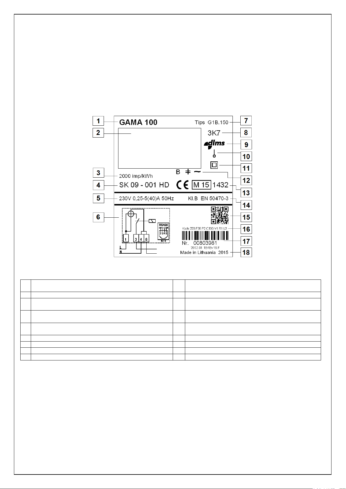
The nameplate bears all the necessary information according to EN 50470-1 and Directive
2004/22/EC, as well as identification of main data, displayed on LCD. Example of nameplate is
provided in Figure 5-3. Meter serial number is displayed as barcode (by default, barcode type
Interleaved 2/5). Additional QR (DataMatrix) code which contains the meter technical information is
printed on the nameplate.
Figure 5-3 G1B meter nameplate
Table 5-2 Explanation of Figure 5-3
1 Meter family (Gama 100) 10 The number of phases and the number of wires
(graphical symbols given in EN 62053-52)
2 Meter LCD 11 The sign of protective class II
3 The meter constant (imp/kWh) 12
4 Approval mark (number of the EC design examination
certificate)
5 Reference voltage, current measuring range, reference
frequency
6 Connection diagram or explanation of OBIS codes 15 QR code (contains the meter technical information)
7 Meter type 16 Ordering code and barcode
8 The environmental class 17 The serial number, firmware version
9 DLMS logo 18 Place and year of manufacture
Notification of LCD segments (refer to chapter
Reference source not found.)
13 The conformity marking “CE” and “M”, number of
notified body
14 The class index of the meter
5.3 Terminal block
The terminal block with all meter connections is situated behind the terminal cover. Terminal block
made from highly mechanically resistant and fire retardant insulation material and conform to the
requirements of standard DIN 43857. One utility seal in the fixing screw of the terminal cover
prevent unauthorized access to the phase connections and therefore also prevent unrecorded
energy consumption.
Current and voltage terminals can be made of zinc-plated iron or nickel-plated brass (copper) and
it provides the ability to add copper or aluminium wires without oxidation process. Terminal
assures the same quality of the contact irrespective of the shape of the connection conductor (a
compact wire, a stranded wire, greater or smaller cross-sections).
17
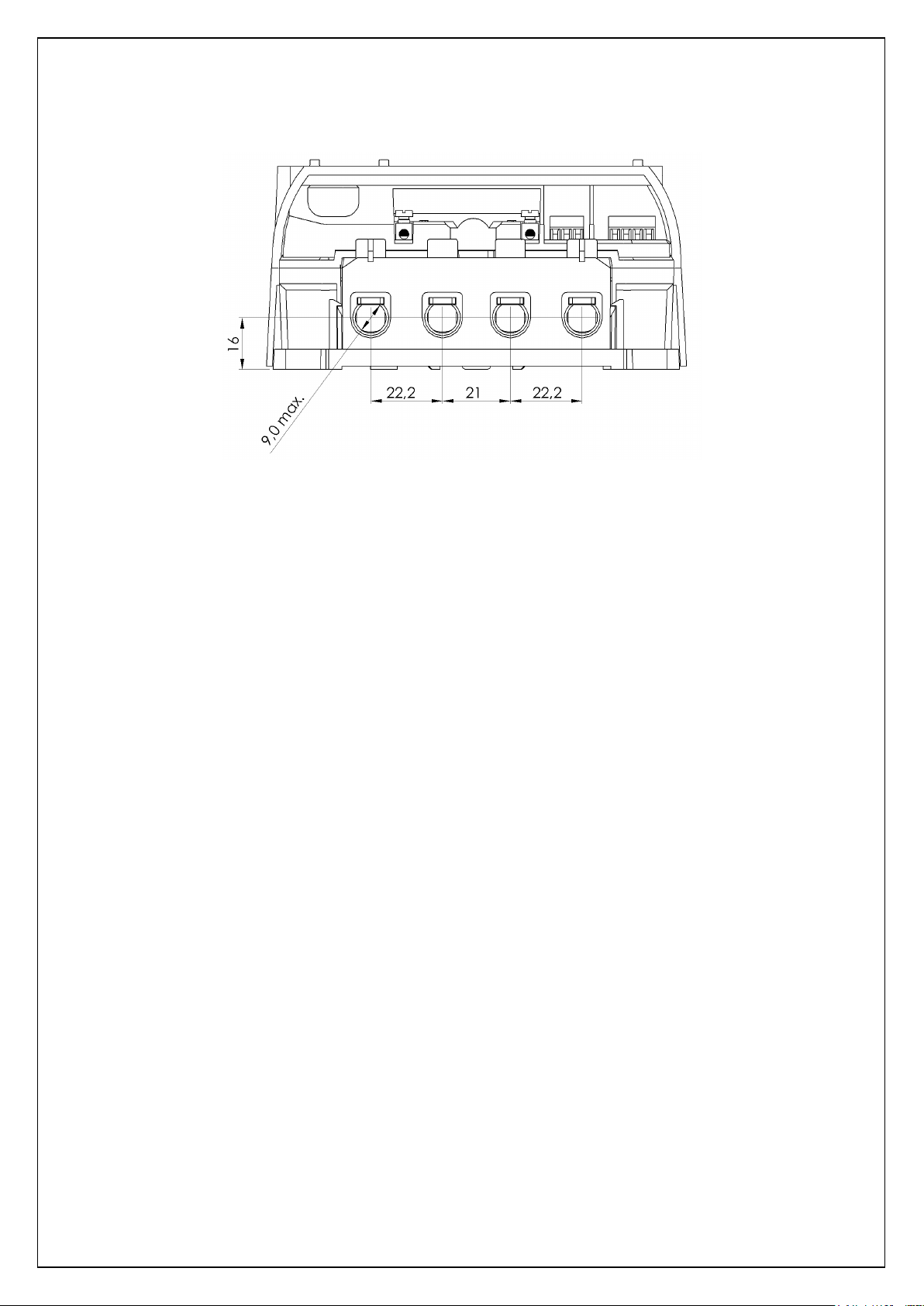
Current terminals for current up to 100 A are with 9 mm hole diameter and wires cross sectional
area at 2.5 mm2 to 60 mm2.
Figure 5-4 Meter terminal block (wires cross sectional area at 2.5 mm2 to 60 mm2)
5.4 Operation principle
5.4.1 Measurement module
In measurement module, current and voltage values of each phase are transformed into
proportionally analogous signals.
Precise current transformers, shunts or di/dt current sensors are used for current measurement in
phase circuit. In case meter contains two measurement elements (i.e. type G1B.x6x carries out
current measurement in neutral as well), current measurement in neutral circuit is based on
different type of current sensor (current transformers or shunts). For voltage measurement,
resistant voltage dividers are employed.
5.4.2 Signal conversion
Analogous signals are transformed into digital codes by three-channel Sigma - Delta converter.
Digital signal processor (DSP) calculates average power values P(t) and Q(t), as well as
instantaneous RMS values of current and voltage. Furthermore, DSP outputs values of RMS
current in neutral and electricity network frequency.
5.4.3 Micro-controller
By integrating power values, micro-controller accumulates import and export energy values.
Energy values are registered to corresponding energy and demand tariff registers in accordance
with the valid tariff program.
Furthermore micro-controller controls liquid crystal display, communication interface, meter
outputs, tariff program and internal clock.
5.4.4 Non-volatile memory
G1B meters contain non-volatile flash memory of different capacity (2048 kB). Flash memory is
used for data profiles and parameter storage. Memory retains data for 20 years and more.
5.5 Display (LCD)
Gama 100 meters are provided with a liquid crystal display (LCD). The display can be provided
with backlight for easier reading (read chapter 4.8). LCD backlight may be configured (only by
manufacturer) for one of two work modes and can work permanently or can be switched on by
18
pressing one of the buttons and is extinguished automatically after a short time if no further button
is pressed. LCD backlight can be switched on and turned off locally or remotely.
Default liquid crystal display of G1B meter contains 115 controlled segments (marked in dark
colour in Figure 5-5 - Figure 5-7). Vertical dimension of main digits is 10 mm. LCD displays
majority of data accumulated in meter and parameterization constants.
LCD divided into 7 information fields which description is not changeable and
status indication
fields (▼).
An arrow symbols
(▼)
are an additional status indication for load, billing reset block, fraud,
alarm, etc. The arrow points to a status description on the nameplate and can be allocated in
different positions for meters with default LCD (
option #1), optional LCD (option #2), and
extended LCD (option #3).
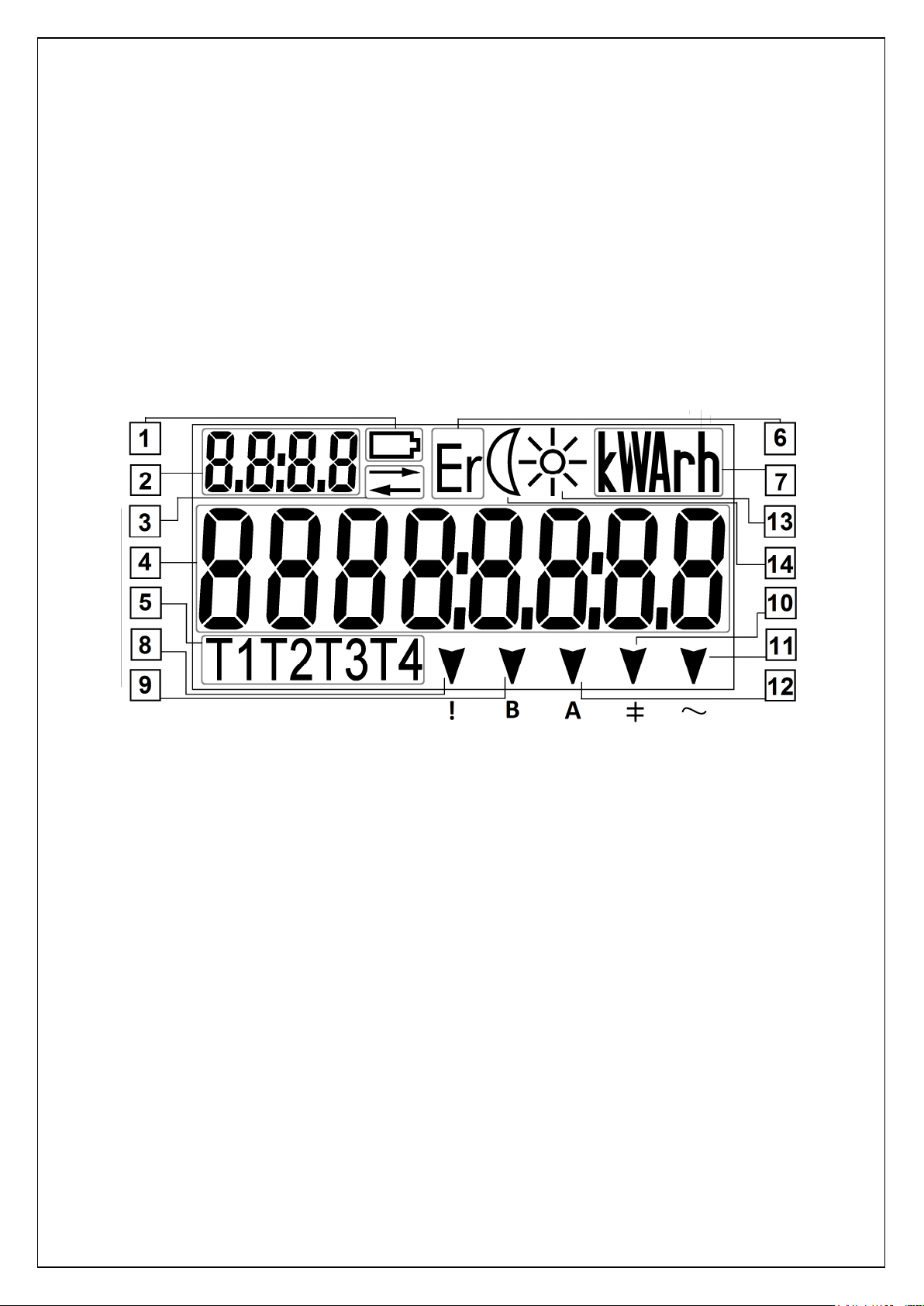
5.5.1 Default LCD (Option #1)
LCD supports indication of up to four tariffs and four symbols for OBIS code (Figure 5-5).
Figure 5-5. Segments and fields of default G1B liquid crystal display
1. Battery state indicator. The symbol appears if the voltage of battery is to low and warns
when battery has to be replaced;
2. Index field. Identifies measured data code (OBIS* code). Explanation of OBIS codes (for
basic data) can be printed on meter’s nameplate;
3. Communication indicator. Indicates when communication operates via optical or electrical
communication interface;
4. Main value field. Shows the measured value (up to 8 digit values are displayed);
5. Tariff field (T1 T2 T3 T4). Shows current energy tariff (only one segment is turned on). Lit
segment indicates active energy tariff, blinking segment indicates active emergency tariff for
energy;
6. Internal fault field (Err). Shows when internal meter error occurs;
7. Measurement unit. Shows units of measured value kW(h), kvar(h), VA, V, A, Hz;
8. Alarm (!).Warns if a contractual power limit is exceeded or neutral current imbalance
(symbol “!” is printed on the nameplate under corresponding segment);
9. Billing period reset (B). Warns about the availability to re-reset billing period. Segment is
not lit – manual billing period reset is available; segment is lit – influence by magnetic field is
registered, segment is blinking – Billing period was just reset recently and sealed pushbutton is currently blocked for some time period (symbol “B” is printed on the nameplate
under corresponding segment).
19
10. Reactive demand (╪). Segment is lit in case of reactive load (±Q). Segment is not lit in
case there is no reactive load (symbol “╪” is printed on the nameplate under corresponding
segment).
11. Active demand (~). Segment is lit in case of positive active load (+P). Segment blinks in
case of negative active load (-P). Segment is not lit in case there is no active load (symbol
“~” is printed on the nameplate under corresponding segment);
12. Fraud (A). Warns if either main cover or terminal cover was opened (symbol “A” is printed
on the nameplate under corresponding segment);
13. Reserved.
14. Reserved.
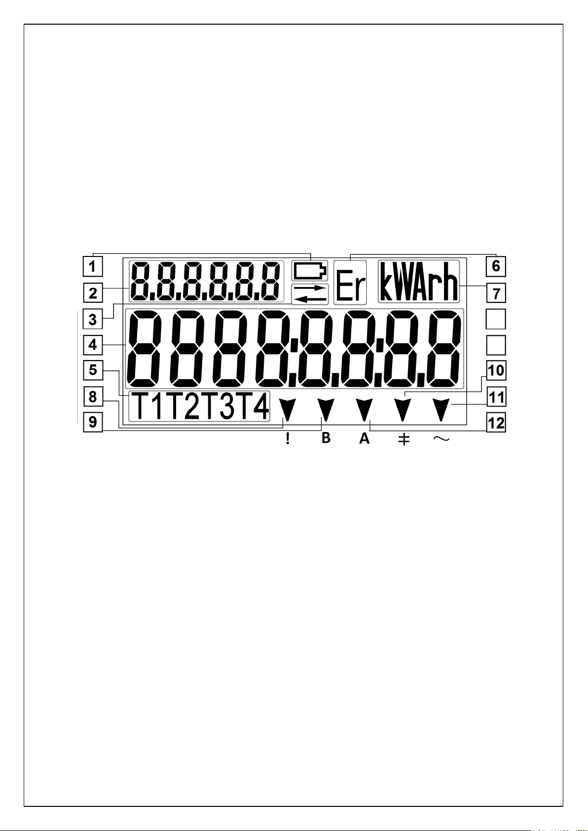
5.5.2 Optional LCD (Option #2)
LCD supports indication of up to four tariffs and six symbols for OBIS code (Figure 5-6).
Figure 5-6. Segments and fields of optional G1B liquid crystal display
1. Battery state indicator. The symbol appears if the voltage of battery is to low and warns
when battery has to be replaced;
2. Index field. Identifies measured data code (OBIS* code). Explanation of OBIS codes (for
basic data) can be printed on meter’s nameplate;
3. Communication indicator. Indicates when communication operates via optical or electrical
communication interface;
4. Main value field. Shows the measured value (up to 8 digit values are displayed);
5. Tariff field (T1 T2 T3 T4). Shows current energy tariff (only one segment is turned on). Lit
segment indicates active energy tariff, blinking segment indicates active emergency tariff for
energy;
6. Internal fault field (Err). Shows when internal meter error occurs;
7. Measurement unit. Shows units of measured value kW(h), kvar(h), VA, V, A, Hz;
8. Alarm (!).Show wen influence by magnetic field is registered (symbol “!” is printed on the
nameplate under corresponding segment);
9. Billing period reset (B). Warns about the availability to re-reset billing period. Segment is
not lit – manual billing period reset is available; segment is blinking – Billing period was just
reset recently and sealed push-button is currently blocked for some time period (symbol “B”
is printed on the nameplate under corresponding segment);
10. Reactive demand (╪). Segment is lit in case of reactive load (±Q). Segment is not lit in
case there is no reactive load (symbol “╪” is printed on the nameplate under corresponding
segment);
20
11. Active demand (~). Segment is lit in case of positive active load (+P). Segment blinks in
case of negative active load (-P). Segment is not lit in case there is no active load (symbol
“~” is printed on the nameplate under corresponding segment);
12. Fraud (A). Warns if either main cover or terminal cover was opened or a contractual power
limit is exceeded or neutral current imbalance (symbol “A” is printed on the nameplate under
corresponding segment);
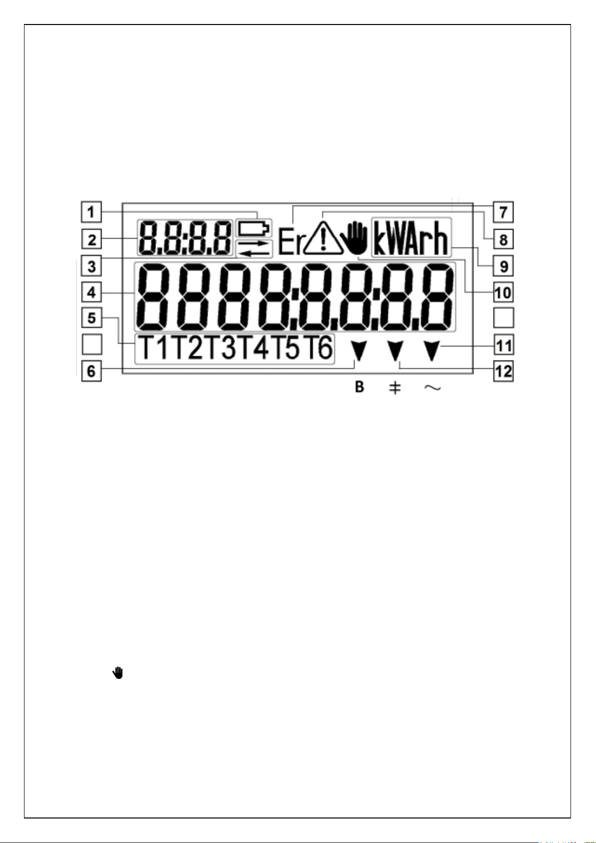
5.5.3 Extended LCD (Option #3)
LCD supports indication of up to six tariffs and four symbols for OBIS code (Figure 5-7).
Figure 5-7. Segments and fields of extended G1B liquid crystal display
1. Battery state indicator. The symbol appears if the voltage of battery is to low and warns
when battery has to be replaced;
2. Index field. Identifies measured data code (OBIS* code). Explanation of OBIS codes (for
basic data) can be printed on meter’s nameplate;
3. Communication indicator. Indicates when communication operates via optical or electrical
communication interface;
4. Main value field. Shows the measured value (up to 8 digit values are displayed);
5. Tariff field (T1 T2 T3 T4 T5 T6). Shows current energy tariff (only one segment is turned
on). Lit segment indicates active energy tariff, blinking segment indicates active emergency
tariff for energy;
6. Billing period reset (B). Warns about the availability to re-reset billing period. Segment is
not lit – manual billing period reset is available; segment is lit – influence by magnetic field is
registered, segment is blinking – Billing period was just reset recently and sealed pushbutton is currently blocked for some time period (symbol “B” is printed on the nameplate
under corresponding segment);
7. Internal fault field (Err). Shows when internal meter error occurs;
8. Alarm (!). Warns if a contractual power limit is exceeded or neutral current imbalance;
9. Measurement unit. Shows units of measured value kW(h), kvar(h), VA, V, A, Hz;
10. Fraud ( ). Warns if either main cover or terminal cover was opened;
11. Active demand (~). Segment is lit in case of positive active load (+P). Segment blinks in
case of negative active load (-P). Segment is not lit in case there is no active load (symbol
“~” is printed on the nameplate under corresponding segment);
12. Reactive demand (╪). Segment is lit in case of reactive load (±Q). Segment is not lit in
case there is no reactive load (symbol “╪” is printed on the nameplate under corresponding
segment);
21
 Loading...