

Elgama EPQS User Manual

Multifunction Meter of
active, reactive and apparent Electric Energy
EPQS
User Manual
Version 5.2a
(PQSEN52a)
“ELGAMA – ELEKTRONIKA”, Lithuania 2017


3
“ELGAMA-ELEKTRONIKA”
EPQS
Multifunction Meter of Active, Reactive and
Apparent Electric Energy
User Manual
"ELGAMA-ELEKTRONIKA" Ltd.
Visoriu str. 2,
LT-08300 Vilnius
Lithuania
Tel. 8 5 2375 000
Fax. 8 5 2375020
e-mail: info@elgama.eu

4
This user manual describes the electronic multifunction EPQS meter of electric energy and the use of
the meter. Please read this document carefully before installing and using the meter. The
manufacturer’s warranty shall not apply if the meter is damaged as a result of failure to comply with
the requirements described in this manual or registration certificate or those of work safety.
The manufacturer shall not be held liable for any kind of loss incurred by the meter parameterization
performed not following instructions described in the users program as well as recommendations and
State-defined tariffs. The manufacturer shall be not held liable for any damage related to partial or
total data loss due to unprofessional actions of authorized persons.
This user manual describes all possible features, functions, and auxiliary outputs of the electrical
energy meter. Your meter might not have some features, functions, or auxiliary outputs described in
this document. The exact configuration, features, accessories, and connection diagram of the meter is
provided in its registration certificate.

5
Table of Contents
1. PURPOSE AND FEATURES ........................................................................................................... 6
1.1. MARKING OF METER MODIFICATIONS ................................................................................................................ 7
1.2. TECHNICAL SPECIFICATIONS............................................................................................................................ 8
2. DESIGN ........................................................................................................................................... 9
2.1. CASE ............................................................................................................................................................. 9
2.2. GENERAL REQUIREMENTS AND INSTALLATION PROCEDURE ............................................................................ 10
2.3. ELECTRONIC CIRCUITRY AND PRINCIPLES OF OPERATION ................................................................................ 12
2.3.1. Measurement module ......................................................................................................................... 12
2.3.2. Analog to Digital Signal Conversion ................................................................................................... 12
2.3.3. Central Processor Unit ........................................................................................................................ 12
2.3.4. Non-volatile RAM Unit ......................................................................................................................... 13
2.3.5. Internal Clock ...................................................................................................................................... 13
2.3.6. Liquid Crystal Display (LCD) ............................................................................................................... 13
2.4. COMMUNICATION INTERFACES ....................................................................................................................... 14
2.4.1. Optical Interface (D0) .......................................................................................................................... 14
2.4.2. Electrical communication Interface ..................................................................................................... 14
2.4.3. Auxiliary Communication Interface (optional) ..................................................................................... 14
2.4.4. Interface Priorities ............................................................................................................................... 14
2.5. THE METER INPUTS AND OUTPUTS ................................................................................................................ 14
2.5.1. Optical LED Output (Red Light Emission Diodes) .............................................................................. 14
2.5.2. Pulse Output contacts ......................................................................................................................... 15
2.5.3. Relay Outputs (Optional) .................................................................................................................... 15
2.5.4. External Backup Power Supply (optional) .......................................................................................... 16
2.6. POWER SUPPLY ............................................................................................................................................ 16
2.7. PUSH BUTTON .............................................................................................................................................. 16
3. DATA REGISTRATION .................................................................................................................. 16
3.1. ENERGY REGISTRATION ................................................................................................................................ 18
3.2. DEMAND REGISTRATION ................................................................................................................................ 19
3.3. REGISTRATION OF INSTANTANEOUS VALUES .................................................................................................. 19
3.4. POWER QUALITY REGISTRATION.................................................................................................................... 21
3.5. “END OF BILLING PERIOD” .............................................................................................................................. 22
4. TARIFF MODULE .......................................................................................................................... 23
4.1. DAY PROGRAM.............................................................................................................................................. 23
4.2. WEEK PROGRAM ........................................................................................................................................... 23
4.3. TARIFF SEASONS .......................................................................................................................................... 23
4.4. SPECIAL DAYS .............................................................................................................................................. 24
4.5. TARIFF MODULE OPERATION IN CASE OF CLOCK FAILURE .............................................................................. 24
5. DATA DISPLAY MODES ............................................................................................................... 25
5.1. AUTOMATIC CYCLIC DATA INDICATION MODE ................................................................................................. 25
5.2. STATIC DATA INDICATION MODE .................................................................................................................... 25
5.3. DATA REVIEW ALGORITHMS .......................................................................................................................... 25
6. PARAMETERISATION .................................................................................................................. 27
7. METER DATA PROTECTION ........................................................................................................ 28
7.1. PHYSICAL PROTECTION OF DATA AND PARAMETERS ....................................................................................... 28
7.2. SOFTWARE PROTECTION ............................................................................................................................... 28
7.2.1. Password ............................................................................................................................................ 28
7.2.2. Lock of optical interface (optional) ...................................................................................................... 28
7.2.3. Event logbook ..................................................................................................................................... 28
7.2.4. Counters and Timers .......................................................................................................................... 29
7.2.5. Protection of Factory Constants ......................................................................................................... 29
ANNEX A. DATA AVAILABLE TO DISPLAY ON LCD........................................................................ 30

6
1. Purpose and Features
The EPQS meter is a multifunction device for measurement of electric energy. CT operated meters
comply with requirements of IEC 62053-22 standard, class 0,5 or 0,2s.
The meter data structure is compatible with DLMS standard. Each measured parameter has its OBIS
(OBject Identification System) code describing the parameter or value. OBIS codes together with
allocated parameters are transmitted through the communication interfaces and displayed on the
meter LCD display screen.
The meter measures, registers, and collects data on active energy of both directions (+A, -A), reactive
energy of both directions (+R, -R), reactive energy in four quadrants (R1, R2, R3, R4), and apparent
energy of both directions (+W, -W). The meter also registers maximums of average power, collects
load profiles and registers cumulative powers.
Besides the aforementioned values, the EPQS meter can display or transmit via its communication
interfaces the following profiles stored in any of 16 freely programmed channels: phase and line
voltages; currents; instantaneous active, reactive, and apparent power; frequency; power factor (cos
). It can also analyze power quality and generate weekly reports of power grid quality.
Up to eight of energy and the same number of power maximum tariffs can be activated for tariffication
of energy and power. The structure of tariff module lets adapt the meter for virtually any of existing
tariff program.
For remote data transmission, the meter has two independent electrical communication interfaces.
For local data readout, optical interface D0 is provided.
Several modifications of EPQS meter are manufactured. They may differ in nominal current, voltage,
connection type, and the meter hardware or software. The designation of different modifications of
EPQS meter is explained in Table 1-1.
7
1.1. Marking of meter modifications
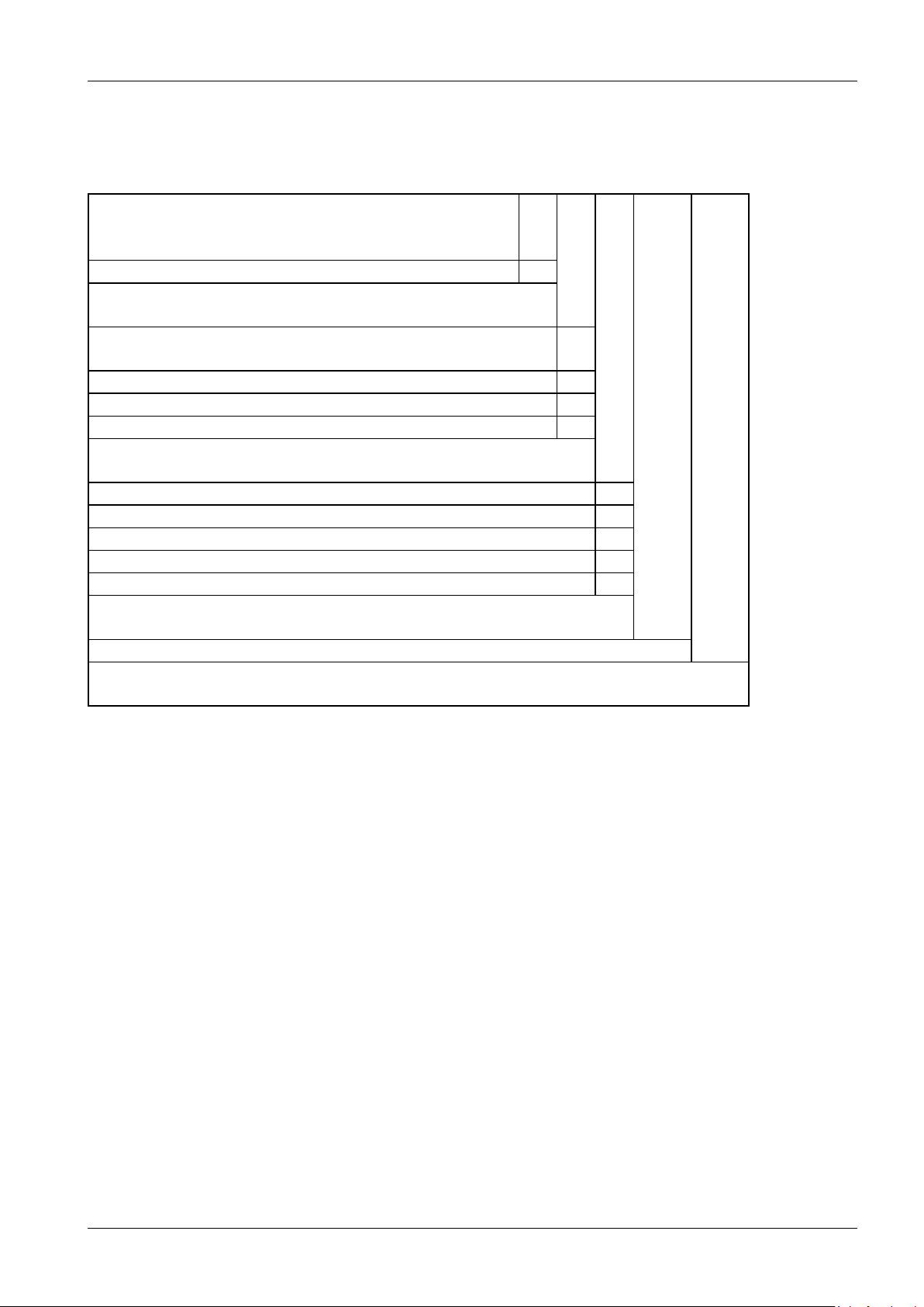
Table 1-1. Explanation of meter modification code
EPQS
X
X
X.
XX.
XX
Measuring elements:
3 elements, 4 – wire connection
1 Rated voltage, V:
3x57,7/100; 3x63,5/110; 3x69,2/120; 3x100; 3x110;
3x120
1
multi range (3x57,7 ...230/100 ...400)
2
3x220/380; 3x230/400; 3x380; 3x400
3
3x120/208; 3x127/220; 3x220; 3x230
4 Rated (maximal) current, A:
CT connection 5(6,25)
1
CT connection 5(10)
2
CT connection 1(2), 1(1,25)
3
CT connection 1(6)
4 5 Software code:
Hardware code:
Hardware of class 0.2s
2X

8
1.2. Technical Specifications
Accuracy class:
CT operated
0.2s or 0.5s (IEC 62053-22)
Rated voltage, V
see table 1-1
Rated (maximum) current, A
see table 1-1
Rated frequency, Hz
50 or 60
Sensitivity threshold, %I
nom
CT operated
0,1
Power consumption, VA
in voltage circuits
< 3 (0,76W)
in current circuits
< 0,5/phase (CT operated)
Meter constant, imp/kWh
130000
Communication interfaces:
optical interface D0
IEC 62056-21
electrical interface I
IEC 62056-31
electrical interface II
IEC 62056-31
pulse outputs:
number:
6 (independent)
output constant, imp/kWh (imp/kVArh):
130000
pulse duration, ms
30
External backup power supply:
= 12V
Tariff module:
number of energy tariffs:
programmable (1 … 8)
number of maximum demand tariffs:
programmable (1 … 8)
Data storage without power supply:
20 years (t=20°C);
2 years (t=60°С)
Backup supply of internal clock:
Li battery
Battery resource for not connected meter
> 5 years
Insulation:
pulse voltage test (IEC 60060-1)
6kV
alternating voltage test
4kV
Operating temperatures
-40°C … +60°C
Storage and transportation temperatures
-50°C … +70°C
Weight, Kg:
< 1,5
Dimensions, mm
325 x 177 x 55
9
2. Design
2.1. Case
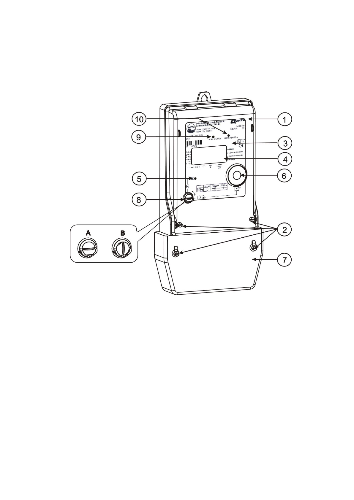
Picture 2-1 presents the external view of the device.
Picture 2-1. Meter exterior
1
Transparent cover
6
Optical communication interface;
2
Sealed screws;
7
Terminal block cover
3
Meter panel;
8
Button
4
Liquid Crystal Display;
9
Light emitting diode (LED) 1;
5
Display control photo sensor
10
Light emitting diode (LED) 2;
The meter panel is covered by transparent cover moulded from UV ray-stabilised polycarbonate cover
providing protection from external mechanical factors and moisture.
The cover is fixed to the case by two sealed screws.
The liquid crystal display (LCD) is located in the frontal part of the meter. It allows the display of all
values stored in the memory, instantaneous values and parameters.
On the lower left, a display control photo sensor is located. In order to display specific information on
the display, a corresponding light signal must be transmitted to the photo sensor.
The D0 optical interface is located on the right side of the frontal part. The purpose of this interface is
data transfer between the meter and a portable computer or terminal and the meter parameterisation.
10
The meter has its own backup power supply that provides power to the internal clock should the main
electrical network fail. The backup supply consists of a standard 3.6 V Li-Ion battery. If a –Battery lowmessage appears on the display, the battery must be replaced.
Only the manufacturer or its authorised representative may replace the battery!
The power and auxiliary terminal block is located on the bottom of the meter. All connections having
been completed and checked, the terminal block shall be covered with sealed cover.
2.2. General Requirements and Installation Procedure
1. Only personnel authorised by the Electric Utility can carry out the meter installation,
disconnection, repair, any subsequent parameterisation, and sealing; the rules of installation
of electrical devises must be observed. The manufacturer shall not be held liable for the meter
malfunction should the user fail to adhere to the relevant requirements.
2. The meter is installed in dry premises containing no chemically aggressive gases or vapour.
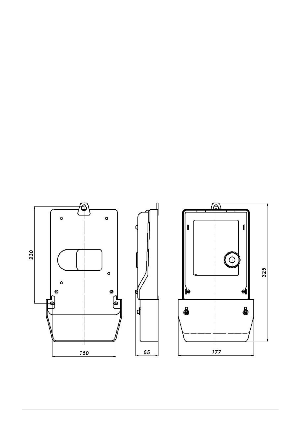
3. The meter is fixed with three screws. The meter overall dimensions and distances between the
mounting holes are shown in picture 2-2.
4. The meters are connected according to the scheme shown on the cover of the meter terminal
box diagrams. Picture 2-4 shows the general connection of EPQS meters through current and
voltage transformers.
5. Regular verification of the meter shall be carried once in eight years.
6. Only natural or legal persons authorised by the manufacturer can repair the meter.
Picture 2-2. The Overall Dimensions and Mounting Holes of EPQS Meter
11
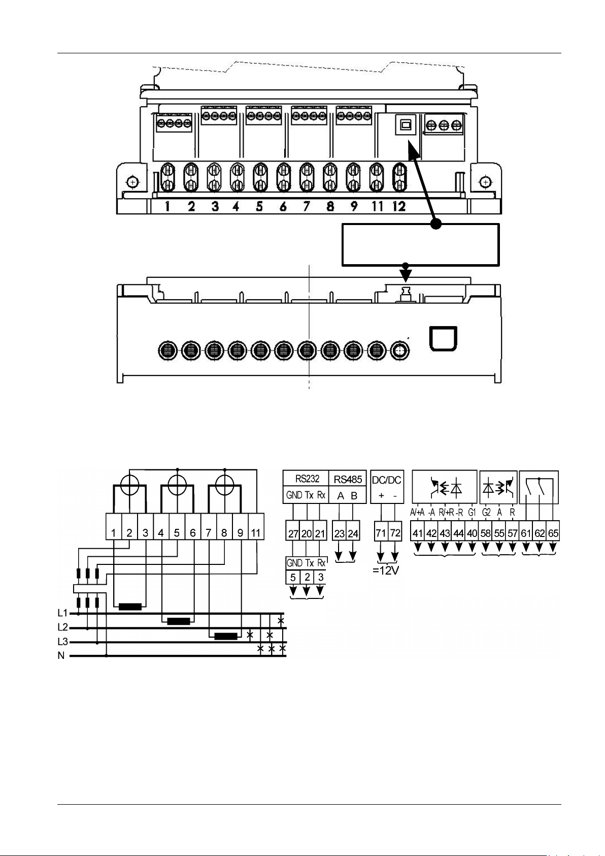
20 21 27 28 23 24 41 42 43 44 40 58 16 15 31 32 55 57 71 72 61 62 65
Terminal cover opening
button
Picture 2-3. Meter terminal box
S0 outputs Test Relay
outputs
CL1
CL2
Picture 2-4. Wiring diagram
 Loading...