

ELGA LabWater PURELAB Ultra Mk 2 Scientific, PURELAB Ultra Mk2 Bioscience, PURELAB Ultra Mk2 Genetic, PURELAB Ultra Mk2 Ionic, PURELAB Ultra Mk2 Analytic Operator's Manual

ELGA PURELAB Ultra Mk 2 Operator Manual
PURELAB Ultra Mk 2 Version 3 11/08 Page i
Copyright Note
The information contained in this document is the property of ELGA
LabWater, a division of VWS (UK) Ltd. and is supplied without liability
for errors or omissions.
No part of this document may be reproduced or used except as
authorized by contract or other written permission from VWS (UK) Ltd.
The copyright and all restrictions on reproduction and use apply to all
media in which this information may be placed.
VWS (UK) Ltd. pursue a policy of continual product improvement and
reserve the right to alter without notice the specification, design, price
or conditions of supply of any product or service.
© VWS (UK) Ltd. 2007
All rights reserved.
Publication ref: MANU38390
Version 3 11/08
ELGA
LabWater is a trading name of VWS (UK) Ltd.
ELGA® and PURELAB® are registered trademarks.

PURELAB Ultra Mk2 Operator Manual ELGA
Page ii PURELAB Ultra Mk 2 Version 3 11/08
TABLE OF CONTENTS
1. INTRODUCTION ............................................................ 1
1.1 Product Range ...................................................... 1
1.2 Use of this Manual ................................................ 1
1.3 Customer Support ................................................. 1
2. HEALTH AND SAFETY NOTES ................................... 2
2.1 Electricity ............................................................... 2
2.2 Ultraviolet Light ..................................................... 2
2.3 Sanitization Chemicals .......................................... 2
2.4 Control of Substances Hazardous to Health
(COSHH) ............................................................... 2
3. PRODUCT AND PROCESS DESCRIPTION ................ 3
3.1 Product Description ............................................... 3
3.2 Process Description .............................................. 4
3.3 Technical Specification ......................................... 9
4. CONTROLS ................................................................. 12
5. INSTALLATION INSTRUCTIONS ............................... 13
5.1 Unpacking the PURELAB Ultra ......................... 13
5.2 Positioning the PURELAB Ultra ......................... 13
5.3 Connecting the PURELAB Ultra ........................ 15
5.4 Initial Controller Set up ........................................ 17
5.5 Setting Up Password / Resetting Replacement
Timers ................................................................. 22
5.6 Initial Start Up ..................................................... 24
5.7 POU Filter Installation (LC134) - Optional
Accessory ........................................................... 26
6. OPERATION ................................................................ 27
6.1 Intermittent or Continuous Recirculation ............. 27
6.2 Manual Dispense ................................................ 28
6.3 Profile Dispense .................................................. 28
6.4 Dispense Porfiling ............................................... 28
6.5 Automatic Calibration .......................................... 29
6.6 Water Supply Flush ............................................. 30
7. MAINTENANCE ........................................................... 31
7.1 Replacing the Purification Packs ........................ 31
7.2 Replacing the Ultra-Microfilter (LC109) ............... 33
7.3 Replacing the Ultrafilter (LC151) ......................... 35
7.4 Replacing the Ultraviolet Lamp (LC105 and
LC118) ................................................................ 37
7.5 Replacing the Point-Of-Use Filter (LC134) ......... 38
7.6 Cleaning the Inlet Strainer (External) .................. 39

ELGA PURELAB Ultra Mk 2 Operator Manual
PURELAB Ultra Mk 2 Version 3 11/08 Page iii
8. SANITIZATION PROCEDURES .................................. 40
8.1 CT1 Sanitization Tablet - Safety Information ....... 42
9. TROUBLE SHOOTING ................................................ 43
10. CONSUMABLES AND ACCESSORIES ..................... 44
11. KEY TO CONTROL PANEL ........................................ 45
11.1 Icons .................................................................... 45
11.2 Alarm Conditions ................................................. 46
11.3 Replacement Timers ........................................... 46
11.4 Quality Alarms ..................................................... 47
12. WARRANTY/CONDITIONS OF SALE ........................ 48
13. USEFUL CONTACT DETAILS .................................... 50

ELGA PURELAB Ultra Mk 2 Operator Manual
PURELAB Ultra Mk2 Version 3 11/08 Page 1
1. INTRODUCTION
1.1 Product Range
This operator manual has been prepared for the PURELAB Ultra
product models:
PURELAB Ultra Mk 2 Scientific
PURELAB Ultra Mk2 Bioscience
PURELAB Ultra Mk2 Genetic
PURELAB Ultra Mk2 Ionic
PURELAB Ultra Mk2 Analytic
1.2 Use of this Manual
This manual contains full details on installation, commissioning and
operation of the PURELAB Ultra unit. If the instructions in this
handbook are not followed then the performance of this product
and/or the safety of the user may be compromised.
1.3 Customer Support
Service support and consumable items are available from your local
supplier or distributor. Refer to customer service contact details shown
at the end of this publication.
PURELAB Ultra
PURELAB Ultra Mk2 Operator Manual ELGA
Page 2 PURELAB Ultra Mk 2 Version 3 11/08
2. HEALTH AND SAFETY NOTES
PURELAB Ultra products have been designed to be safe, however, it
is important that personnel working on these units understand any
potential dangers. All safety information detailed in this handbook is
highlighted as WARNING and CAUTION instructions. These are used
as follows:
WARNING! WARNINGS ARE GIVEN WHERE FAILING
TO OBSERVE THE INSTRUCTION COULD
RESULT IN INJURY OR DEATH TO
PERSONS.
CAUTION! Cautions are given where failure to
observe the instruction could result in
damage to the equipment, associated
equipment and processes.
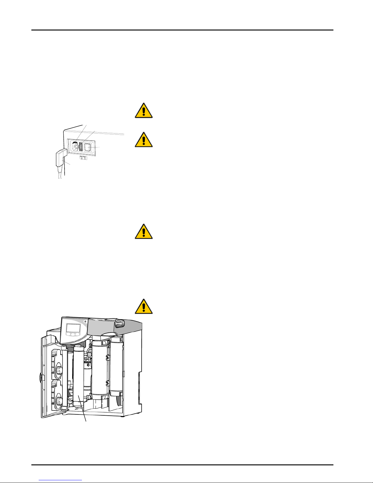
2.1 Electricity
It is essential that the electrical supply to the PURELAB Ultra is
isolated before any items are changed or maintenance work
performed.
The ON/OFF switch is located at the left-hand side of the unit. The
mains power lead is located just behind the ON /OFF switch.
WARNING! THIS APPLIANCE MUST BE EARTHED.
The main water supply should be isolated and residual pressure
released prior to removal of any Purification Packs or carrying out
work on the unit.
Switching off the electrical supply will isolate the source of mains
water pressure.
2.2 Ultraviolet Light
WARNING! UNDER NO CIRCUMSTANCES SHOULD
THE LAMP BE CONNECTED AND
ACTIVATED WHEN OUTSIDE THE
HOUSING.
The Genetic, Analytic and Ionic units are fitted with an ultraviolet lamp.
The UV lamp is enclosed in a stainless steel chamber ensuring that
the operator will not be exposed to UV light.
2.3 Sanitization Chemicals
During the sanitization cycle a CT1 sanitization tablet is used and
relevant safety information is included in this handbook. A safety data
sheet conforming to COSHH regulations is also provided with the
tablets and should be read before a tablet is used.
2.4 Control of Substances Hazardous to Health (COSHH)
Material safety data sheets covering the various replaceable
Purification Packs are available upon request. Contact your local
supplier or distributor.
Fuse
ON/OFF
switch
Mains power lead
Mains power socket
Mains Power Supply
UV Lamp
Ultra with UV Lamp
ELGA PURELAB Ultra Mk 2 Operator Manual
PURELAB Ultra Mk2 Version 3 11/08 Page 3
3. PRODUCT AND PROCESS
DESCRIPTION
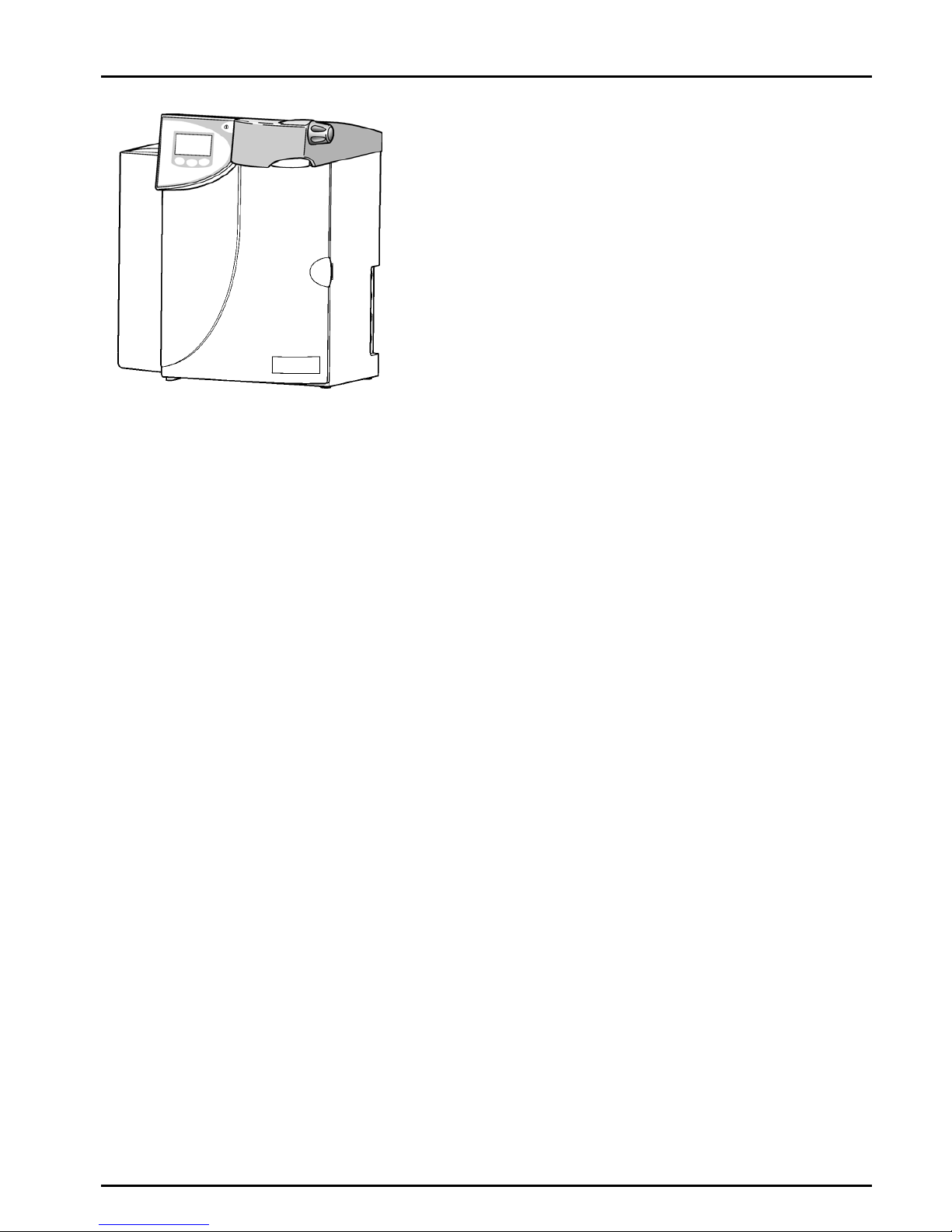
3.1 Product Description
The PURELAB Ultra water purification unit has been specifically
designed to provide a supply of ultrapure water with very low levels
of impurities for laboratory, medical and industrial applications.
The PURELAB Ultra can be bench, under bench or wall mounted
with an optional wall mounting kit. A range of accessories is available
to complement the unit (see Section 10 - Consumables and
Accessories, for details).
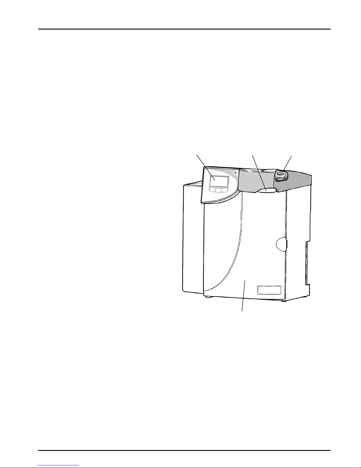
Control Panel Dispense Nozzle Dispense Controller
Door
PURELAB Ultra
The PURELAB Ultra range of water purification units has been
designed to provide the ultimate in high purity water for laboratory
applications. The products need to be fed with pre-treated water,
typically from a reverse osmosis supply. They can be operated directly
from a ringmain feed as point of use polishers, with or without local
buffer storage, using a Docking Vessel or suitable reservoir.
Alternatively, they can be supplied from a local pre-treatment/storage
system, for example a PURELAB Prima and Docking Vessel
combination.
PURELAB Ultra Mk2 Operator Manual ELGA
Page 4 PURELAB Ultra Mk 2 Version 3 11/08
3.2 Process Description
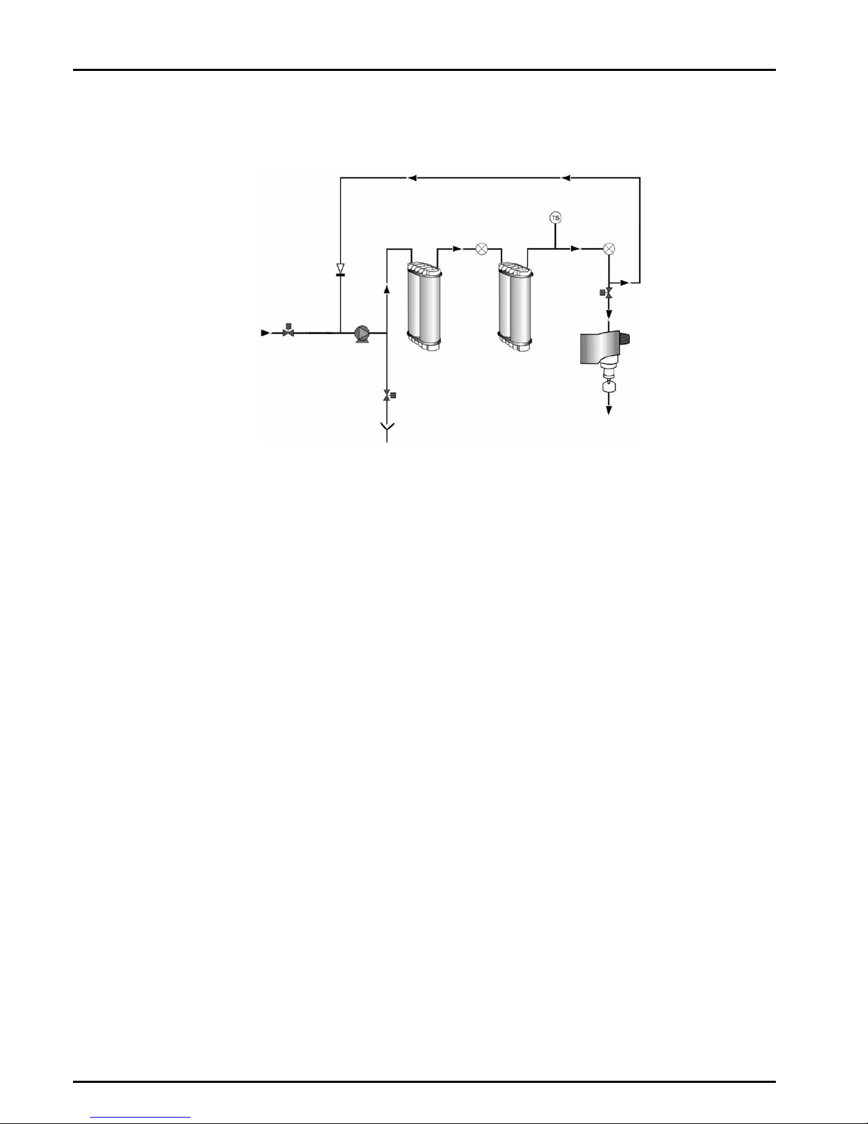
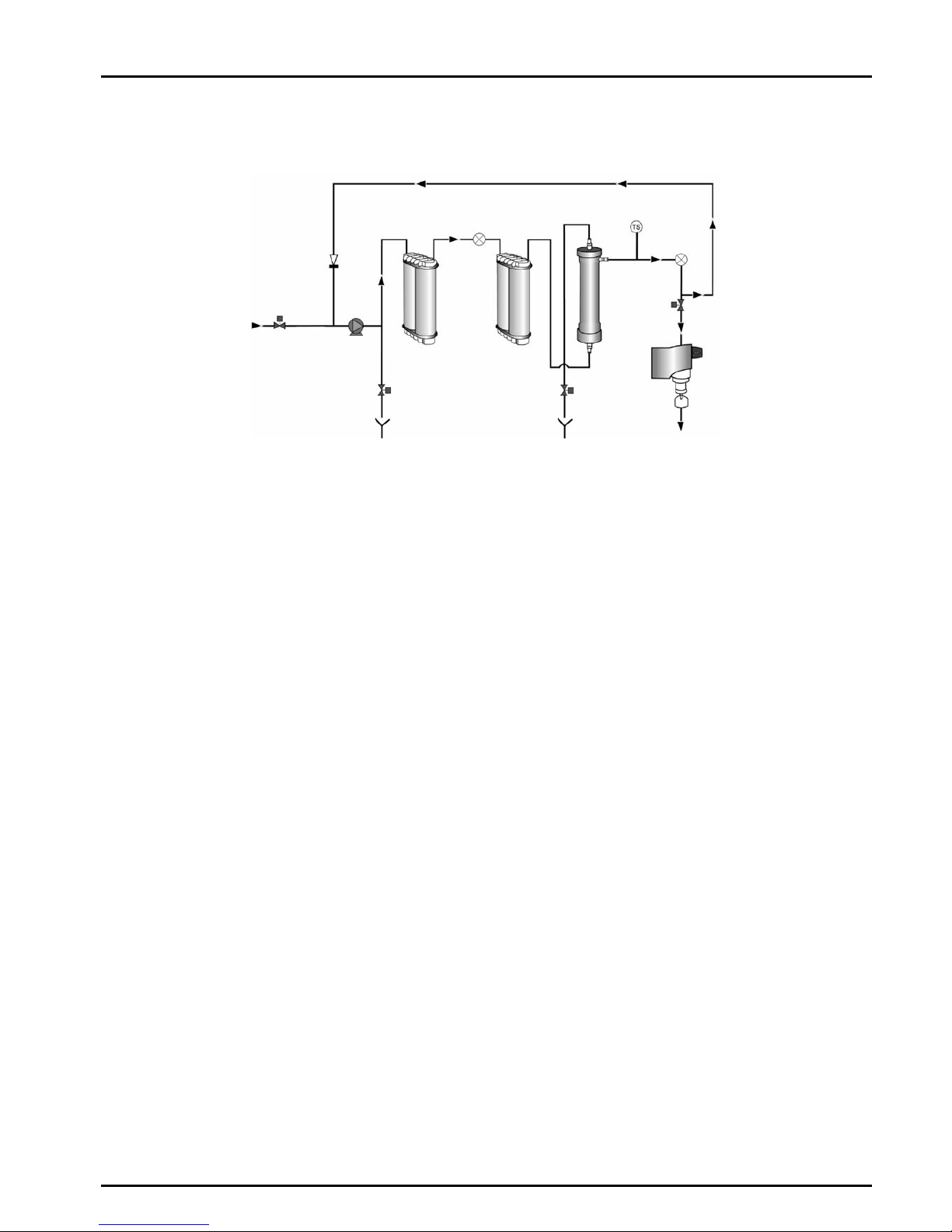
Scientific
Pre-treated water enters via an inlet solenoid, and is pumped
through the primary purification pack, an intermediate water
quality sensor, a polishing purification pack and final
temperature and water quality sensors before being
dispensed or re-circulated through a non-return valve back to
the pump inlet.
The first purification pack removes most of the impurities
from the water. The intermediate water quality sensor
measures the resistivity of the water from the first pack and
initiates an alarm when the pack needs to be replaced.
Any remaining ionic and organic impurities are removed by
the second polishing purification pack. Product water
resistivity and temperature are measured before dispense.
The water within the unit is re-circulated through the
purification technologies to maintain purity. To minimize heat
build up the recirculation is at reduced flow rate and can be
set to be intermittent (10 minutes every hour). Similarly,
intermittent recirculation can be used overnight in 'sleep
mode'.
An optional POU filter is available if required to protect the
outlet from bacterial contamination.
Solenoid
Valve
NRV
Feedwater Inlet
(Pre-purified Water)
Pump
Solenoid Valve
Drain
Purified Water
Outlet
Primary
Purification
Pack
Polishing
Purification
Pack
0.2µm Point-of-use Filter
(Optional)
Dispense Controller
Outlet Water
Quality Sensor
Temperature
Sensor
Intermediate
Water Quality
Sensor
Solenoid Valve
ELGA PURELAB Ultra Mk 2 Operator Manual
PURELAB Ultra Mk2 Version 3 11/08 Page 5
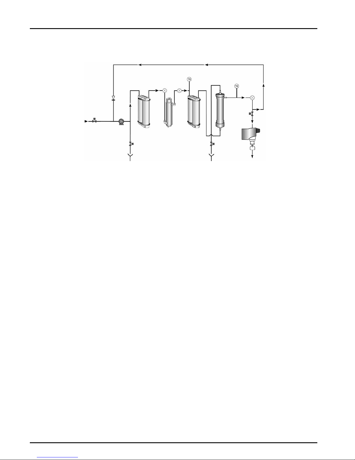
Bioscience
Pre-treated water enters via an inlet solenoid and is pumped
through the primary purification pack, an intermediate water
quality sensor, a polishing purification pack, an ultrafilter and
final temperature and water quality sensors before being
dispensed or re-circulated through a non-return valve back to
the pump inlet.
The first purification pack removes most of the impurities
from the water. The intermediate water quality sensor
measures the resistivity of the water from the first pack and
initiates an alarm when the pack needs to be replaced.
Any remaining ionic and organic impurities are removed by
the second polishing purification pack; the ultrafilter removes
pyrogens, bacteria and other microbial impurities as well as
particles. Product water resistivity and temperature are
measured before dispense.
The water within the unit is re-circulated through the
purification technologies to maintain purity. To minimize heat
build up the recirculation is at reduced flow rate and can be
set to be intermittent (10 minutes every hour). Similarly,
intermittent recirculation can be used overnight in 'sleep
mode'.
An optional POU filter is available if required to protect the
outlet from bacterial contamination.
0.2µm Point-of-use Filter
(Optional)
Purified Water
Outlet
Solenoid Valve
Feedwater Inlet
(Pre-purified Water)
Intermediate
Water
Quality Sensor
Temperature
Sensor
Outlet Water
Quality Sensor
Solenoid Valve
Drain
Drain
Primary
Purification
Pac
k
Polishing
Purification
Pack
Pump
NRV
Dispense Controller
Flush
Solenoid
Valve
Ultrafiltration
Membrane
Solenoid
Valve
PURELAB Ultra Mk2 Operator Manual ELGA
Page 6 PURELAB Ultra Mk 2 Version 3 11/08
Genetic
Pre-treated water enters via an inlet solenoid, and is pumped
through the primary purification pack and an intermediate
water quality sensor. The water then flows through a UV
chamber, further resistivity and temperature sensors, a
polishing purification pack, an ultrafilter and final temperature
and water quality sensors before being dispensed or recirculated through a non-return valve back to the pump inlet.
The first purification pack removes most of the impurities
from the water. The intermediate water quality sensor
measures the resistivity of the water from the first pack and
initiates an alarm when the pack needs to be replaced.
Purified water flows directly through the UV chamber where it
is exposed to intense UV radiation at wavelengths of 254nm
and 185nm to provide continuous bacterial control and the
photo-oxidation of residual organic impurities. The second
temperature compensated water quality sensor provides data
for TOC monitoring.
Any remaining ionic and organic impurities are removed by
the second polishing purification pack; the ultrafilter removes
pyrogens, bacteria and other microbial impurities as well as
particles. Final water resistivity and temperature are
measured before dispense.
The water within the unit is re-circulated through the
purification technologies to maintain purity. To reduce heat
build up the recirculation is at reduced flow rate and can be
set to be intermittent (10 minutes every hour). Similarly,
intermittent recirculation can be used overnight in 'sleep
mode'.
An optional POU filter is available if required to protect the
outlet from bacterial contamination.
Solenoid Valve
Outlet Water
Quality Sensor
Intermediate
Water
Quality
Sensor
Primary
Purification
Pack
Polishing
Purification
Pack
Dispense Controller
Drain
Solenoid
Valve
Pump
NRV
Temperature
Sensor
UV Lamp
Drain
Feedwater Inlet
(Pre-purified Water)
Solenoid Valve
0.2µm Point-of-use Filter
(Optional)
Purified Water
Outlet
Ultrafiltration
Membrane
Post UV
Quality
Sensor
Temperature
Sensor
Flush
Solenoid
Valve

ELGA PURELAB Ultra Mk 2 Operator Manual
PURELAB Ultra Mk2 Version 3 11/08 Page 7
Ionic
Pre-treated water enters via an inlet solenoid and is pumped
through the primary purification pack and an intermediate
water quality sensor. The water then flows through a UV
chamber, a further resistivity and temperature sensor, a
polishing purification pack, an ultra microfilter and final
temperature and water quality sensors before being
dispensed or re-circulated through a non-return valve back to
the pump inlet.
The first purification pack removes most of the impurities
from the water. The intermediate water quality sensor
measures the resistivity of the water from the first pack and
initiates an alarm when the pack needs to be replaced.
Purified water flows directly through the UV chamber where it
is exposed to intense UV radiation at a wavelength of 254nm
to provide continuous bacterial control.
Any remaining ionic and organic impurities are removed by
the second polishing purification pack; the ultra microfilter
removes bacterial impurities and particles. Product water
resistivity and temperature are measured before dispense.
The water within the unit is re-circulated through the
purification technologies to maintain purity. To reduce heat
build up the recirculation is at reduced flow rate and can be
set to be intermittent (10 minutes every hour). Similarly,
intermittent recirculation can be used overnight in 'sleep
mode'.
An optional POU filter is available if required to protect the
outlet from bacterial contamination.
Feedwater Inlet
(Pre-purified Water)
Solenoid
Valve
Pump
NRV
Solenoid Valve
Drain
Primary
Purification
Pack
Polishing
Purification
Pack
UV Lamp
UMF
Intermediate
Water Quality
Sensor
Outlet Water
Quality
Sensor
Temperature
Sensor
Solenoid Valve
Dispense Controller
0.2µm Point-of-use Filter
(Optional)
Purified Water
Outlet

PURELAB Ultra Mk2 Operator Manual ELGA
Page 8 PURELAB Ultra Mk 2 Version 3 11/08
Analytic
Pre-treated water enters via an inlet solenoid and is pumped
through the primary purification pack and an intermediate
water quality sensor. The water then flows through a UV
chamber, further resistivity and temperature sensors, a
polishing purification pack, an ultra microfilter and final
temperature and water quality sensors before being
dispensed or re-circulated through a non-return valve back to
the pump inlet.
The first purification pack removes most of the impurities
from the water. The intermediate water quality sensor
measures the resistivity of the water from the first pack and
initiates analarm when the pack needs to be replaced.
Purified water flows directly through the UV chamber where it
is exposed to intense UV radiation at wavelengths of 254nm
and 185nm to provide continuous bacterial control and the
photo-oxidation of residual organic impurities. The second
temperature compensated water quality sensor provides data
for TOC monitoring.
Any remaining ionic and organic impurities are removed by
the second polishing purification pack; the ultra microfilter
removes bacterial impurities and particles. Product water
resistivity and temperature are measured before dispense.
The water within the unit is re-circulated through the
purification technologies to maintain purity. To reduce heat
build up the recirculation is at reduced flow rate and can be
set to be intermittent (10 minutes every hour). Similarly,
intermittent recirculation can be used overnight in 'sleep
mode'.
An optional POU filter is available if required to protect the
outlet from bacterial contamination.
Feedwater Inlet
(Pre-purified Water)
Solenoid
Valve
Solenoid Valve
Pump
Primary
Purification
Pack
UV Lamp
Polishing
Purification
Pack
UMF
0.2µm Point-of-use Filter
(Optional)
Purified Water
Outlet
Solenoid Valve
Intermediate
Water
Quality
Sensor
Temperature
Sensor
Outlet Water
Quality
Sensor
Drain
NRV
Dispense Controller
Post UV
Quality
Sensor
Temperature
Sensor

ELGA PURELAB Ultra Mk 2 Operator Manual
PURELAB Ultra Mk2 Version 3 11/08 Page 9
3.3 Technical Specification
The Technical Specifications for the PURELAB Ultra are as follows:
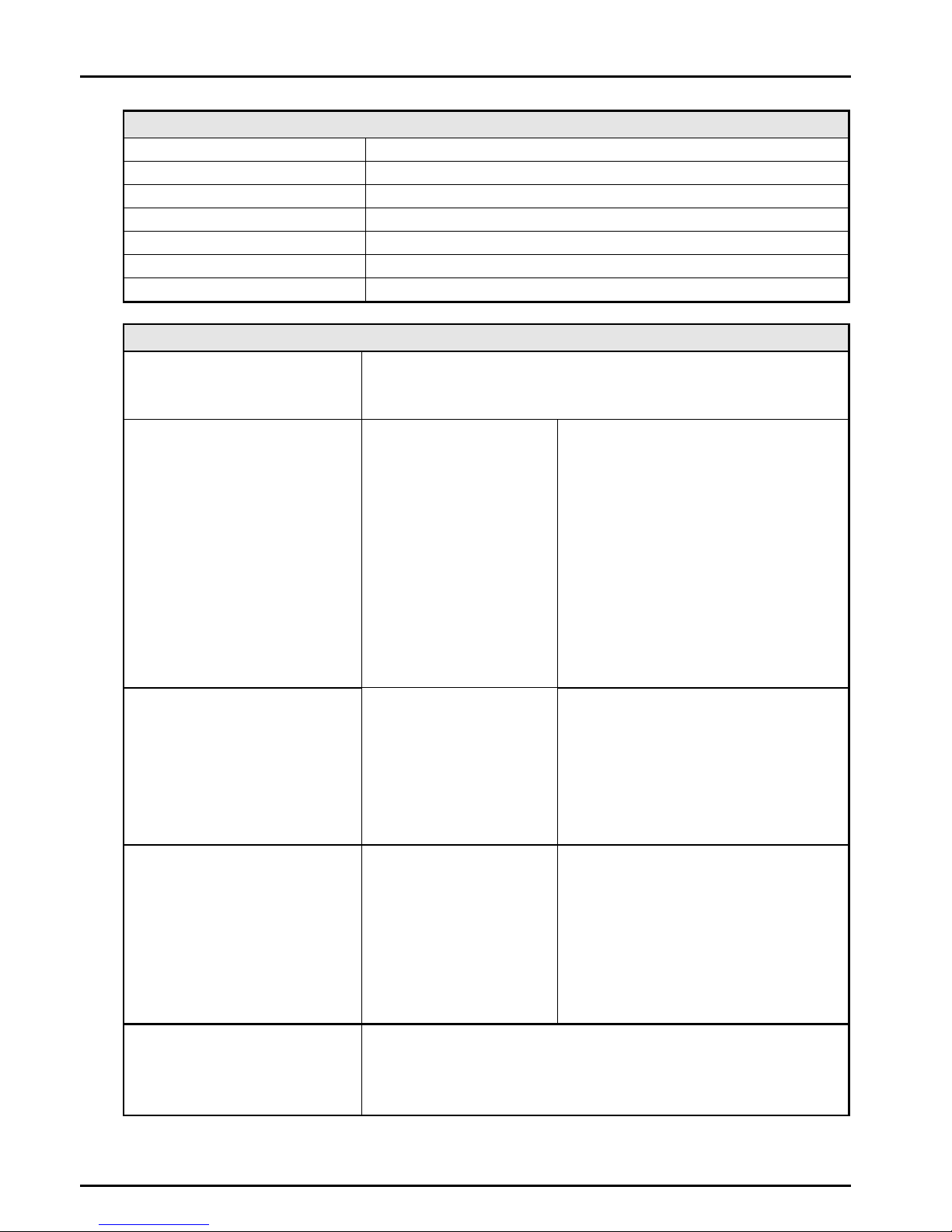
Feedwater*
Parameter Limits
Source - Originally from potable supply,
then pre-treated
Preferably reverse osmosis (RO) or filtered service deionisation (SDI) or distilled.
Note: mixed bed or twin bed deionised supplies should be cation limited at exhaustion.
Fouling Index (max) 1 for all models. A 0.2 micron membrane prefilter is recommended for all non-RO feeds
Service Deionisation (SDI) - MΩ-cm 1 MΩ-cm minimum resistivity at exhaustion
Reverse Osmosis (RO) - µS/cm Recommended < 30 µS/cm
Free Chlorine 0.05 ppm max.
TOC Recommended 50 ppb max.
Carbon Dioxide 30 ppm max.
Silica 2 ppm max.
Particulates Filtration down to 0.2 micron advisable to protect internal and/or point of use filters
Temperature 1-40°C - Recommended 10-15°C
Flowrate (maximum requirement) 130 l/hr
Drain requirements (gravity fall with air gap).
Maximum during service
Up to 2 l/min
Feedwater Pressure 0.7 bar (10 psi), maximum, 0.07 bar (1 psi) minimum
* Contact technical support for advice on feedwaters outside the range listed.
Note: Different system configurations are available for different feedwater sources. See system set up.
Dimensions
Height 490mm (19.3")
Width 410mm (16.2")
Depth 365mm (14.4")
Weight
Scientific 14.0kg (30.8 lb)
Bioscience 14.5kg (32.0 lb)
Ionic 14.5kg (32.0 lb)
Analytic 15.0kg (33.1 lb)
Genetic 15.0kg (33.1 lb)
Connections
Inlet-quick connect 8mm (5/16") OD
Drain 8mm (5/16") OD
Flush - Bioscience/ Genetic 8mm (5/16") OD
Positioning Wall, bench or under bench mounted
Environment Clean dry indoor. Temp 5-40°C
Humidity max 80% non-condensing
PURELAB Ultra Mk2 Operator Manual ELGA
Page 10 PURELAB Ultra Mk 2 Version 3 11/08
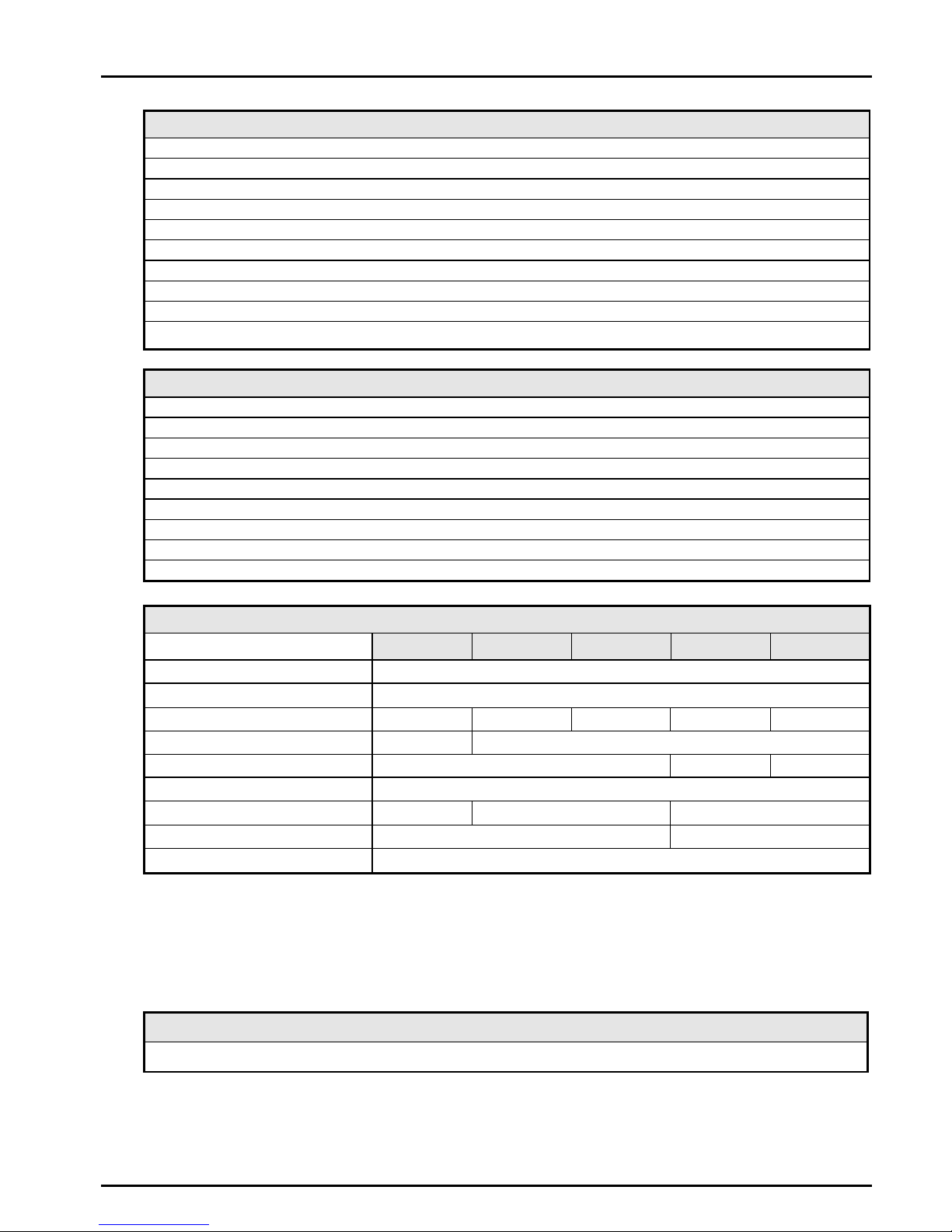
Electrical Requirements
Mains input 100 -240V ac, 50-60Hz all models
System voltage 24V dc
Power consumption during recirculation 60VA
Power consumption during dispense 75VA
Fuses 2 x T6.3 Amp
Reservoir level connection Jack Plug 3.5mm
Noise level during recirculation <40dBA
User Interface
Display Continuous graphical quality display
Graphical flow schematic on screen with mimic display
Backlit display with Intuitive Icons
Adjustable settings Timed dispense Selectable dispense times (10 secs - 60 min)
Profile dispense Selectable dispense volumes
Recirculation mode Intermittent or continuous
Feed water type Selectable (RO/DI/SDI)
Display viewing angle Adjustable electronically
Water quality units
Selectable (MΩ-cm or µS/cm)
Water quality alarm Selectable alarm setpoints
Date / time Adjustable
Auto restart after power failure Selectable (On/Off)
Audible alarm Selectable (On/Off)
Temperature control Selectable alarm setpoints
Night service Selectable (On/Off)
Indicators Product water quality Resistivity or conductivity
Intermediate water quality Resistivity or conductivity
Temperature Degrees Centigrade or Fahrenheit
Total Organic Carbon (TOC)* Concentration ppb C (µg/l C)
Purification pack Replacement date
UV lamp* Replacement date
Filter* Replacement date
Alarms-Audiovisual Purified water purity Above set point alarm
Temperature**** Above set point alarm
UV lamp operation* Imminent lamp failure or failure to start
Calibration Calibration alarm – calibration required
Purification pack Change reminder
UV lamp* Change reminder
Filter* Change reminder
Reservoir**** Low level / level control disconnect alarm
Outputs RS232 printer connection
RS232 remote display connection
Volt free contact-internal
Remote dispense
ELGA PURELAB Ultra Mk 2 Operator Manual
PURELAB Ultra Mk2 Version 3 11/08 Page 11
Safety Features
Power fail safe
Water temperature alarm
Water quality alarm
Purification pack interlock
UV current monitoring
Timeout of manual dispense
Low operating voltage 24V
Dry contact alarm connection
Visual alarms
Audible alarms
Operational Features
Low noise levels – minimum intrusion
Continuous calibration to traceable standards
Drop dispense
Multistage monitoring
Restart on power interrupt
Profile dispense
Timed dispence
Optional printer kit to record operating parameters
Optional remote display
Purified Water Specification
Scientific Ionic Analytic Bioscience Genetic
Flowrate 2.0 l/min max.
Inorganic
Resistivity 18.2 MΩ-cm (0.055µS/cm)
TOC 3-10 ppb** 3-10 ppb** 1-2 ppb** 3-10 ppb** 3-10 ppb**
Bacteria <1 cfu/ml*** <1 cfu/10 ml, *** <1 cfu/ml (without POU fitted)
Bacterial Endotoxins <0.001 Eu/ml <0.001 Eu/ml
pH Effectively neutral
Particles
0.2 µm*** 0.05 µm
Ultrafiltration
RNase / DNase - Removed
Capacity (LC182)
Liters at 18.2 MΩ-cm = 80,000 / (µS/cm at 2.3 x ppm CO
2
)
* On some models only.
** Dependant on feedwater - recommended feed < 50 ppb TOC.
*** With POU filter fitted.
**** Switches process off.
Purification Packs
Labpure S1 LC182 recommended for most applications. Refer to Section 10 for alternative cartridges.
As part of our policy of continual improvement we reserve the right to
alter the specifications given in this document.
PURELAB Ultra Mk2 Operator Manual ELGA
Page 12 PURELAB Ultra Mk 2 Version 3 11/08
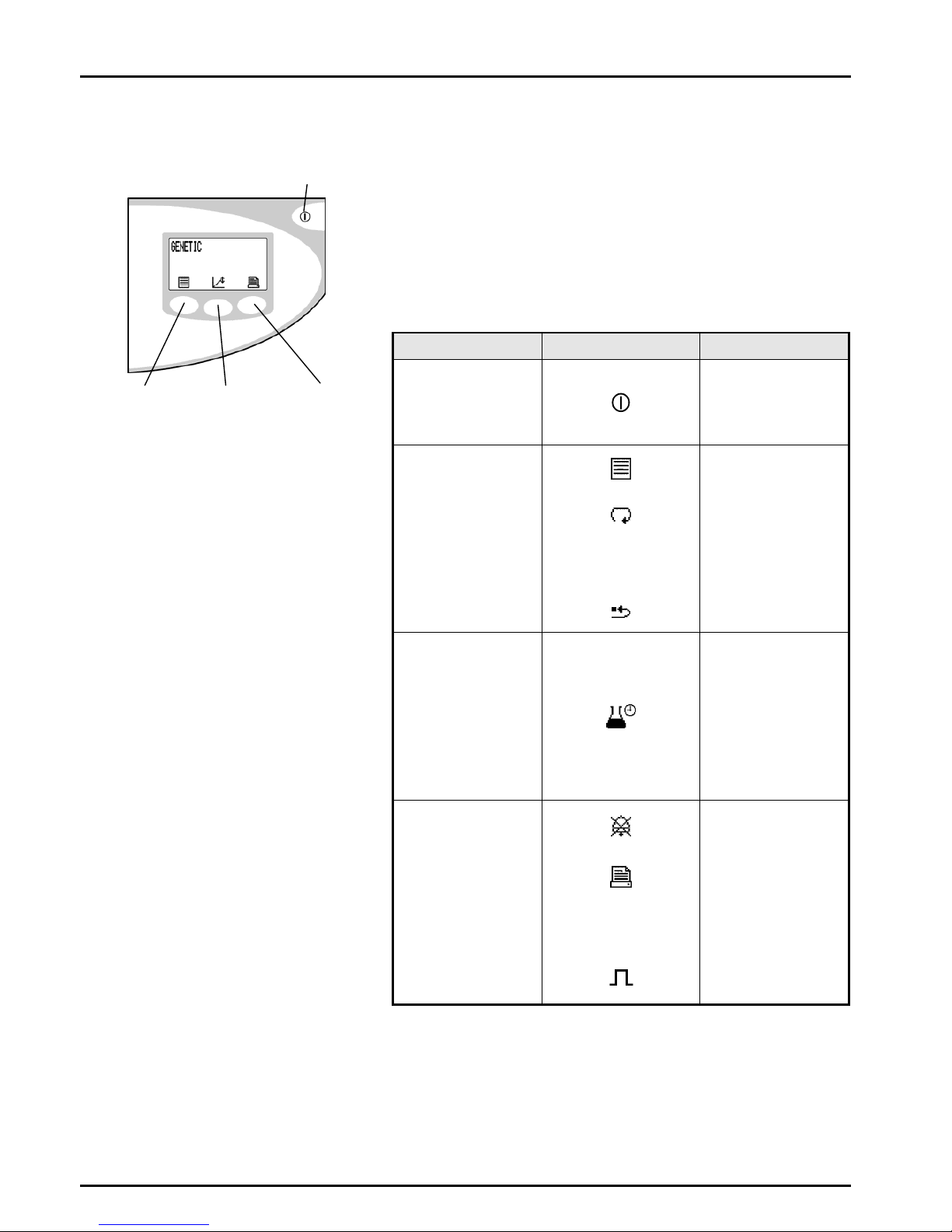
4. CONTROLS
The PURELAB Ultra operates with a tactile membrane control panel,
which has a graphics display window and four multi-purpose control
buttons.
Details of how to use the controls will be given in the appropriate
sections.
The PURELAB Ultra control panel has a range of control icons as
follows:
Button Icon Function
PROCESS
Turns the process
on/off
ESCAPE from any
feature
LEFT
Menu
Scroll
M1
Profile dispense
memory
Reset
CENTRE
9
Accept
Profile/Timed
dispense
M2
Profile dispense
memory
RIGHT
Mute Alarm
Printer
M3
Profile dispense
memory
Intermittent
recirculation
Process button
Left hand Centre Right hand
Control button Control button Control button
Control Panel
ELGA PURELAB Ultra Mk 2 Operator Manual
PURELAB Ultra Mk2 Version 3 11/08 Page 13
5. INSTALLATION INSTRUCTIONS
5.1 Unpacking the PURELAB Ultra
The following items are supplied with your PURELAB Ultra:
1. PURELAB Ultra unit.
2. Sanitization by-pass blocks LA638 (2 off, fitted in unit).
3. 6 metres of 8mm (5/16") O/D tube.
4. 1 off Pack of CT1 tablets.
5. 1 off Strainer Assembly.
6. Operator Manual in English.
7. Multilingual Operator Manual on CD.
8. Mains Lead.
9. Reservoir Level Connecting Lead.
5.2 Positioning the PURELAB Ultra
Before installation and operation of the PURELAB Ultra unit, please
read and observe the following points:
Environment
The unit should be installed on a flat, level surface, in a
clean, dry environment. The unit can also be wall mounted
against a vertical wall capable of supporting the weight (for
this we recommend the use of the wall mounting kit Part No.
LA610 on substantial brick/concrete walls or LA622 for stud
partition walls).
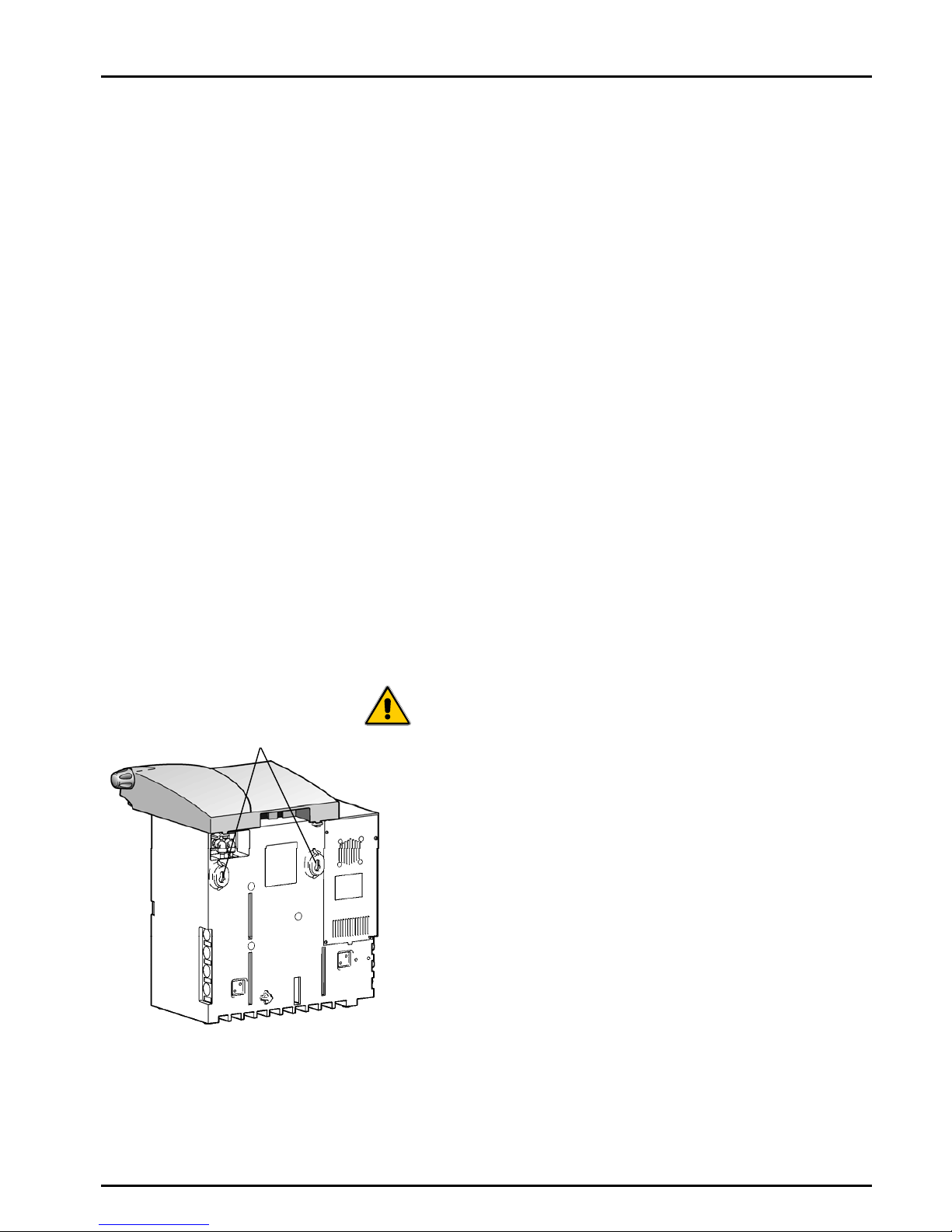
WARNING! IF THE UNIT IS TO BE WALL MOUNTED,
ENSURE IT IS MOUNTED USING THE
CORRECT WALL MOUNTING KIT AND
THAT THE WALL IS CAPABLE OF
SUPPORTING THE OPERATING WEIGHT
OF THE SYSTEM. ALWAYS CAREFULLY
FOLLOW THE INSTRUCTIONS INCLUDED
IN THE KIT.
Note: Refer to Specifications for unit weights
(Section 3.4 - Technical Specification).
The unit is designed to operate safely under the following conditions:
• Indoor Use.
• Altitude up to 2000m.
• Temperature Range 5 - 40°C.
• Maximum Relative Humidity 80% at 31°C decreasing linearly
to 50% at 40°C, non-condensating.
The unit is in Installation Category II, Pollution Degree 2, as Safety
Standard IEC1010-1.
Rear Mounting Points
Unit Rear Mounting Points
 Loading...