

Page 1
®
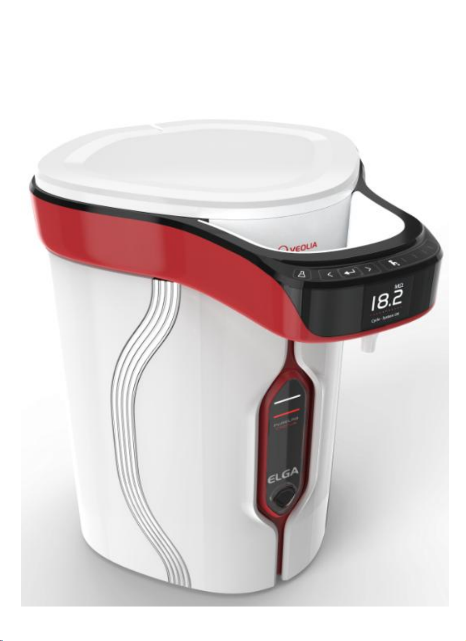
PURELAB
Configuration & Installation Guide
(PAF0076-01)
Chorus
Page 2

Contents
1. INTRODUCTION ................................................................................ 4
2. HEALTH & SAFETY ............................................................................ 4
3. AMMENDMENTS TO THIS DOCUMENT ............................................... 6
4. SYSTEM PART NUMBERS & DESCRIPTION ........................................ 6
5. CONSUMABLE COMPATABILITY ........................................................ 6
6. INSTALLATION KITS & PART DETAILS ............................................. 7
7. EXTERNAL ELECTRICAL, COMM’N & WATER CONNECTIONS .............. 9
8. INTERNAL ELECTRICAL & COMMUNICATION CONNECTIONS. ......... 10
Chorus 3 / PURELAB Chorus 2 or Microprocessor Board ............................................. 10
Storage Reservoir Microprocessor Board .................................................................. 11
Halo Dispense Microprocessor Board ....................................................................... 12
9. WALL MOUNTING KITS & MOUNTING CONFIGURATIONS ............... 13
1 x PURELAB Chorus 3 (RO) + 15, 30, 60 or 100 liter Storage Reservoir ..................... 17
2 x PURELAB Chorus 3 (30lph) + 15, 30, 60 or 100 liter Storage Reservoir ................. 18
3 x PURELAB Chorus 3 (30lph) + 60 or 100 liter Storage Reservoir ............................ 19
4 x PURELAB Chorus 3 (30lph) + 60 or 100 liter Storage Reservoir ............................ 20
1 x PURELAB Chorus 2 (RO/DI) + 15, 30, 60 or 100 liter Storage Reservoir ................. 21
2 x PURELAB Chorus 2 (RO/DI) + 15, 30, 60 or 100 liter Storage Reservoir ................. 22
3 x PURELAB Chorus 2 (RO/DI) + 60 or 100 liter Storage Reservoir ............................ 23
4 x PURELAB Chorus 2 (RO/DI) + 60 or 100 liter Storage Reservoir ............................ 24
10. PURELAB CHORUS 1 ....................................................................... 25
PURELAB Chorus 1 Range with Integrated Halo dispense ........................................... 25
PURELAB Chorus 1 Range with Remote Halo Dispense .............................................. 26
PURELAB Chorus 1 Range with multiple Halo Dispense solutions ................................. 27
11. GRAVITY FEED - HALO DISPENSE CONFIGURATIONS ..................... 28
1 x Halo Dispense (mounted remotely) ................................................................... 28
2 x Halo Dispensers (1 x integrated & 1 x mounted remotely) .................................... 29
2 Halo Dispensers (mounted remotely) ................................................................... 30
3 Halo Dispensers (1 x integrated & 2 x mounted remotely) ...................................... 31
3 Halo Dispensers (mounted remotely) ................................................................... 32
4 x Halo Dispensers (1 x integrated & 3 x mounted remotely) .................................... 33
4 x Halo Dispensers (mounted remotely) ................................................................. 34
12. PRESSURIZED FEED - HALO DISPENSE CONFIGURATIONS ............. 35
1 x Halo Dispense (mounted remotely) ................................................................... 35
2 x Halo Dispensers (1 x integrated & 1 x mounted remotely) .................................... 36
2 Halo Dispensers (mounted remotely) ................................................................... 37
3 Halo Dispensers (1 x integrated & 2 x mounted remotely) ...................................... 38
3 Halo Dispensers (mounted remotely) ................................................................... 39
4 x Halo Dispensers (1 x integrated & 3 x mounted remotely) .................................... 40
4 x Halo Dispensers (mounted remotely) ................................................................. 41
2
Page 3

Copyright Note
The information contained in this document is the property of VWS (UK) Ltd, trading as ELGA
LabWater, and is supplied without liability for errors or omissions.
No part of this document may be reproduced or used except as authorized by contract or other
written permission from VWS (UK) Ltd. The copyright and all restrictions on reproduction and use
apply to all media in which this information may be placed.
VWS (UK) Ltd. pursue a policy of continual product improvement and reserve the right to alter
without notice the specification, design, price or conditions of supply of any product or service.
© VWS (UK) Ltd. 2013 – All rights reserved.
ELGA
and PURELAB are registered trademarks of VWS (UK) Ltd.
3
Page 4
1. INTRODUCTION
WARNING!
WARNINGS ARE GIVEN WHERE FAILING TO
OBSERVE THE INSTRUCTIONS COULD RESULT IN
INJURY OR FATALITY.
CAUTION!
Cautions are given where failure to observe the
instructions could result in damage to the
equipment, associated equipment and processes.
CAUTION!
Clean dry indoor. Temp 5-40°C.
Humidity max 80% non-condensing.
Failure to follow the environmental specification
could result in damage to the system.
PURELAB Chorus is not designed for use in fume
cupboards where chemicals could damage the
system.
CAUTION!
The Halo Flexible Dispense handset is not
designed to be submersed in water.
WARNING!
ONLY USE THE APPLIANCE COUPLER (MAINS
LEAD), POWER SUPPLY AND COMMUNICATIONS
LEADS PROVIDED.
THE USE OF THESE WILL ENSURE ADEQUATE
EARTH PROTECTION IS PROVIDED.
IF THE EQUIPMENT IS USED IN A MANNER NOT
SPECIFIED BY ELGA, THE PROTECTION PROVIDED
BY THE EQUIPMENT MAY BE IMPAIRED
POSITION THE POWER SUPPLY SO THAT IT
CANNOT COME INTO CONTACT WITH WATER.
This Configuration guide has been prepared to illustrate best practice when configuring PURELAB
Chorus. Please adhere to the following safety instructions.
2. HEALTH & SAFETY
Environment
Halo Dispense
Electricity
The appliance coupler (mains lead) or power supply connected to the rear of the unit can be
removed to isolate the power supply. If access to this is restricted then it is recommended that
access to the supply socket is easily available to disconnect the electrical supply.
4
Page 5

WARNING!
UNDER NO CIRCUMSTANCES SHOULD THE LAMP BE
CONNECTED AND ACTIVATED WHEN OUTSIDE THE
HOUSING. EXPOSURE COULD CAUSE SERIOUS
INJURY TO EYES AND SKIN.
ENSURE THE UV LAMP IS DISPOSED OF IN
ACCORDANCE WITH LOCAL REGULATIONS.
WARNING!
DURING THE COMMISSIONING CYCLE TRACE
RESIDUAL BIOSTAT IS FLUSHED FROM THE
SYSTEM. A MATERIAL SAFETY DATA SHEET IS
AVAILABLE UPON REQUEST.
Ultraviolet Light
Residual Biostat
Control of Substances Hazardous to Health (COSHH)
Material safety data sheets covering the various replaceable Purification Packs are available upon
request.
5
Page 6
3. AMMENDMENTS TO THIS DOCUMENT
Issue
No.
Details of Amendment
1
Released at Issue 1 – 07/11/2013
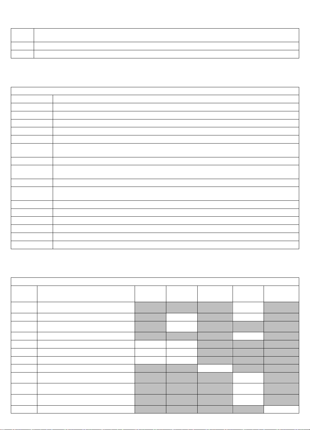
System Part Numbers & Description
Part No.
Description
PC1ANRXM1
PURELAB Chorus 1 – Type I Ultrapure solution for Analytical Research Applications
PC1LCSXM1
PURELAB Chorus 1 - Type I Ultrapure solution for Life Science Applications
PC1GSCXM1
PURELAB Chorus 1 - Type I Ultrapure solution for General Science Applications
PC2RODIM1
PURELAB Chorus 2 (RO/DI) – Tap to Pure Water System
RO310XXM1
PURELAB Chorus 3 (RO) – Type III General Grade Solution up to 10l/hr
RO310BPM1
PURELAB Chorus 3 (RO) – Type III General Grade Solution up to 10l/hr.
(fitted with feed water boost pump)
RO320XXM1
PURELAB Chorus 3 (RO) – Type III General Grade Solution up to 20l/hr
RO320BPM1
PURELAB Chorus 3 (RO) – Type III General Grade Solution up to 20l/hr.
(fitted with feed water boost pump)
RO330XXM1
PURELAB Chorus 3 (RO) – Type III General Grade Solution up to 30l/hr
RO330BPM1
PURELAB Chorus 3 (RO) – Type III General Grade Solution up to 30l/hr.
(fitted with feed water boost pump)
LA754
Halo Dispenser
LA755
Halo Advanced Dispenser
LA756
Halo Flexible Dispenser
LA757
15 Liter Storage Reservoir
LA758
30 Liter Storage Reservoir
LA759
60 Liter Storage Reservoir
System Part Numbers & Description
Part No.
Description
Chorus 3
(RO)
PURELAB
Chorus 2
(RO/DI)
Storage
Reservoirs
PURELAB
Chorus
1
Halo
Dispensers
LC232
Purification Pack (RO Feed) – PURELAB
Chorus 1
- - - ✓ -
LC233
Bypass Pack
- ✓ - ✓ -
LC234
Purification pack - PURELAB Chorus 2
RO/DI
- ✓ - - -
LC236
Sanitization Pack (Standard)
- - - ✓ -
LC239
Degassing Module
✓
✓
- -
LC240
RO Module (10l/hr)
✓
✓
- - -
LC241
Pre-treatment Pack
✓
✓
- - -
LC242
Composite Vent Filter
-
- ✓ -
-
LC244
Purification Pack (SDI feed) – PURELAB
Chorus 1
- - - ✓ -
LC245
Purification Pack (Low Ionic) – PURELAB
Chorus 1
- - - ✓ -
LC246
Purification Pack – (Low TOC) PURELAB
Chorus 1
- - - ✓ -
LC145
Point-of-Use - 0.2μm Microfilter
- - -
-
✓
4. SYSTEM PART NUMBERS & DESCRIPTIONS
5. CONSUMABLE COMPATABILITY
6
Page 7
6. INSTALLATION KITS & PART DETAILS
LC197
Point-of-Use - Biofilter
- - -
-
✓
LC210
UV Lamp (185/254nm)
- - -
✓*
-
LC109
Ultra Micro Filter
- - -
✓**
-
LC151
Ultra Filter
- - -
✓***
-
*
Not compatible with PURELAB Chorus 1 – General Science
**
Not compatible with PURELAB Chorus 1 – General Science or Life Science
***
Not compatible with PURELAB Chorus 1 – General Science or Analytical Research
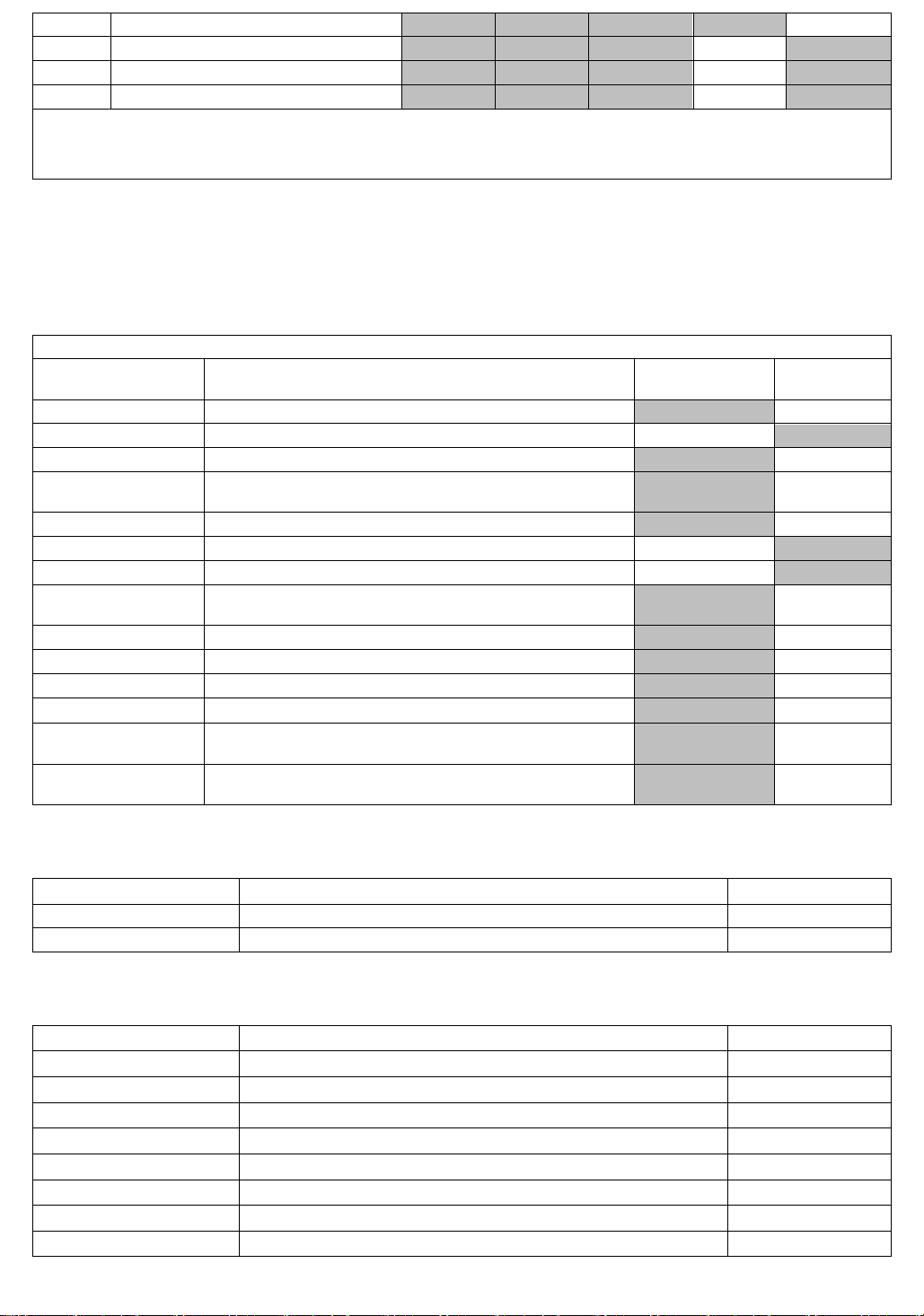
Parts / Installation Kits Required
Part No.
Description
Supplied
with System
Ordered
Separately
CEPWGU303754
Power Supply
-
✓
LA762
Standard Installation Kit
✓
-
LA768
Halo Dispense Wall Mounting Kit
✓
LA770
Wall Mounting Kit – 15 & 30 ltr Storage
Reservoirs
✓
LA771
Wall Mounting Kit – 60 ltr Storage Reservoirs
✓
LA773
Reservoir Installation Kit
✓
-
LA774
Halo Installation Kit
✓
-
LA775
Degassing Kit (Chorus 3 (RO) and
PURELAB Chorus 2 (RO/DI))
-
✓
LA776
Tool Kit
-
✓
LA777
Integrated Installation Kit
-
✓
LA778
Side By Side Installation Kit
-
✓
LA779
Remote Mounted Installation Kit
-
✓
LA575
Pressure Regulator – See feed water pressure
guidelines for each configuration
-
✓
LA732
Footswitch Dispense – Compatible with Halo
Advanced and Halo Flexible Dispense only.
-
✓
Part Number
Description
Qty
FTBEAC0505
FLOW BEND JG 5/16"
10
TUBE31957
TUBING JG 8MM OD X 5MM ID
5
Part Number
Description
Qty
FTBEAC0505
FLOW BEND JG 5/16"
5
FTELAC201660
ELBOW STEM 15MM OD TUBE (ACETAL BLACK)
1
FTSPPP302252
DISPENSE TAP HPSBC - BLACK WITH CHROME BONNET
1
INST40010
INSTALLATION SETUP GUIDE - RESERVOIR RANGE
1
LC216
COMPOSITE VENT FILTER ASSEMBLY
1
LEAD40029
5.0 MTR RS485 CROSSOVER LEAD
1
TUBE31957
TUBING JG 8MM OD X 5MM ID
5
VABLAC0040
VALVE ISOLATING 8MM
2
The following pages detail what is contained in PURELAB Chorus Installation Kits to help you locate
the correct parts for installation.
LA762 Standard Installation Kit
For use with all systems, this should be used in addition to one of the following installation kits.
LA773 Reservoir Installation Kit
For use with all 15,30,60 & 100 ltr Storage Reservoirs.
7
Page 8
Part Number
Description
Qty
FTBEAC0505
FLOW BEND JG 5/16"
2
FXSCYR302246
SCREW M8 X 110MM SOCKET CAP HEAD A4 S/STL
1
TUBE31957
TUBING JG 8MM OD X 5MM ID
5
Part Number
Description
Qty
CECVGU304974
COVER YELLOW PVC 11.9MM X 12.7MM
2
FXBOYR301716
BOLT M8x45mm SOCKET HEX KEY ST/ST
1
FXCLGU302927
CLIP WALL SECURING
1
LEAD39872
RS485 600MM RED CROSSOVER CABLE
1
SP1010
WIRING SET STANDARD INSTALLATION KIT
1
TEES38261
EQUAL TEE - 8MM OD TUBE
2
Part Number
Description
Qty
LEAD39873
RS485 1.5M BLACK CROSSOVER CABLE
1
LEAD39874
1.5MTR EXTERNAL POWER LEAD
1
TEES38261
EQUAL TEE - 8MM OD TUBE
2
Part Number
Description
Qty
FTBEAC0505
FLOW BEND JG 5/16"
2
LEAD40029
5.0 MTR RS485 CROSSOVER LEAD
1
LEAD40175
5.0 MTR EXTERNAL POWER LEAD
1
TUBE31957
TUBING JG 8MM OD X 5MM ID
10
Part Number
Description
Qty
TOTOGU0510
Tube Cutter
1
TOTOGU1305
PTFE Tape
1
TOTGU1605
John Guest Collet Release Tools
1
TOTOGU303630
6mm Hex Key
1
LA774 Dispense Installation Kit
For installing a Halo Dispenser, attached directly to a PURELAB Chorus system.
LA777 Integrated Installation Kit
For installing 2 integrated PURELAB Chorus systems
LA778 Side By Side Installation Kit
For installing multiple PURELAB Chorus systems side by side
LA779 Remote Mounted Installation Kit
For installing a Halo Dispenser remotely up to 5m away from the PURELAB Chorus system.
LA776 Chorus Tool Kit
Tools required for installing a system if not installed by a Service Technician.
8
Page 9
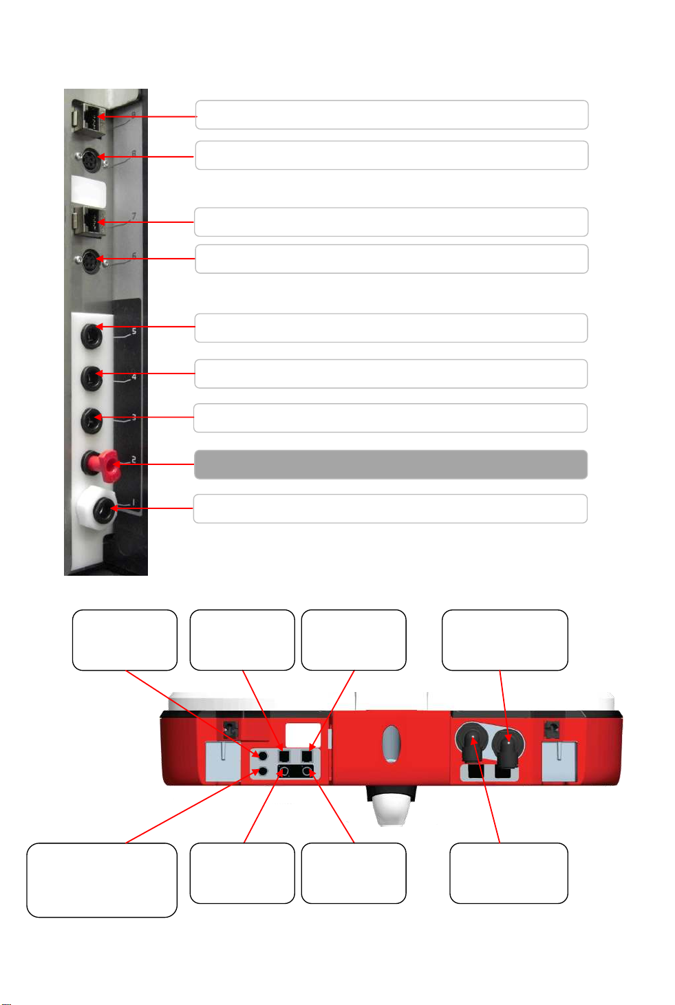
7. EXTERNAL ELECTRICAL, COMM’N & WATER CONNECTIONS
Port 1 - Water Inlet (all systems)
Port 2 – Not Used
Port 3 – Drain Outlet (all Systems)
Port 4 – Purified Water Outlet (all systems)
Port 5 – Return – Purified Water (PURELAB Chorus 1 only)
Port 9
Network
Connection
Port 7
Network
Connection
Port 8
Power
Connection
Port 6
Power
Connection
Port 5
Purified Water
Return
Port 1
Purified Water
Inlet
Port 6 – Electrical Power (all systems)
Port 7 – Network Connection (all systems)
Port 8 – Electrical Power (all systems)
Port 9 – Network Connection (all systems)
Port 11
BMS
Connection
Port 10
Footswitch
Connection
(Halo Advanced Only)
PURELAB Chorus Range
Halo Dispense
9
Page 10
8. INTERNAL ELECTRICAL & COMMUNICATION CONNECTIONS.
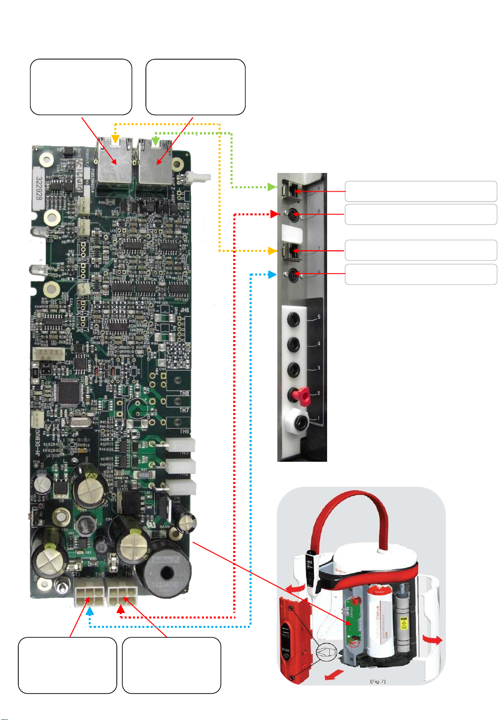
J2
Network
Connection
(External Port 7)
TH5
Power
Connection
(External Port 6)
J1
Network
Connection
(External Port 9)
TH4
Power
Connection
(External Port 8)
Port 6 – Electrical Power
Port 7 – Network Connection
Port 8 – Electrical Power
Port 9 – Network Connection
Chorus 3 / PURELAB Chorus 2 or Microprocessor Board
10
Page 11
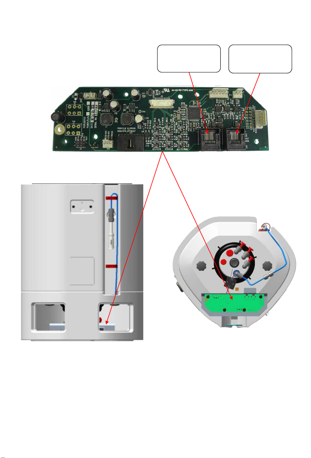
Storage Reservoir Microprocessor Board
J2
Network & Power
Connection
J1
Network & Power
Connection
11
Page 12
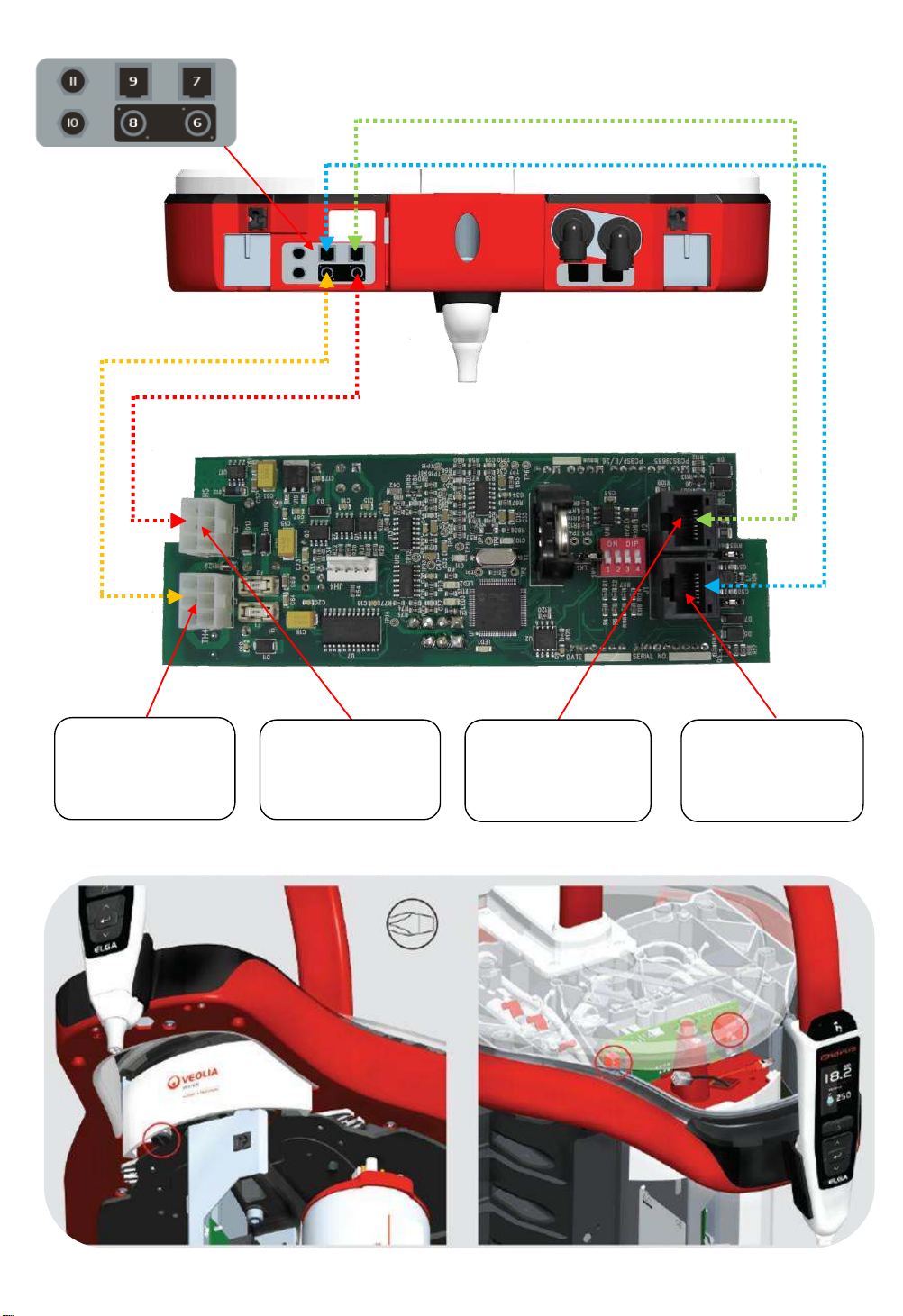
Halo Dispense Microprocessor Board
J2
Network
Connection
(External Port 7)
J1
Network
Connection
(External Port 9)
TH5
Power
Connection
(External Port 6)
TH4
Power
Connection
(External Port 8)
12
Page 13
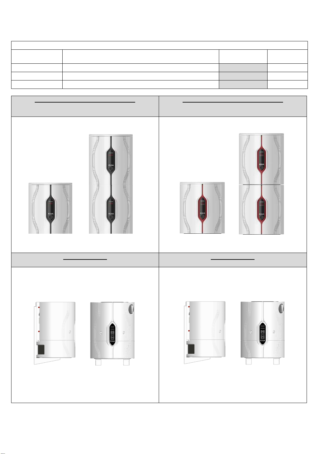
9. WALL MOUNTING KITS & MOUNTING CONFIGURATIONS
Bench Mounted / Wall Mounted
Independent Chorus 3 (RO)
Up to 2 systems can be mounted together
Bench Mounted / Wall Mounted
Independent PURELAB Chorus 2 (RO/DI)
Up to 2 systems can be mounted together
No wall mounting kit required
No wall mounting kit required
Wall Mounted
Independent 15 /30 liter Storage Reservoir
Wall Mounted
Independent 60 liter Storage Reservoir
Use LA770 Wall Mounting Kit
Use LA771 Wall Mounting Kit
Parts / Installation Kits Required
Part No.
Description
Supplied
with System
Ordered
Separately
LA768
Wall Mounting Kit – Halo Dispense Solutions
- ✓ LA770
Wall Mounting Kit – 15 & 30 ltr Storage Reservoirs
-
✓
LA771
Wall Mounting Kit – 60 ltr Storage Reservoirs
-
✓
The following page details what is contained in PURELAB Chorus Installation Kits to help you locate
the correct parts for installation.
13
Page 14
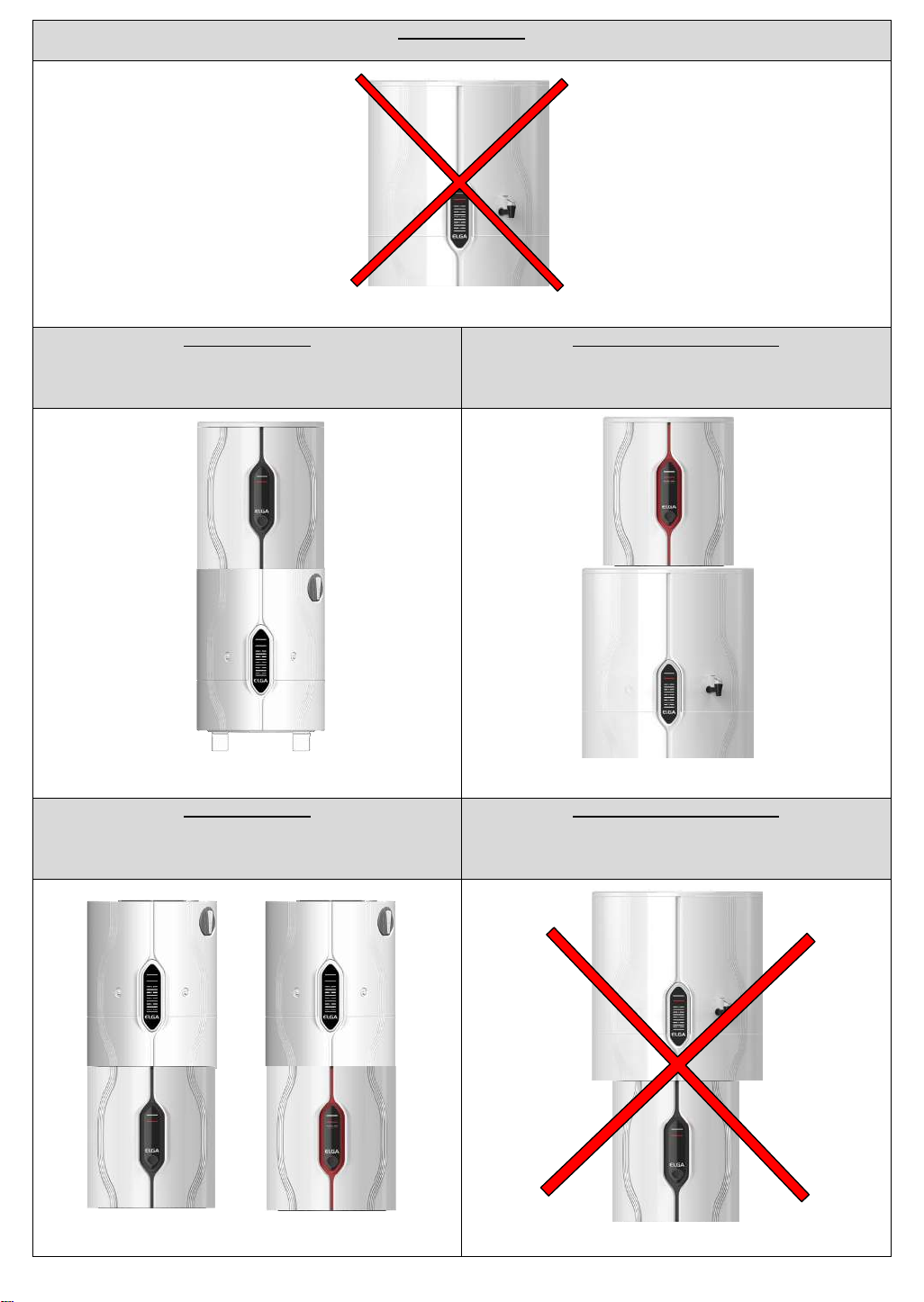
Wall Mounted
Independent 100 liter Storage Reservoir
It is not possible to wall mount the 100 liter Storage reservoir on a wall.
Wall Mounted
Chorus 3 (RO) or PURELAB Chorus 2
(RO/DI) with 15 or 30 liter Storage
Reservoir Integrated underneath
Bench / Wall Mounted
Chorus 3 (RO) or PURELAB Chorus 2
(RO/DI) with 60 Storage Reservoir
Integrated underneath
Use LA770 Wall Mounting Kit
Use LA771 Wall Mounting Kit
Wall Mounted
Chorus 3 (RO) or PURELAB Chorus 2
(RO/DI) with 15 or 30 liter Storage
Reservoir Integrated on top
Bench / Wall Mounted
Chorus 3 (RO) or PURELAB Chorus 2
(RO/DI) with 60 or 100 liter Storage
Reservoir Integrated on top
No wall mounting kit is required
This configuration is not possible
14
Page 15
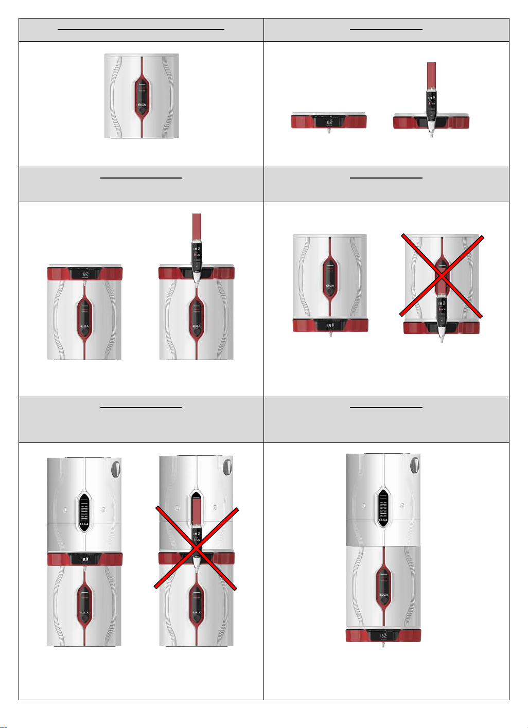
Bench Mounted / Wall Mounted
Independent PURELAB Chorus 1 Range
Wall Mounted
Independent Halo Dispense
No wall mounting kit required
Use LA768 Wall Mounting Kit
Bench Mounted
PURELAB Chorus 1 with Halo Dispense
Integrated on top
Wall Mounted
PURELAB Chorus 1 with Halo Dispense
Integrated Underneath
No wall mounting kit required
No wall mounting kit required
Halo Flexible Dispense configuration is not
possible. possible
Bench Mounted
PURELAB Chorus 1 with Halo Dispense and
15 or 30 liter Storage Reservoir Integrated
on top
Wall Mounted
PURELAB Chorus 1 with Halo Dispense
Integrated Underneath and 15 or 30 liter
reservoir Integrated on top
No wall mounting kit required
Halo Flexible Dispense configuration is not
possible.
No wall mounting kit required
This installation is mounted using PURELAB
Chorus 1. The Halo Mounting Kit (LA768)
must not be used
15
Page 16
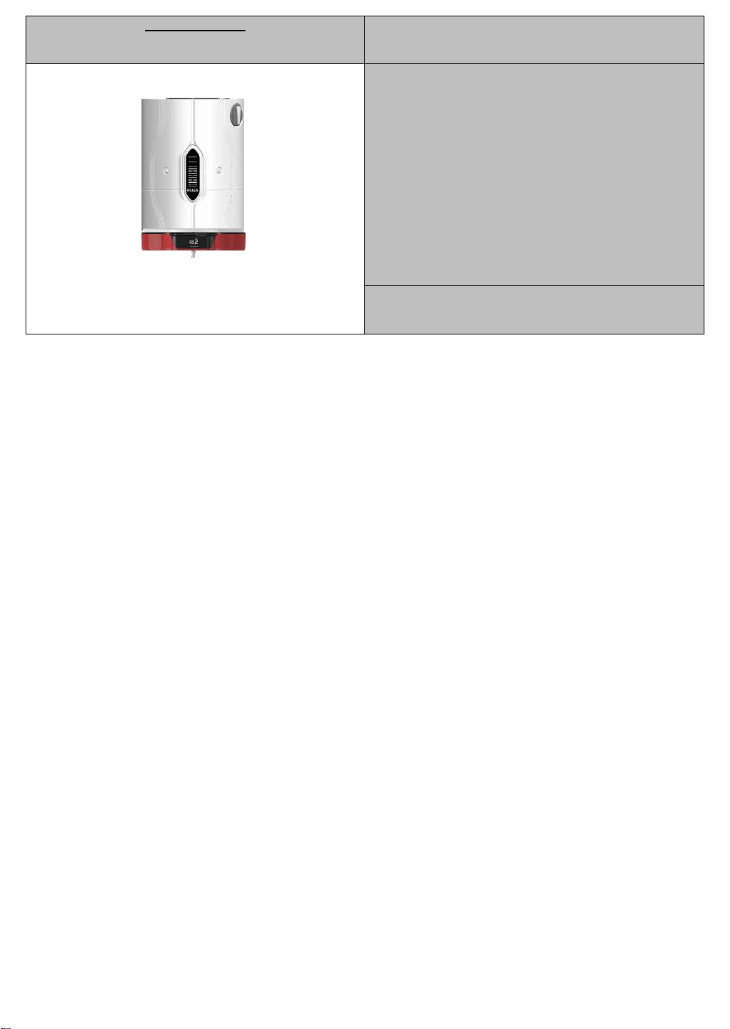
Wall Mounted
Halo Dispense with integrated 15 or 30 liter
reservoir Integrated on top
-
-
Use LA768 Wall Mounting Kit and additional
mounting bracket supplied to secure reservoir to
the wall.
16
Page 17
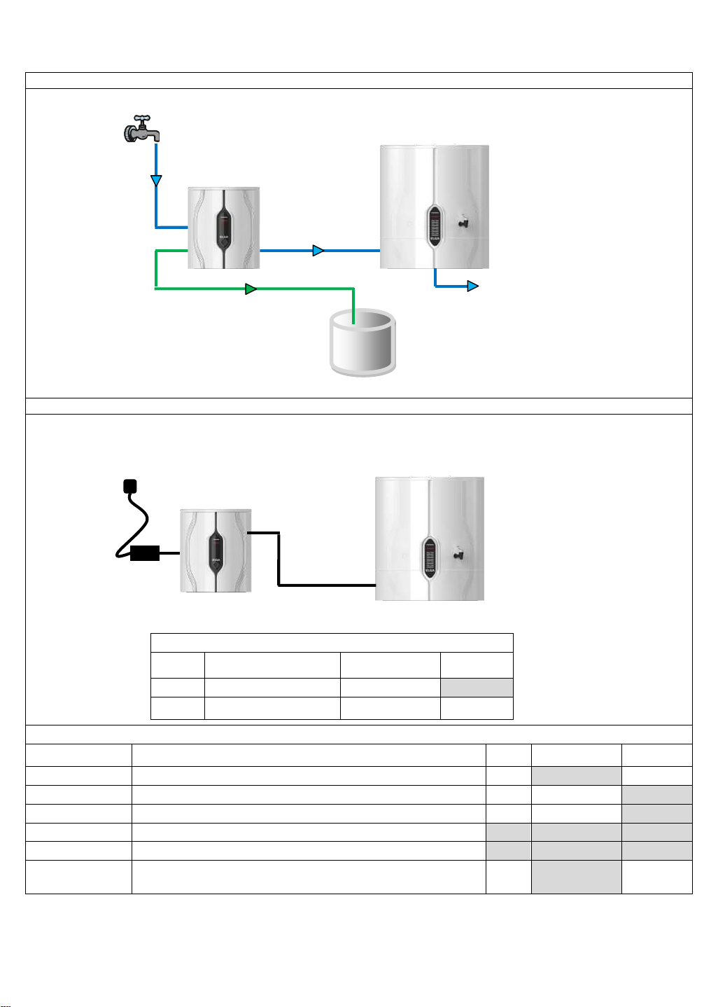
1 x PURELAB Chorus 3 (RO) + 15, 30, 60 or 100 liter Storage
Hydraulic / Water Connections
Electrical / Communications Connections
Communication / Power Connection Details
Colour
Description
System 1
Connection No.
Storage
Reservoir
Black
Power Cable
6
-
Black
External Comm’n &
Power Cable
7
J2
Parts / Installation Kits Required
Part No.
Description
QTY
Supplied with
System
Ordered
Separately
CEPWGU303754
Power Supply
1
-
✓
LA762
Standard Installation Kit
1
✓
-
LA773
Reservoir Installation Kit
1 ✓ -
LA777
Integrated Installation Kit
- - -
LA778
Side By Side Installation Kit
- - -
LA652
Pressure Regulator
With Boost Pump – Fitted when inlet pressure >2.0bar (30psi).
Without Boost pump – Fitted when inlet pressure >6.0bar (90psi).
1
-
✓
Power
Supply
External
Communication
& Power Cable
Inlet
Outlet
Drain
1
3
4
1
6
7
J2
System 1
Storage
Reservoir
4a
Outlet
Reservoir
17
Page 18
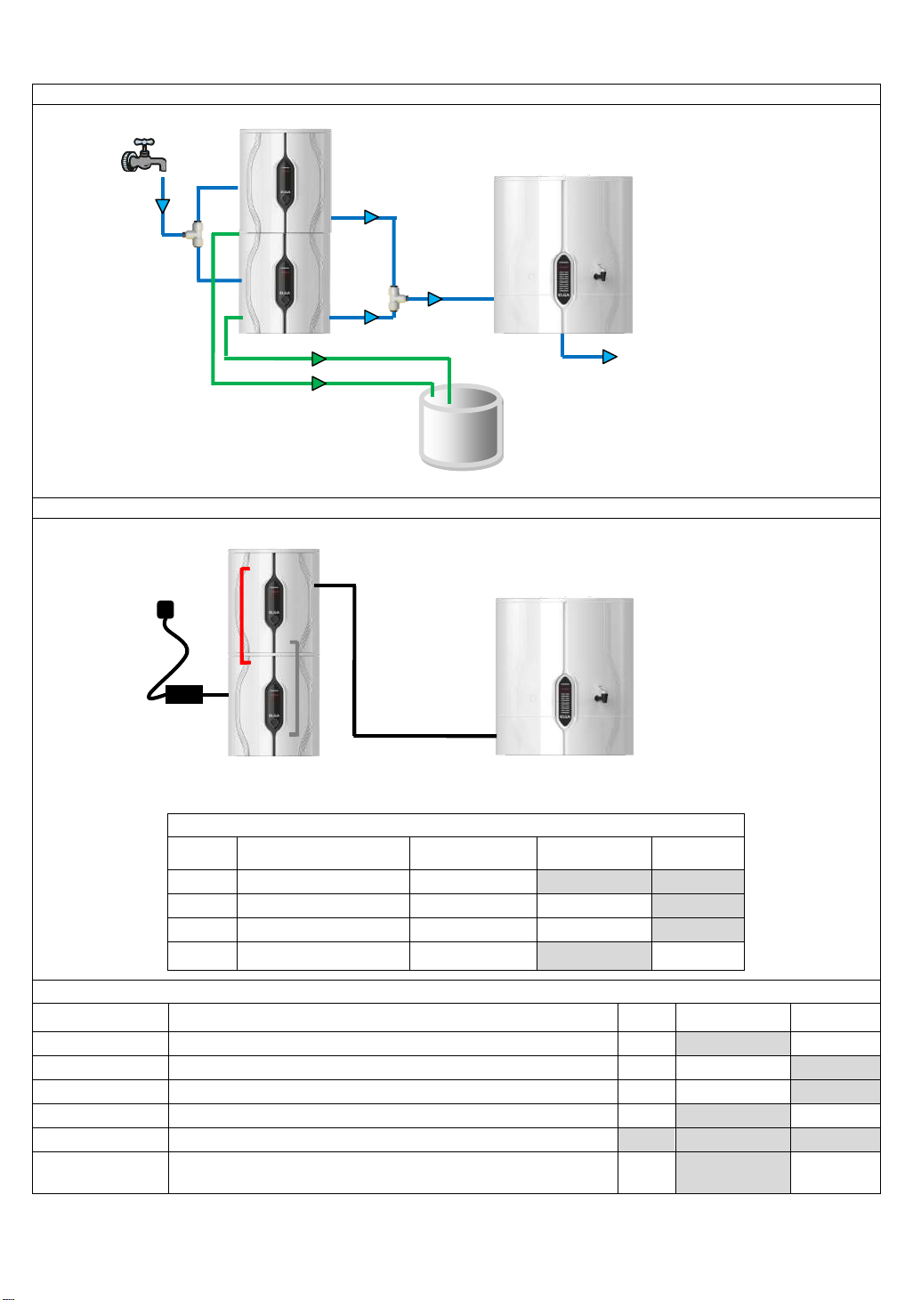
2 x PURELAB Chorus 3 (30lph) + 15, 30, 60 or 100 liter Storage
Hydraulic / Water Connections
Electrical / Communications Connections
Communication / Power Connecion Details
Colour
Description
System 1
Connection No.
System 2
Connection No.
Storage
Reservoir
Black
Power Cable
6 - -
Red
Internal Comm’n Cable
J2
J2
-
Grey
Internal Power Cable
TH4
TH4
-
Black
External Comm’n &
Power Cable
9 - J2
Parts / Installation Kits Required
Part No.
Description
QTY
Supplied with
System
Ordered
Separately
CEPWGU303754
Power Supply
1
-
✓
LA762
Standard Installation Kit
1
✓
-
LA773
Reservoir Installation Kit
1 ✓ -
LA777
Integrated Installation Kit
1
-
✓
LA778
Side By Side Installation Kit
-
-
-
LA652
Pressure Regulator
With Boost Pump – Fitted when inlet pressure >2.0bar (30psi).
Without Boost pump – Fitted when inlet pressure >6.0bar (90psi).
1
-
✓
Power
Supply
Inlet
Outlet
Drain
6 9 J2 1 4
4
1
1 3 3
System 1
System 2
J2
TH4
J2
TH4
TH4
Storage
Reservoir
External
Communication
& Power Cable
4a
Outlet
Reservoir
18
Page 19
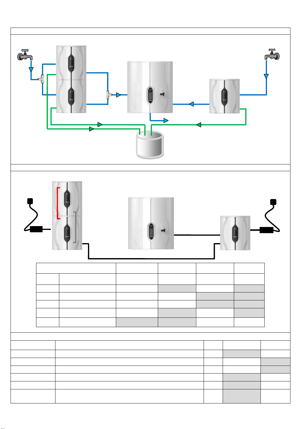
3 x PURELAB Chorus 3 (30lph) + 60 or 100 liter Storage
Hydraulic / Water Connections
Electrical / Communications Connections
Communication / Power
Connection Details
Colour
Description
System 1
Connection No.
System 2
Connection No.
System 3
Connection No.
Storage
Reservoir
Black
Power Cable
6 - 6
-
Red
Internal Comm’n Cable
J2
J2 - -
Grey
Internal Power Cable
TH4
TH4 - -
Black
External Comm’n &
Power Cable
7 - 7
-
Black
External Comm’n &
Power Cable
- - 9
J2
Parts / Installation Kits Required
Part No.
Description
QTY
Supplied with
System
Ordered
Separately
CEPWGU303754
Power Supply
2
- ✓ LA762
Standard Installation Kit
3
✓
-
LA773
Reservoir Installation Kit
1 ✓ -
LA777
Integrated Installation Kit
1
-
✓
LA778
Side By Side Installation Kit
1
-
✓
LA652
Pressure Regulator
With Boost Pump – Fitted when inlet pressure >2.0bar (30psi).
Without Boost pump – Fitted when inlet pressure >6.0bar (90psi).
2
-
✓
System 2
Power
Supply
6
J2
System 1
System 3
7 7 6
1
4
1
1
4
Drain
3
3
5 4 1
3
9
Inlet
Outlet
Inlet
Outlet
J2
J2
TH4
TH4
Storage
Reservoir
External
Communication
& Power Cable
External
Communication
& Power Cable
4a
Outlet
Reservoir
19
Page 20
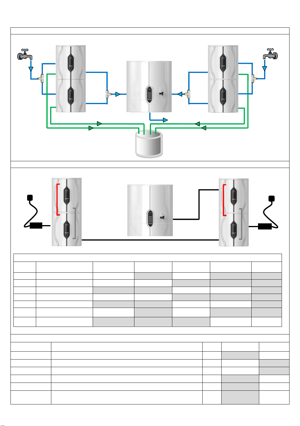
4 x PURELAB Chorus 3 (30lph) + 60 or 100 liter Storage
Hydraulic / Water Connections
Electrical / Communications Connections
Communication / Power Connection Details
Colour
Description
System 1
Connection No.
System 2
Connection No.
System 3
Connection No.
System 4
Connection No.
Storage
Reservoir
Black
Power Cable
6 - 6 -
Red
Internal Comm’n Cable
J2
J2 - -
-
Red
Internal Comm’n Cable
- - J2
J2
-
Grey
Internal Power Cable
TH4
TH4 - -
-
Grey
Internal Power Cable
- - TH4
TH4
-
Black
External Comm’n &
Power Cable
7 - 7 - -
Black
External Comm’s &
Power Cable
- - - 7 J2
Parts / Installation Kits Required
Part No.
Description
QTY
Supplied with
System
Ordered
Separately
CEPWGU303754
Power Supply
2
-
✓
LA762
Standard Installation Kit
4
✓
-
LA773
Reservoir Installation Kit
1 ✓ -
LA777
Integrated Installation Kit
2
-
✓
LA778
Side By Side Installation Kit
1
-
✓
LA652
Pressure Regulator
With Boost Pump – Fitted when inlet pressure >2.0bar (30psi).
Without Boost pump – Fitted when inlet pressure >6.0bar (90psi).
2
-
✓
System 2
7
Power
Supply
6
J2
System 1
System 4
System 3
7
7
6
1
4
1
1
4
Drain
3
3 5 4 4 1 1 3
3
Inlet
Outlet
Inlet
Outlet
J2
J2
TH4
TH4
J2
J2
TH4
TH4
Storage
Reservoir
External
Communication
& Power Cable
External
Communication
& Power Cable
4a
Outlet
Reservoir
20
Page 21
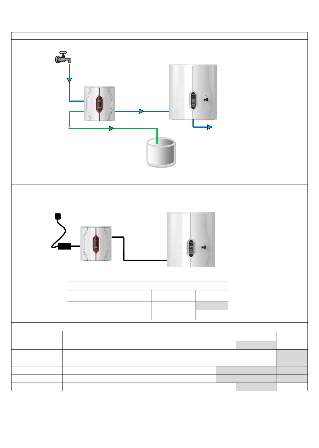
1 x PURELAB Chorus 2 (RO/DI) + 15, 30, 60 or 100 liter Storage
Hydraulic / Water Connections
Electrical / Communications Connections
Communication / Power Connction Dtails
Colour
Description
System 1
Connection No.
Storage
Reservoir
Black
Power Cable
6
-
Black
External Comm’n &
Power Cable
J2
J2
Parts / Installation Kits Required
Part No.
Description
QTY
Supplied with
System
Ordered
Separately
CEPWGU303754
Power Supply
1
-
✓
LA762
Standard Installation Kit
1
✓
-
LA773
Reservoir Installation Kit
1 ✓ -
LA777
Integrated Installation Kit
- - -
LA778
Side By Side Installation Kit
- - -
LA652
Pressure Regulator – Fitted when inlet pressure >2.0bar (30psi)
1
-
✓
Power
Supply
Inlet
Outlet
Drain
1
3
4
1
6
7
J2
System 1
Storage
Reservoir
External
Communication
& Power Cable
Outlet
4a
Reservoir
21
Page 22
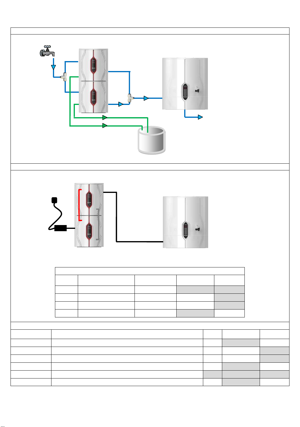
2 x PURELAB Chorus 2 (RO/DI) + 15, 30, 60 or 100 liter Storage
Hydraulic / Water Connections
Electrical / Communications Connections
Communication / Power Connectin Details
Colour
Description
System 1
Connection No.
System 2
Connection No.
Storage
Reservoir
Black
Power Cable
6 - -
Red
Internal Comm’n Cable
J2
J2
-
Grey
Internal Power Cable
TH4
TH4
-
Black
External Comm’n Cable
9 - J2
Parts / Installation Kits Required
Part No.
Description
QTY
Supplied with
System
Ordered
Separately
CEPWGU303754
Power Supply
1
-
✓
LA762
Standard Installation Kit
1
✓
-
LA773
Reservoir Installation Kit
1 ✓ -
LA777
Integrated Installation Kit
1
-
✓
LA778
Side By Side Installation Kit
-
-
-
LA652
Pressure Regulator – Fitted when inlet pressure >2.0bar (30psi)
1
-
✓
Power
Supply
Inlet
Outlet
Drain
6 9 J2 1 4
4
1
1 3 3
System 1
System 2
J2
J2
TH4
TH4
Storage
Reservoir
External
Communication
& Power Cable
4a
Outlet
Reservoir
22
Page 23
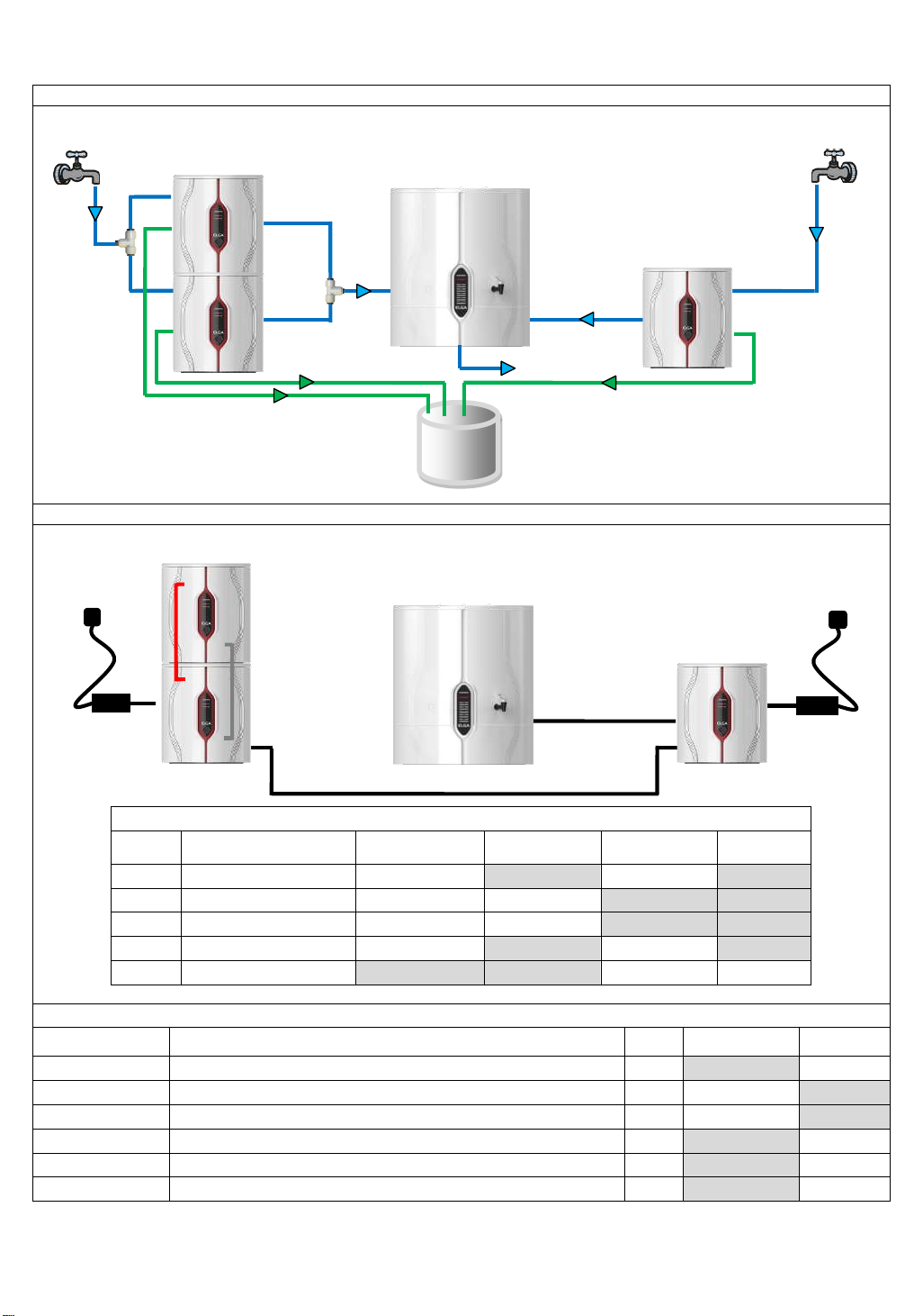
3 x PURELAB Chorus 2 (RO/DI) + 60 or 100 liter Storage
Hydraulic / Water Connections
Electrical / Communications Connections
Communication / Power Connection Details
Colour
Description
System 1
Connection No.
System 2
Connection No.
System 3
Connection No.
Storage
Reservoir
Black
Power Cable
6 - 6
-
Red
Internal Comm’n Cable
J2
J2 - -
Grey
Internal Power Cable
TH4
TH4 - -
Black
External Comm’n Cable
7 - 7
-
Black
External Comm’n Cable
- - 9
J2
Parts / Installation Kits Required
Part No.
Description
QTY
Supplied with
System
Ordered
Separately
CEPWGU303754
Power Supply
2
- ✓ LA762
Standard Installation Kit
3
✓
-
LA773
Reservoir Installation Kit
1 ✓ -
LA777
Integrated Installation Kit
1
-
✓
LA778
Side By Side Installation Kit
1
- ✓ LA652
Pressure Regulator – Fitted when inlet pressure >2.0bar (30psi)
2
-
✓
System 2
Power
Supply
6
J2
System 1
System 3
7
7 6 1
4
1
1
4
Drain
3
3
5 4 1
3
Inlet
Outlet
Inlet
Outlet
J2
J2
TH4
TH4
9
Storage
Reservoir
External
Communication
& Power Cable
External
Communication
& Power Cable
4a
Outlet
Reservoir
23
Page 24
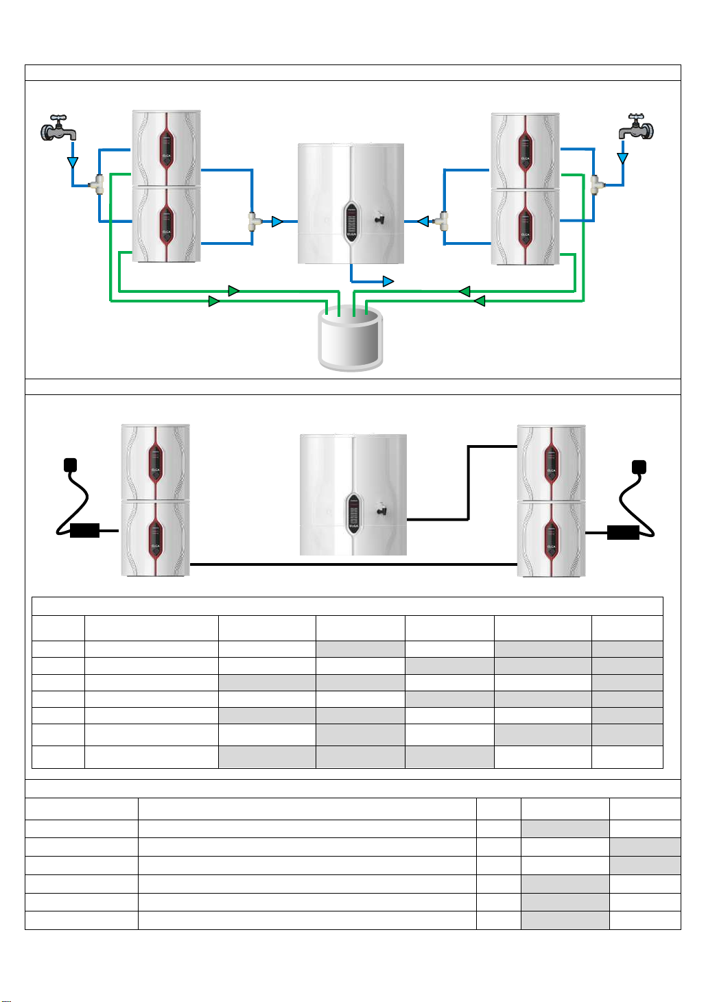
4 x PURELAB Chorus 2 (RO/DI) + 60 or 100 liter Storage
Hydraulic / Water Connections
Electrical / Communications Connections
Commnication / Power Connection Details
Colour
Description
System 1
Connection No.
System 2
Connection No.
System 3
Connection No.
System 4
Connection No.
Storage
Reservoir
Black
Power Cable
6 - 6 -
Red
Internal Comm’n Cable
J2
J2 - -
-
Red
Internal Comm’n Cable
- - J2
J2
-
Grey
Internal Power Cable
TH4
TH4 - -
-
Grey
Internal Power Cable
- - TH4
TH4
-
Black
External Comm’n &
Power Cable
7 - 7 - -
Black
External Comm’n &
Power Cable
- - - 7 J2
Parts / Installation Kits Required
Part No.
Description
QTY
Supplied with
System
Ordered
Separately
CEPWGU303754
Power Supply
2
-
✓
LA762
Standard Installation Kit
4
✓
-
LA773
Reservoir Installation Kit
1 ✓ -
LA777
Integrated Installation Kit
2
-
✓
LA778
Side By Side Installation Kit
1
-
✓
LA652
Pressure Regulator – Fitted when inlet pressure >2.0bar (30psi)
2
-
✓
7
System 2
7
Power
Supply
6
J2
System 1
System 4
System 3
7
1
4
1
1
4
Drain
3
3 5 4 4 1 1 3
3
Inlet
Outlet
Inlet
Outlet
Storage
Reservoir
External
Communication
& Power Cable
External
Communication
& Power Cable
4a
Outlet
Reservoir
24
Page 25
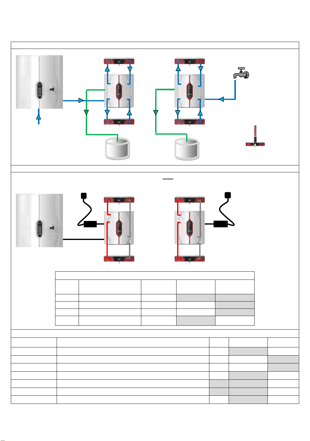
10. PURELAB CHORUS 1
Hydraulic / Water Connections
Electrical / Communications Connections
Communication / Power Connection Details
Colour
Description
System 1
Connection
No.
Halo Dispense
1
Connection No.
Storage
Reservoir
Connection No.
Black
Power Cable
6 - -
Red
Internal Comm’n Cable
J2
J1
-
Grey
Internal Power Cable
TH4
TH4
-
Black
External Comm’n &
Power Cable
7 - J2
Parts / Installation Kits Required
Part No.
Description
QTY
Supplied with
System
Ordered
Separately
CEPWGU303754
Power Supply
1
-
✓
LA762
Standard Installation Kit
1
✓
-
LA774
Halo Dispense Installation Kit
1 ✓ -
LA777
Integrated Installation Kit
1
-
✓
LA778
Side By Side Installation Kit
-
- ✓ LA779
Remote Installation Kit
-
-
✓
LA575
Pressure Regulator – Fitted when inlet pressure = >0.7bar (10psi)
1
-
✓
7
Power
Supply
6
J2
Drain
4a
1
Inlet
Power
Supply
6
1. Connected to a Storage Reservoir
1. NOT connected to a Storage Reservoir
1
1
5
1
5
Drain
1 5 1
5
4
5
3
3
4
5
Note: Drain connection 3 is
required for Life Science and
Analytical Research variants
only.
J2
TH4
J1
TH4
J1
TH4
J1
TH4
J1
TH4
J2
TH4
Note: Halo Flexible Dispense
will not integrate underneath
PURELAB Chorus System
Storage
Reservoir
External
Communication
& Power Cable
1
Inlet
PURELAB Chorus 1 Range with Integrated Halo dispense
25
Page 26
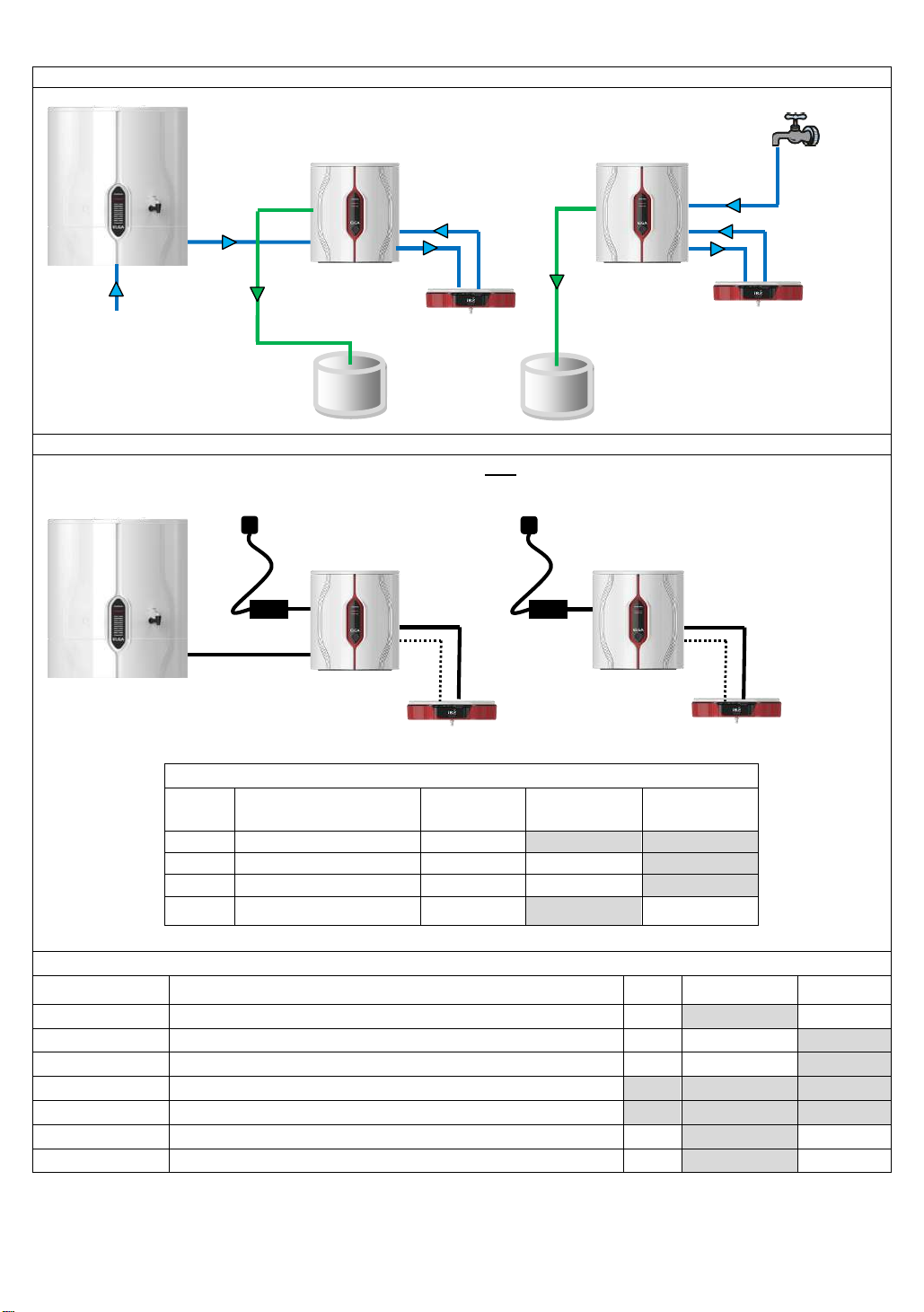
PURELAB Chorus 1 Range with Remote Halo Dispense
Hydraulic / Water Connections
Electrical / Communications Connections
Communication / Power Connection Details
Colour
Description
System 1
Connection
No.
Halo Dispense
1
Connection No.
Storage
Reservoir
Connection No
Black
Power Cable
6 - -
Black
External Comm’n Cable
9 7 -
Black
External Power Cable
8 6 -
Black
External Comm’n &
Power Cable
7 - J2
Parts / Installation Kits Required
Part No.
Description
QTY
Supplied with
System
Ordered
Separately
CEPWGU303754
Power Supply
1
- ✓ LA762
Standard Installation Kit
1
✓
-
LA774
Halo Dispense Installation Kit
1 ✓ -
LA777
Integrated Installation Kit
- - -
LA778
Side By Side Installation Kit
- - -
LA779
Remote Installation Kit
1
- ✓ LA575
Pressure Regulator – Fitted when inlet pressure = >0.7bar (10psi)
1
-
✓
7
Power
Supply
6
J2
Drain
4a
1
Inlet
Power
Supply
1. Connected to a Storage Reservoir
1. NOT connected to a Storage Reservoir
1
1
5
Drain
4
5
3
3
Note: Drain connection 3 is
required for Life Science and
Analytical Research variants
only.
Storage
Reservoir
7
6
9
8 7 6
9
8
6
System 1
System 1
1
5 4 5
External
Communication
& Power Cable
1
Inlet
26
Page 27
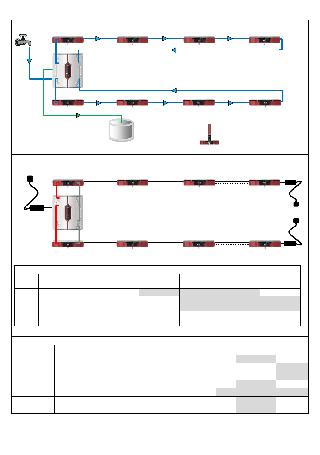
PURELAB Chorus 1 Range with multiple Halo Dispense solutions
Hydraulic / Water Connections
Electrical / Communications Connections
Communication / Power Connection Details
Colour
Description
System 1
Connection
No.
Halo Dispense
1
Connection No.
Halo Dispense
2
Connection No.
Halo Dispense
3
Connection No.
Halo Dispense
4
Connection No.
Black
Power Cable
6 - - - 6
Red
Internal Comm’n Cable
J2
J1 - -
-
Grey
Internal Power Cable
TH4
TH4 - -
-
Black
External Comm’n Cable
Out 9
In 7 – Out 9
In 7 – Out 9
In 7 – Out 9
In - 7
Black
External Power Cable
Out 8
In 6
In 6 – Out 8
In 6
In 6 – Out 8
Parts / Installation Kits Required
Part No.
Description
QTY
Supplied with
System
Ordered
Separately
CEPWGU303754
Power Supply
1
-
✓
LA762
Standard Installation Kit
1
✓
-
LA774
Halo Installation Kit
4 ✓ -
LA777
Integrated Installation Kit
1
-
✓
LA778
Side By Side Installation Kit
- - -
LA779
Remote Installation Kit
3
-
✓
LA575
Pressure Regulator – Fitted when inlet pressure = >0.7bar (10psi)
1
-
✓
Power
Supply
6
J2
Drain
1
Inlet
1
5
1
5
1
5
4
5
3
Note: Drain connection 3 is
required for Life Science and
Analytical Research variants
J2
TH4
J1
TH4
J1
TH4
Note: Halo Flexible Dispense
will not integrate underneath
Drain connection
3 is required
1 5 1
5
3 x External Communication Cables
2 x Power Cables
7 6 7 6 9
9 8 7 6 9
8
Halo 2
Halo 3
Halo 4
Halo 2
Halo 3
Halo 4
Halo 2
Halo 3
Halo 4
Halo 2
Halo 3
Halo 4
7 7 7
9
9 9 6
8
1
1 5 1
5
5
Power
Supply
Power
Supply
6
8
6
27
Page 28
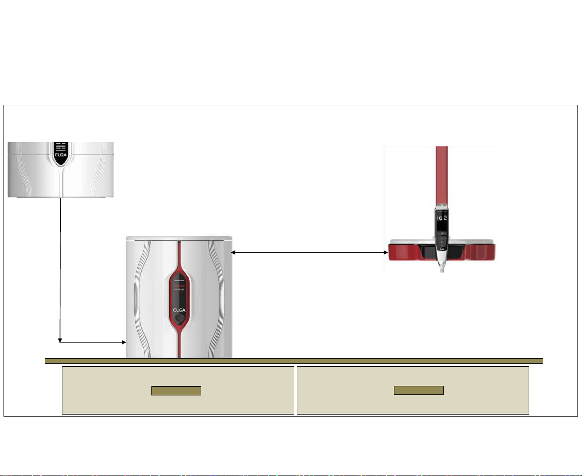
11. GRAVITY FEED - HALO DISPENSE CONFIGURATIONS
1 x Halo Dispense (mounted remotely)
Max Distance 0.0m (00.0’)
Max Flow Rate
0.0 l/min
Dispense
Gravity Geed from
Storage Reservoir
(Flooded Suction)
Page 29
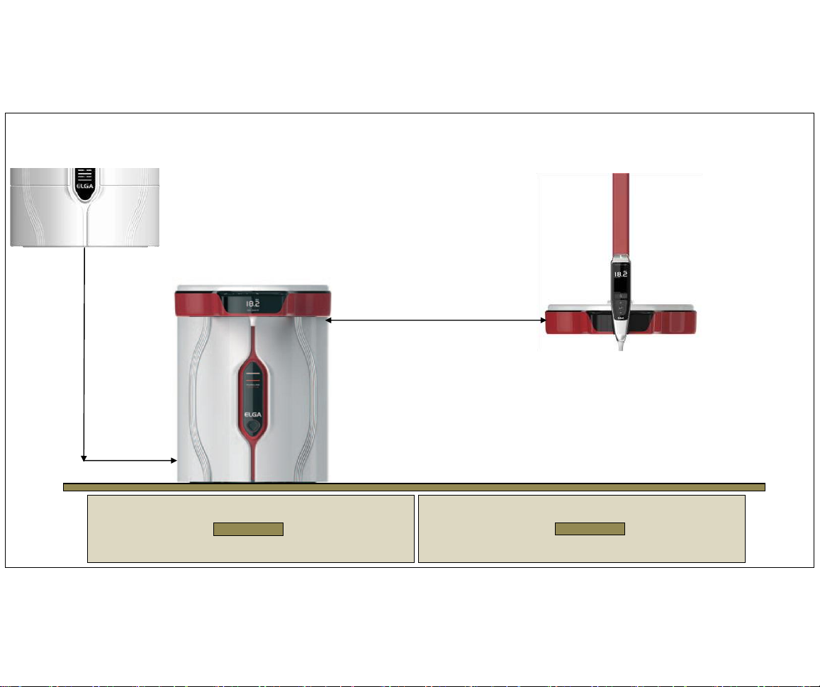
29
2 x Halo Dispensers (1 x integrated & 1 x mounted remotely)
Max Distance 0.0m (00.0’)
Max Flow Rate
0.0 l/min
Dispense
Loop pressure in recirculation
0.0 bar (0.0psi)
Max Flow Rate
0.0 l/min
Dispense
Gravity Geed from
Storage Reservoir
(Flooded Suction)
Page 30
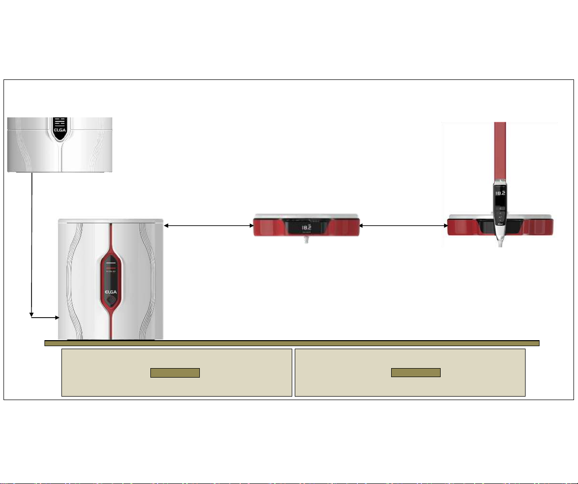
30
2 Halo Dispensers (mounted remotely)
Max Distance
0.0m (00.0’)
Max Flow Rate
0.0 l/min
Dispense
Loop pressure in recirculation 0.0 bar (00.0psi)
Max Flow Rate
0.0 l/min
Dispense
Max Distance
0.0m (00.0’)
Gravity Geed from
Storage Reservoir
(Flooded Suction)
Page 31
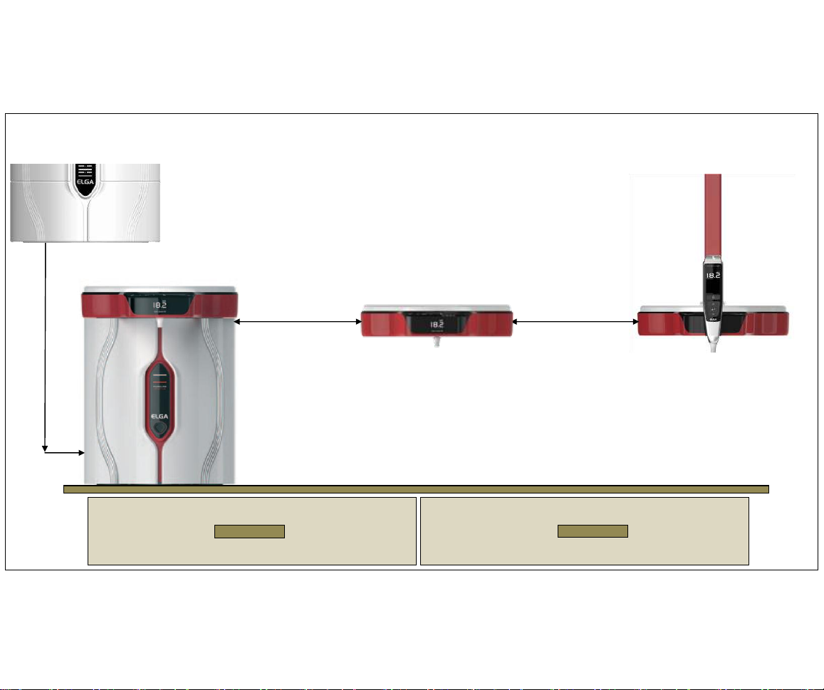
31
3 Halo Dispensers (1 x integrated & 2 x mounted remotely)
Max Distance
0.0m (00.0’)
Max Flow Rate
0.0 l/min
Dispense
Loop pressure in recirculation 1.0 bar (14.7psi)
Max Flow Rate
0.0 l/min
Dispense
Max Distance
0.0m (00.0’)
Max Flow Rate
0.0 l/min Dispense
Gravity Geed from
Storage Reservoir
(Flooded Suction)
Page 32
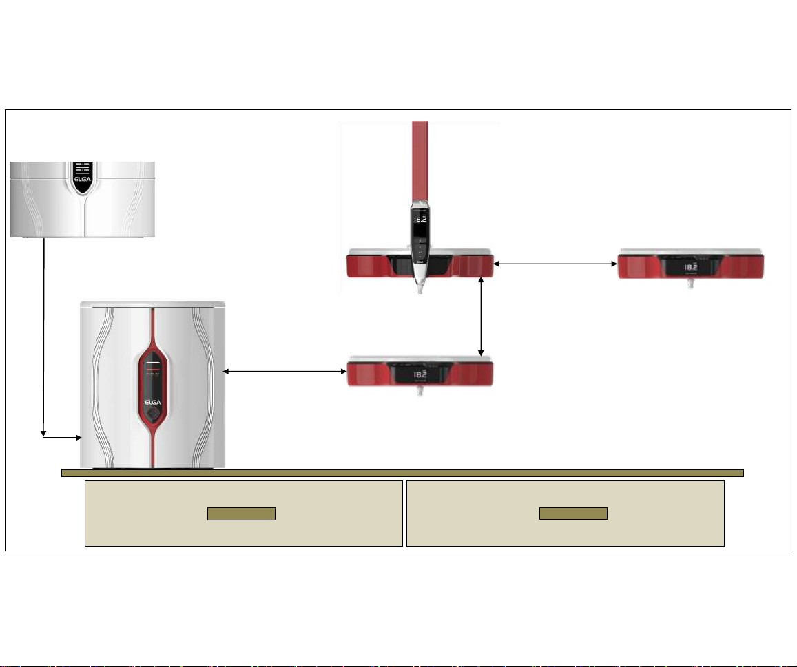
32
3 Halo Dispensers (mounted remotely)
Max Distance
0.0m (00.0’)
Max Flow Rate
0.0 l/min
Dispense
Max Flow Rate
0.0 l/min
Dispense
Max Distance
0.0m (00.0’)
Max Flow Rate
0.0 l/min
Dispense
Max Distance
0.0m (00.0’)
Loop pressure in recirculation 0.0 bar (00.0psi)
Gravity Geed from
Storage Reservoir
(Flooded Suction)
Page 33
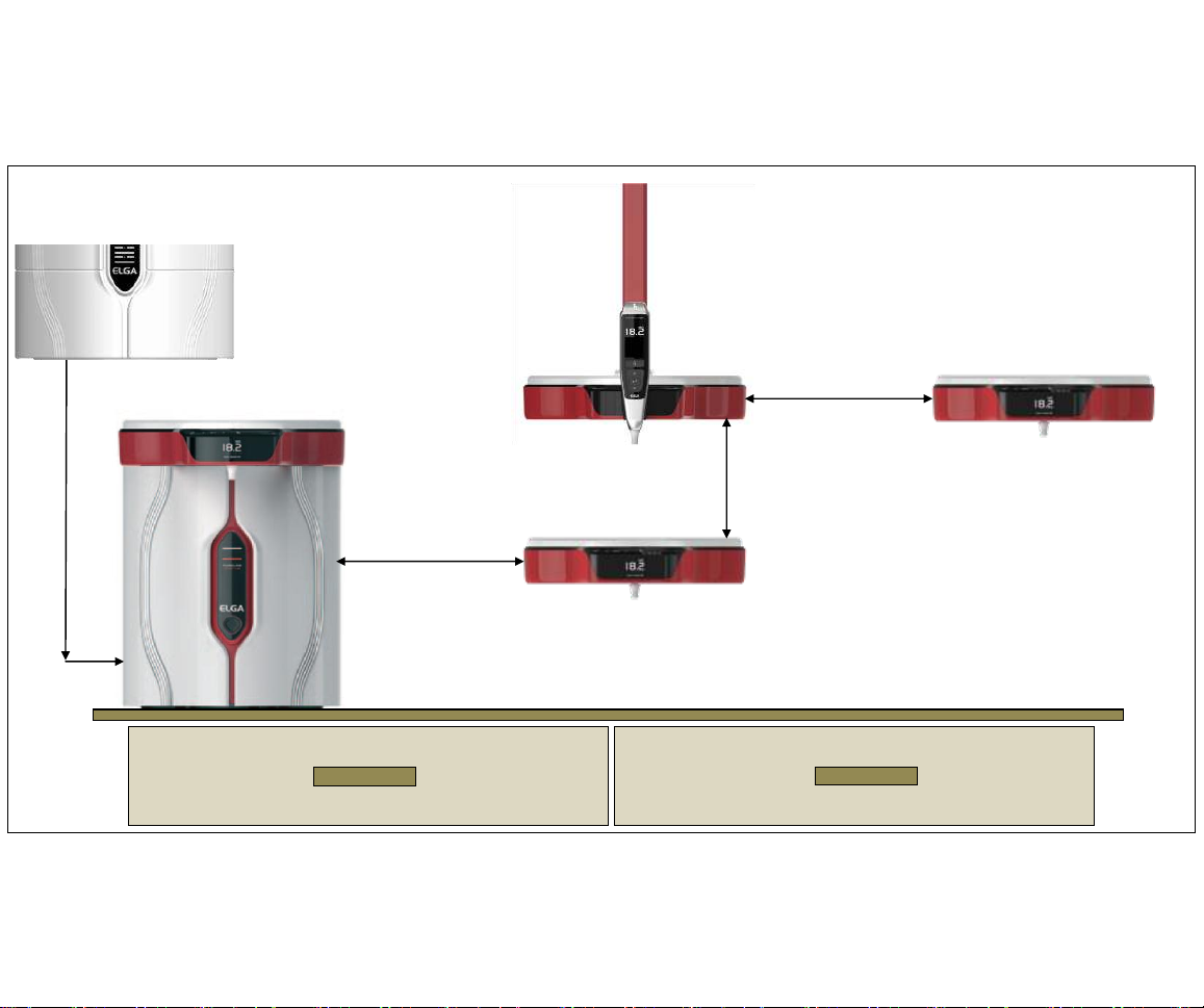
33
4 x Halo Dispensers (1 x integrated & 3 x mounted remotely)
Max Distance
0.0m (00.0’)
Max Flow Rate
0.0 l/min
Dispense
Max Flow Rate
0.0 l/min
Dispense
Max Distance
0.0m (00.0’)
Max Flow Rate
0.0 l/min
Dispense
Max Distance
0.0m (00.0’)
Loop pressure in recirculation 0.0 bar (00.0psi)
Max Flow Rate
0.0 l/min Dispense
Gravity Geed from
Storage Reservoir
(Flooded Suction)
Page 34
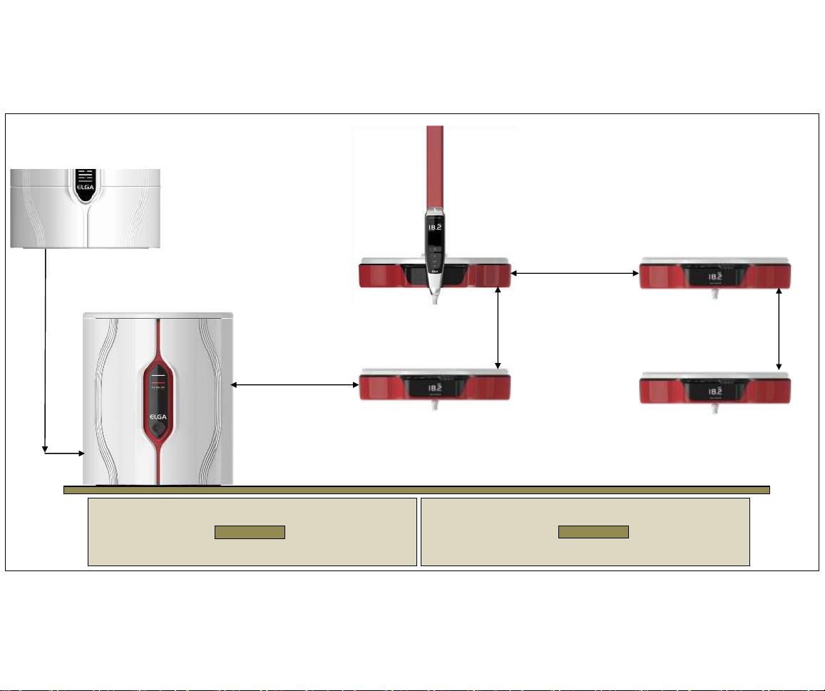
34
4 x Halo Dispensers (mounted remotely)
Max Distance
0.0m (00.0’)
Max Flow Rate
0.0 l/min
Dispense
Max Flow Rate
0.0 l/min
Dispense
Max Distance
0.0m (00.0’)
Max Flow Rate
0.0 l/min
Dispense
Max Distance
0.0m (00.0’)
Loop pressure in recirculation 0.0 bar (00.0psi)
Max Flow Rate
0.0 l/min
Dispense
Gravity Geed from
Storage Reservoir
(Flooded Suction)
Page 35
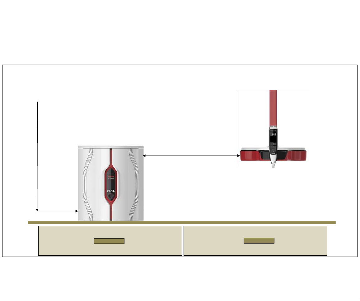
35
12. PRESSURIZED FEED - HALO DISPENSE CONFIGURATIONS
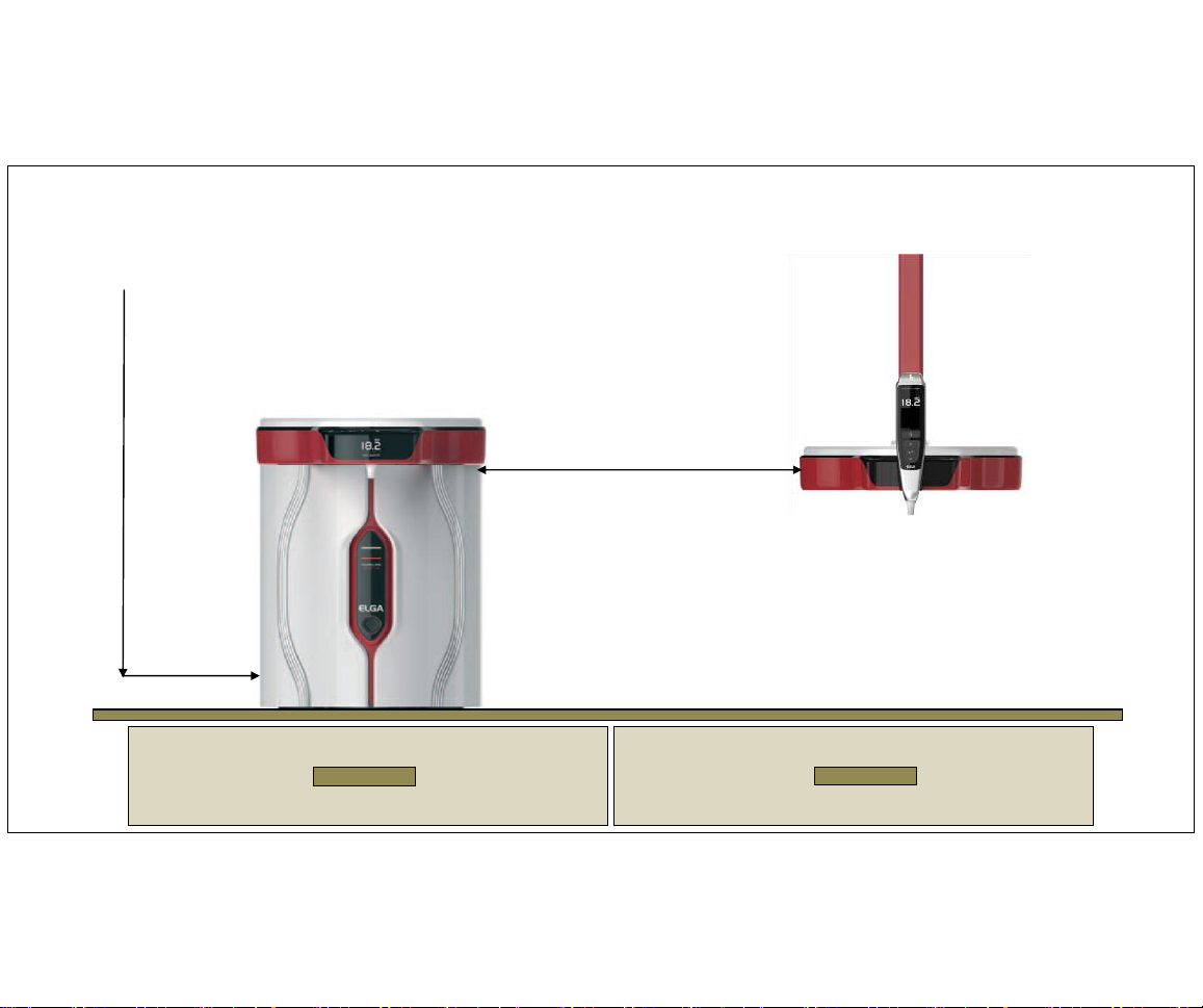
1 x Halo Dispense (mounted remotely)
Max Distance 5.0m (16.0’)
Max Flow Rate
2.0 l/min
Dispense
Inlet Pressure between
1.0bar (14.7psi) and
2.0bar (29.0psi)
(Recommended 1.0 bar)
Page 36
36
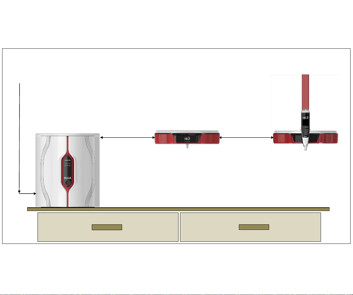
2 x Halo Dispensers (1 x integrated & 1 x mounted remotely)
Max Distance 5.0m (16.0’)
Max Flow Rate
2.0 l/min
Dispense
Inlet Pressure between
1.0bar (14.7psi) and
2.0bar (29.0psi)
(Recommended 1.0 bar)
Loop pressure in recirculation
1.0 bar (14.7psi)
Max Flow Rate
2.0 l/min
Dispense
Page 37
37
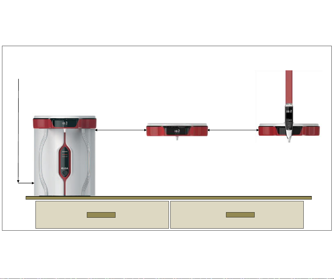
2 Halo Dispensers (mounted remotely)
Max Distance
5.0m (16.0’)
Max Flow Rate
2.0 l/min
Dispense
Inlet Pressure between
1.0bar (14.7psi) and
2.0bar (29.0psi)
(Recommended 1.0 bar)
Loop pressure in recirculation 1.0 bar (14.7psi)
Max Flow Rate
2.0 l/min
Dispense
Max Distance
5.0m (16.0’)
Page 38
38
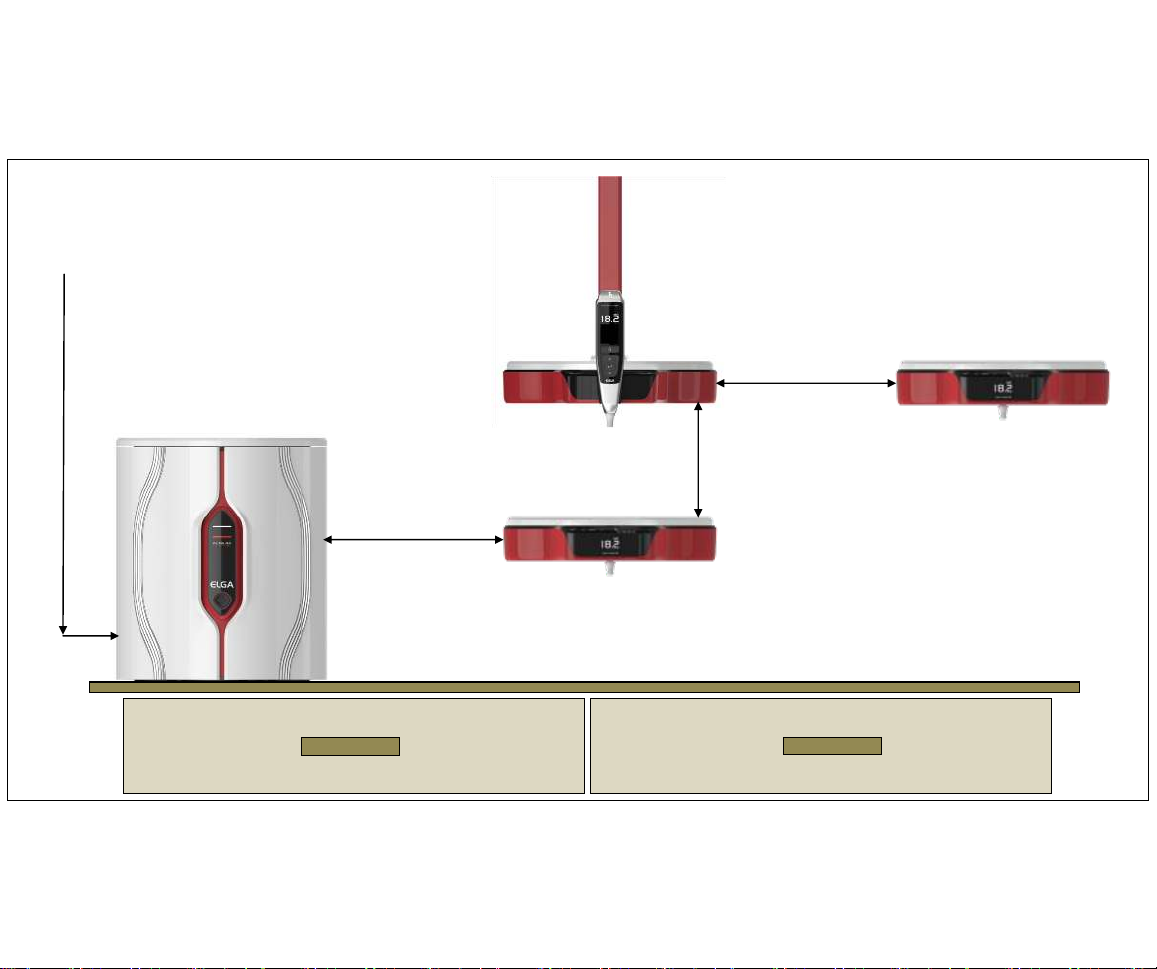
3 Halo Dispensers (1 x integrated & 2 x mounted remotely)
Max Distance
3.0m (10.0’)
Max Flow Rate
1.7 l/min
Dispense
Inlet Pressure between
1.0bar (14.7psi) and
2.0bar (29.0psi)
(Recommended 1.0 bar)
Loop pressure in recirculation 1.0 bar (14.7psi)
Max Flow Rate
2.0 l/min
Dispense
Max Distance
3.0m (10.0’)
Max Flow Rate
2.0 l/min
Dispense
Page 39
39
3 Halo Dispensers (mounted remotely)
Max Distance
3.0m (10.0’)
Max Flow Rate
2.0 l/min
Dispense
Inlet Pressure between
1.0bar (14.7psi) and
2.0bar (29.0psi)
(Recommended 1.0 bar)
Max Flow Rate
2.0 l/min
Dispense
Max Distance
3.0m (10.0’)
Max Flow Rate
1.7 l/min
Dispense
Max Distance
3.0m (10.0’)
Loop pressure in recirculation 1.0 bar (14.7psi)
Page 40
40
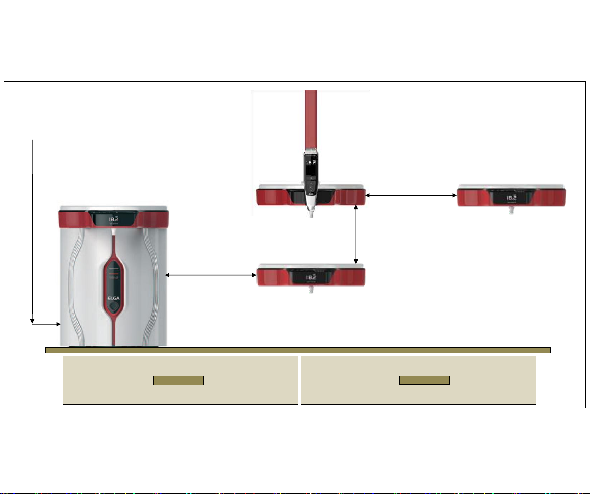
4 x Halo Dispensers (1 x integrated & 3 x mounted remotely)
Max Distance
3.0m (10.0’)
Max Flow Rate
1.7 l/min
Dispense
Inlet Pressure between
1.0bar (14.7psi) and
2.0bar (29.0psi)
(Recommended 1.0 bar)
Max Flow Rate
2.0 l/min
Dispense
Max Distance
3.0m (10.0’)
Max Flow Rate
1.5 l/min
Dispense
Max Distance
3.0m (10.0’)
Loop pressure in recirculation 1.0 bar (14.7psi)
Max Flow Rate
2.0 l/min
Dispense
Page 41
41
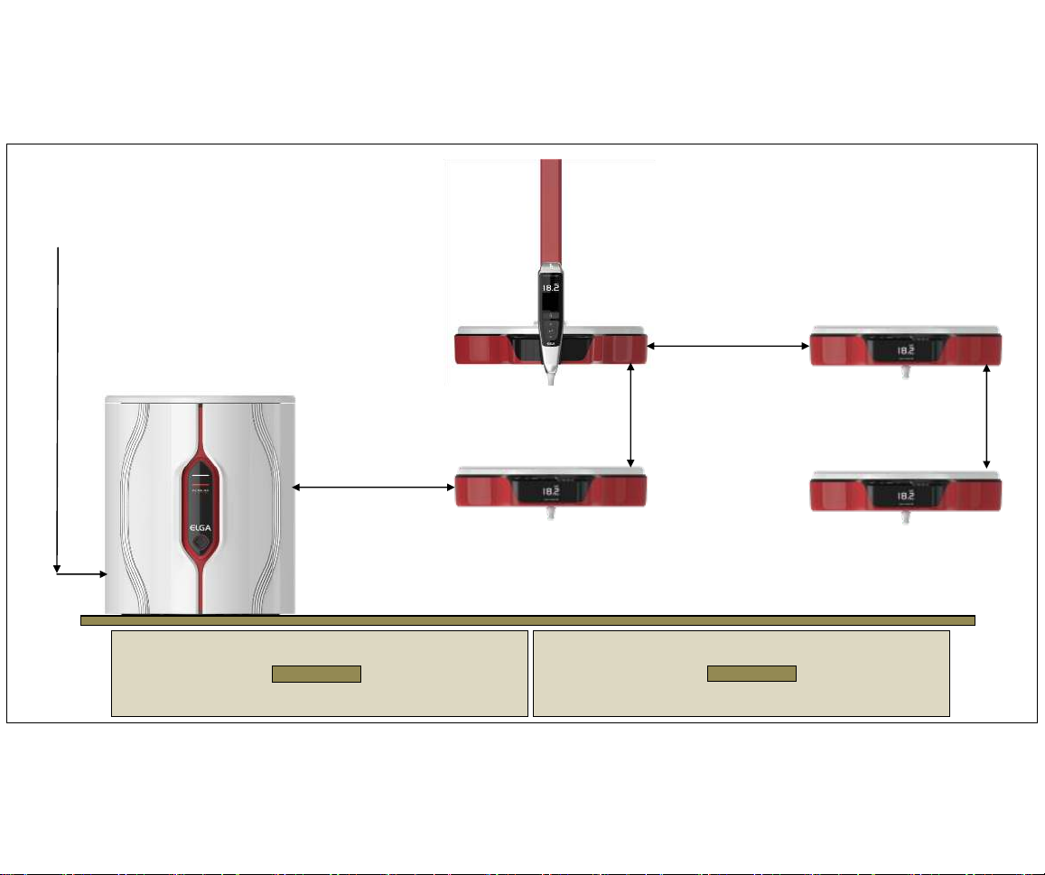
4 x Halo Dispensers (mounted remotely)
Max Distance
3.0m (10.0’)
Max Flow Rate
2.0 l/min
Dispense
Inlet Pressure between
1.0bar (14.7psi) and
2.0bar (29.0psi)
(Recommended 1.0 bar)
Max Flow Rate
2.0 l/min
Dispense
Max Distance
3.0m (10.0’)
Max Flow Rate
1.7 l/min
Dispense
Max Distance
3.0m (10.0’)
Loop pressure in recirculation 1.0 bar (14.7psi)
Max Flow Rate
1.5 l/min
Dispense
Page 42

42
Technical Support
ELGA LabWater Global Operations
DDI: +44 (0)1494 887850
email:
Web:
www.elgalabwater.com
 Loading...