

Elfnet D311-180A, D311-180B, D312-180A, D312-180B, D311-280A Installation Instructions Manual
...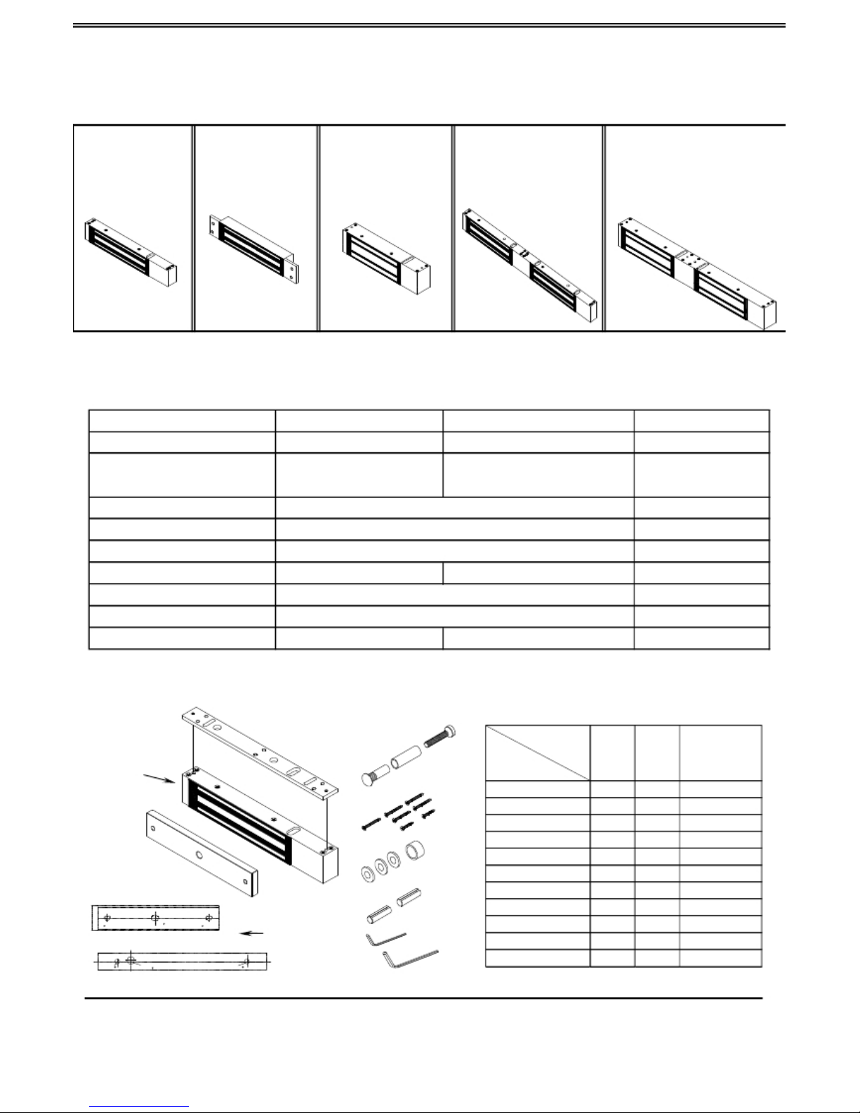
ELECTROMAGNETIC LOCK
INSTALLATION INSTRUCTIONS
-180A/B D312-180A/B
-280A/B D312-280A/B
D311-280A/B
D313-180A/B
D313-280A/B
D313-560B
ation current
DC 12V /DC 24V
400mA/12VDC
200mA/24VDC
500mA/12VDC
250mA/24VDC
NO
0Sec./3Sec./5Sec./9 Sec.
Out-swing door and In-swing door
180Kg/280Kg/560Kg)
35℃ ± 5℃ (Iinside air temperature 30℃)
The warranty is 2 years for normal using
2kg/5kg
Accessories:
Model type
Body
Type
Quantity
Notations
Sexnut Bolt
Door spacer
Screw 4X25mm
Screw 4X15mm
Screw 5X32mm
Screw 5X25mm
Rubber washer
1
1
6
3
4
2
2
A rm a tu re(M i n i)
Washer
3
6.4m m x 12 .5 m m
(1 /4 " x 1/2")
Magnet(Mini)
8 .0 m m
( 5/16 ")
6.4 m m x 1 2.5m m
(1 /4" x 1/2")
Alignment
sticker
Allen
keys
3mm
Hexgon keys
5
mm
Guide pins
1
1
2
3.2mm(1/8")
8mm(5/16")
3.2mm(1/8" )
Page 1
Installation instructions :
When installing magnetic lock user should be sure of the type of door used .Magnetic
lock is specifically for the use of out-swing door.A bracket is used to install with
magnetic door for in-swing door.
Armature
Armature
Screw
“Z” Bracket
“L” Bracket
Indoor
“L” Bracket
Door
Frame
Outdoor
Door leaf
[Out-swing door]
[In-swing door] [“L.Z.” Bracket]
[Installation ]
Step1 :
Place the magnet template on top of door frame and the armature template on top of door
leaf according to the above drawings . Try to check if they are on the right position before
drilling all the holes.
Step2 :
Fix the mounting plate in the door jamb using
supplied self-tapping screw.
Mounting plate
( Smooth surface faces up )
Step3 :
Ensure the armature is set to the right position and drill a 12 mm hole from sexnut
bolt side and drill an 8 mm hole through the door .When hollow door is used , user
should drill a 16 mm hole . A door spacer is used to fit in a sexnut bolt. Then,push
the sexnut bolt in the drilled hole and tighten it with screw driver . The armature
must be loose slightly to compensate the door misalignment , so that the armature
face and the magnet face can be closed and make the magnetic force to maximum
effect.
Rubber washer
Rubber washer
Armature Screw M8
Door leaf
Knock guide
pins in to
Drill 12 mm (1/2”) Ø X
fasten the
25mm (1”) from sexnut
Drill an 8mm (5/16”)
armature
[1]
hole through door
[2]
must be loose
slightly
Page 2

ON
1 2
主體固定板
lock
Step 4: Select the correct voltage and delay time
※ Voltage Selection Jumper
Body
+V
Power Input
—V
+V
Power I nput
—V
Armature
COM
N. O.
N. C.
N. O.
COM
N. C.
Primary Standard
Time Delay Switch
Blade Stop
Door
0.0sec
5.0sec
2.5sec
9.0sec
S2
Power
Supply
V+
V-
P.S
0.0 SEC
2.5 SEC
Mounting Plate
Exit
Bu tton
N.O
5.0 SEC
9.0 SEC
Voltag e Selec t
12V 24V
COM .
N.C
1
2
ON
Monitor Output
Autolock Delay
Time Settings
Armature
※Monitor output (0.5A) will change to N.O. point when
magnetic lock and armature are engaged (Red light of indicator
Rubber Washer
will change to green light )
Door leaf
[Installation diagram]
Step 5 :
Fix the magnet to the mounting (screws for fitting are included in the magnetic body)
and ensure the armature close lightly against the magnet when the door is closed to
avoid damage to the mating surface unnecessary.
-swing door] (Bracket shall be used to install)
Step 1 :
Fix the magnet in the door jamb and fix the armature with the L.Z. bracket in the
door leaf. (as follow)
Outdoor
Indoor
※ ( Setting of voltage, please refer to out-swing door 『 Step 4 』)
Page 3

Armature
Armature
Screw
“Z” Bracket
“L” Bracket
“L” Bracket
Door
Frame
Outdoor
Door leaf
Outdoor
Pull
Indoor
Indoor
[Installation diagram for bracket and magnetic lock]
Attentions:
(1) Regardless the type of door used, the lock must be installed or mounted indoors.
(2) The armature must be loose slightly to compensate the door misalignment.
(3) Door spacer is used to prevent any damage to the hollow door when it is tightened.
(4) One series of armature brackets are used when installing out-swing.
wooden
door
wooden
door
To be used with
bracket
glass
door
Armature plate housing
Armature plate bracket
Glass holder
Question & answer
Door is not lightly locked?
1.Check if the voltage is correct2.Check if the setting of voltage is correct3.Check if the magnetic lock and armature are engaged lightly.
Indicator light is unable to show green light when door closed?
1.Check if the armature is mounted to the correct position.
2.Check if the voltage is set correctly. Any dust or rust will affect the operation of the lock.
Maintenance of the magnetic lock?
1.Any dust or rust should be removed regularly.
2.Lubricant should be apply on the magnetic lock to avoid any rust depending on the environment it is installed (such as seaside).
Page 4
 Loading...