

Page 1
Digital Surveillance Recorder
Installation Guide
Page 2

Contents
CONTENTS .................................................................................................................................................. 2
HOW TO USE THIS MANUAL ................................................................................................................. 4
SECTION 1..DIGITAL SURVEILLANCE RECORDER OEM INSTALLATION GUIDE................ 5
UCL UCC4 QUICK INSTALLATION............................................................................................................ 5
INSTALLATION GUIDE FOR DSR PACKAGE................................................................................................. 6
SOFTWARE INSTALLATION ......................................................................................................................... 9
OPERATION ................................................................................................................................................ 9
SECTION 2 UPGRADING VIDEO DISPLAY BOARD FOR TV OUT FEATURE ......................... 10
UPDATING VIDEO DISPLAY BOARD (FOR TV OUT):................................................................................. 10
REMOVE THE ORIGINAL VIDEO BOARD ..................................................................................................... 10
INSTALL THE NEW VIDEO BOARD.............................................................................................................. 10
ACTIVATE THE TV MONITOR ................................................................................................................... 10
SECTION 3 SYSTEM SET UP FOR DSR INTELLIGENT REMOTE PLAYER ............................. 11
SYSTEM CONFIGURATION PROCEDURE FOR DSR INTELLIGENT REMOTE PLAYER VER.2.0....................... 11
SECTION 4 DSR DIAL-UP SERVER SETTING.................................................................................. 13
DIAL-UP SERVER TCP/IP SETTING FOR WINDOWS 98.............................................................................. 13
SECTION 5 INSTALLATION INSTRUCTION FOR OPTIONAL VIDEO COMPRESSION
CODEC (S).................................................................................................................................................. 15
INSTALLATION INSTRUCTION FOR OPTIONAL VIDEO COMPRESSION CODEC............................................. 15
INSTALLATION OF MJPEG CODEC TO WINDOWS 95/98 ........................................................................... 15
INSTALL MPEG4 ON WINDOWS 95/98 ..................................................................................................... 16
SECTION 6 INSTALLATION OF ALARM I/O COMPONENTS ...................................................... 17
INSTALLATION OF ALARM I/O HARDNESS ................................................................................................ 17
TYPICAL CONFIGURATION ............................................................................................................... 18
ALARM INPUT CONNECTION............................................................................................................ 19
COLOR CODE OF ALARM INPUT AND OUTPUT CABLES............................................................. 20
SECTION 7 INSTALLATION OF WINDOWS 98 OS ......................................................................... 21
INSTALLATION OF WINDOWS98 SE TO A NEW PC SYSTEM FOR DSR........................................................ 21
NEW INSTALLATION USING THE CD-ROM VERSION OF WINDOWS 98...................................................... 21
LOGGING ON TO WINDOWS 98 ................................................................................................................. 24
SECTION 8 INSTALLATION OF OPTIONAL PC PERIPHERAL ADD-ON’S .............................. 25
SECTION 9 INSTALLATION OF APPLICATIONS SOFTWARE ................................................... 26
INSTALLATION OF DSR APPLICATION SOFTWARE.................................................................................... 26
APPENDIX I STORAGE CAPACITY CALCULATION .................................................................... 27
A COMMON QUESTION ABOUT THE STORAGE CAPACITY ........................................................................... 27
THE RECORDING CAPACITY OF DSR ......................................................................................................... 27
APPENDIX II CAMERA INFO STORED IN THE REGISTRY......................................................... 29
CAMERA INFORMATION STORED IN THE REGISTRY .................................................................................. 29
APPENDIX III COMPACTING DATABASE FOR DSR..................................................................... 30
www.elfinx.com TX-DSR04 Installation Guide Page 2 of 32
Page 3

COMPACTING DATABASE FOR DSR.......................................................................................................... 30
SYSTEM MAINTENANCE ................................................................................................................... 30
APPENDIX IV DSR PACKAGE SPECIFICATION............................................................................. 31
DSR-416 PACKAGE.................................................................................................................................. 31
www.elfinx.com TX-DSR04 Installation Guide Page 3 of 32
Page 4

How to use this Manual
Whether you’re already familiar with or new to our DSR Digital Video Surveillance
Recorder, you my find useful information in this Installation Manual to properly
configure the DSR system which is PC based system with implemented on top of the
Microsoft Windows 98 SE OS.
If you are configuring the system Read
From a DSR package model and a new PC
system
Upgrade of an existing DSR System Section 1, Quick installation Guide
For remote Access, Viewing and
Recording
Upgrading for TV Out Feature Section 2, Upgrading Video Display Board
Upgrading the system with optional Video
Compression Codec
Section 1, Quick installation Guide
Section 7, Windows 98 OS Installation
Section 8, Installation of Add on board
Section 9, Installation of Applications
Software
Other applicable section compatible with
the package acquired
Section 8, Installation of optional Add-on
board (s)
Section 9, Installation of Applications
Software
Other applicable section compatible with
the package acquired
Section 3, Set up for Intelligent Remote
Player
Section 4, Set up for Dial-Up Server /
Client
for TV Out Feature
Section 5, Set up for optional Video
Compression Codec (s)
www.elfinx.com TX-DSR04 Installation Guide Page 4 of 32
Page 5

Section 1 DIGITAL SURVEILLANCE RECORDER OEM Installation Guide
Section 1..DIGITAL SURVEILLANCE RECORDER OEM
Installation Guide
UCL UCC4 Quick Installation
Installing Hardware:
1. Power off your PC and open the case.
2. Remove the screw and coverplate of an unused expansion PCI slot.
3. Press the UCC4 Video Capture Card firmly into the slot.
4. If you have more than one UCC4 card in your DSR product package, Repeat the
above steps until all the boards are inserted.
5. Please use the nuts provided to fasten the UCC4 cards from the rear end of your PC.
6. Close the case of your PC.
7. You are now ready to connect your video source to the capture card(s), please ensure
all connection are secured.
8. The hardware Installation is completed.
Installing the Software:
Notes: If you have an existing video captures device in the system, make sure to remove
the drivers before physically removing the device.
1. Turn on your PC and starts Windows 95/98.
2. Shortly after entering Windows system a dialog box with a message of “Add New
Hardware Wizard” is shown and follows a window with the “UCC Video Capture
Device” appears on your screen. Click ‘NEXT” twice.
3. Insert the UCC Video Capture Device setup diskette into drive A.
4. Click the “NEXT” button. This will bring up the screen showing UCC Video Capture
Device.
5. Click the “NEXT” button to install the driver. This will bring up the Copying
Files…..in progress screen.
6. After all the driver files are copied, the System Setting Change screen appears.
7. Repeat the above procedure until all the video and audio drivers are copied to the
system
8. Now… you are ready to install the DSR application.
9. Insert “DSR Application CD” into the CD-ROM drive. The autorun will take place
immediately and a window of “DSR Application” menu will be shown on your
screen.
10. Select and click the Model and Options from the list and Click the “NEXT” button.
Follow all the procedures outlined on the screen to finish installing the application
software.
More detail about installation and software version, please refer to the readme.txt file
located in the CD by selecting the “Exit Installation” first.
www.elfinx.com TX-DSR04 Installation Guide Page 5 of 32
Page 6
Section 1 DIGITAL SURVEILLANCE RECORDER OEM Installation Guide
Alarm
PCI bus
1
2
3
4
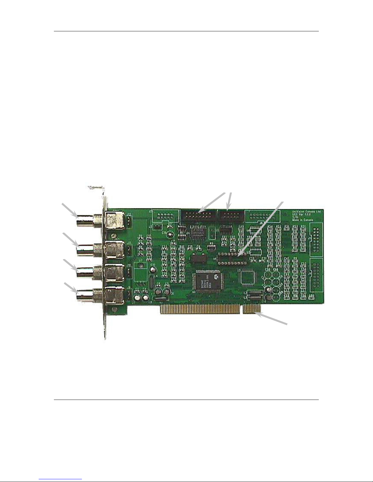
Installation Guide for DSR Package
DSR Digital Surveillance Recorder Package consists of the following items:
• Four UCC4 cards (one of the four card consist of a security control key installed in
the IC socket)
• Lock nuts for BNC connectors
• Ribbon cable harness for alarm I/O connection (with DB25 and DB15 female
connectors to PCB connectors)
• Alarm I/O cables (with DB25 and DB15 male connectors)
• DSR software installation disk (CD-ROM/Floppy disks)
• DSR User Manual
Video in
Video in
Video in
Video in
Security Key IC
UCC4 Video Capture
Card
www.elfinx.com TX-DSR04 Installation Guide Page 6 of 32
Page 7
Section 1 DIGITAL SURVEILLANCE RECORDER OEM Installation Guide
Camera
9
10
11
12
5
6
7
8
1
2
3
4
13
14
15
16
Screw
Hardware Installation
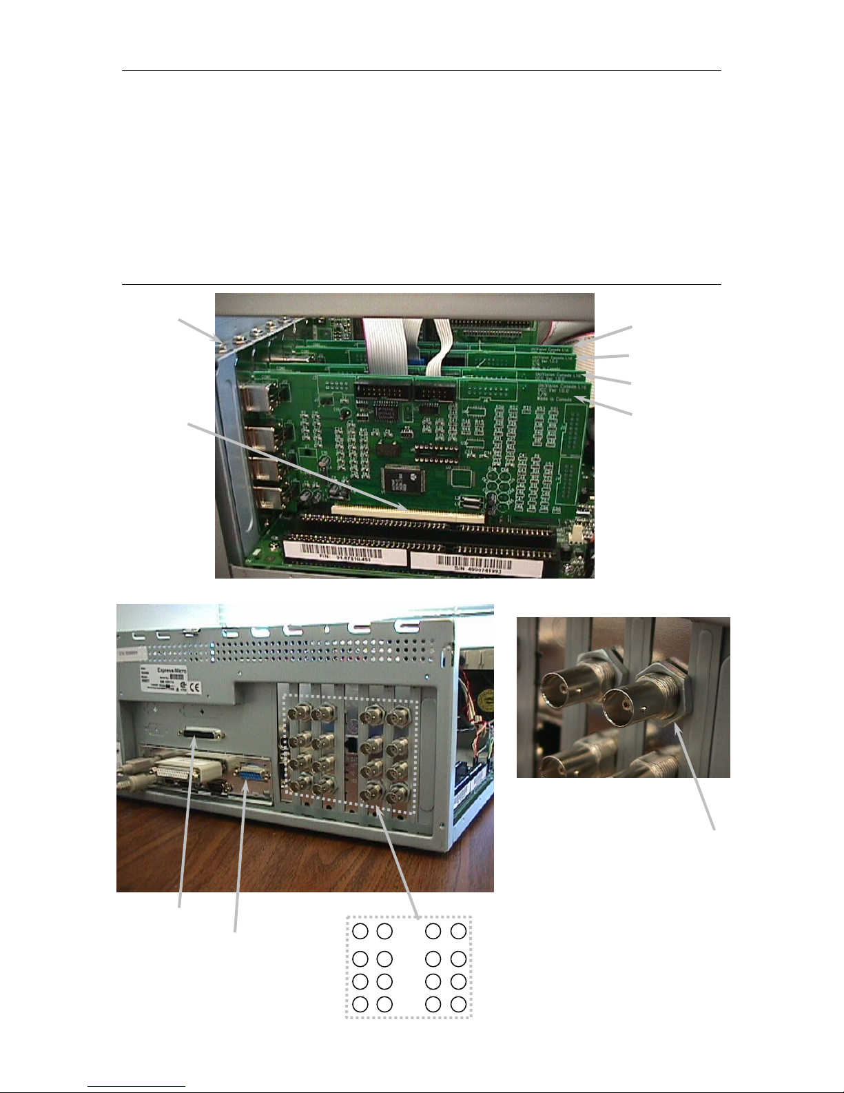
Step 1 – Install the UCC4 cards
• Turn off the computer, and remove the cover.
• Locate four available PCI slots in your computer, and firmly insert individual UCC4 cards
into the PCI slots. (See figure 1)
• Secure the cards with retaining screws. (See figure 1)
• Put a nut (provided) into each BNC socket from the rear panel of the PC and tighten. (See
figure 2)
Retain
UCC4 #3
UCC4 #2
UCC4 #1
PCI slot
UCC4 #4
Figure 1
Alarm connector #1
Alarm connector #2
www.elfinx.com TX-DSR04 Installation Guide Page 7 of 32
Figure 2
Lock Nut
Page 8

Section 1 DIGITAL SURVEILLANCE RECORDER OEM Installation Guide
Red mark
#2
UCC4 #4
UCC4 #1
UCC4 #2
UCC4 #3
UCC4
card
Camera
inputs
Card #1 1, 2, 3, 4
Card #2 5, 6, 7, 8
Card #3 9, 10, 11, 12
Card #4 13, 14, 15,
16
Note: The actual no. and
position of UCC card and
that of the cameras will vary
with different Mother Board
used, case shown as per
AOPEN AX6BC mother
board only
Step 2 - Install the alarm I/O ports
• Locate pre-cut connector openings for the DB25 and DB15 alarm connector at the rear panel.
• Secure the alarm connectors to the opening. (See figure 3 and 4)
• Connect the other end of the ribbon cable to the UCC4 cards as shown in Figure 4.
• Restore the cover on your PC.
Alarm connector
Alarm connector #2
(DB25)
Ferrite
Figure 4
UCC4#4
UCC4#1
LAN Card
Ribbon cable
UCC4 #2
UCC4 #3
www.elfinx.com TX-DSR04 Installation Guide Page 8 of 32
Page 9

Section 1 DIGITAL SURVEILLANCE RECORDER OEM Installation Guide
Software Installation
Step 1 – Prepare and format the system drives
• Format the hard drive and transfer the DOS into it.
• Install the CD-ROM driver software into the computer so that you can access the CD-ROM.
• Install Windows 98 into the PC, see section 7 for details
• If necessary, Install the driver for following peripheral adapter(s), see section 8 of this
manual for details:
♦ Network card driver
♦ Modem driver
♦ Sound card driver
♦ Printer driver.
• If necessary, Install the IE5.0 into the PC.
• Put the provided DSR installation software CD-ROM disk into the CD-ROM drive and
Run the Setup program in the disk.
•
Operation
For operation instruction, please see DSR User Manual.
www.elfinx.com TX-DSR04 Installation Guide Page 9 of 32
Page 10

Section 2 Upgrading Video Display Board for TV Out Feature
Section 2 Upgrading Video Display Board for TV Out Feature
Updating Video Display Board (For TV Out):
From time to time, there is the need to update the Video Display Board of the PC Main processing Unit, the
system for various reasons, such as to provide a secondary Video Out (to VGA Monitor or a TV Monitor).
For the latter, you may need the original video board on the system, the ATI LT Rage Pro to be replaced
with the ATI Rage Pro Turbo video board, hereby called the new one. The following procedure is used to
update the video board:
Remove the original video board
1. You must first remove the original video board driver:
2. Open the Control Panel by clicking on Start/Settings/Control Panel.
3. Now pop the System properties setup by double clicking on its icon.
4. Click on the Device Manager folder.
5. Double click on Display adapters, then the ATI LT Rage Pro
6. Click on the Remove button.
7. Shut Down the computer
8. Remove the original video board from the system.
Install the new video board
1. Insert the new video board into the system, tight up the screw. Replace the system covers.
2. Turn on the system, when a dialog box with “Add New Hardware wizard” appears, click Cancel
3. When the system boots up to Windows98, put the Installation CD which comes with the video board
into the CR-ROM drive. Autorun process will start shortly.
4. Select express Install option from the Displayed Menu, then follow the pop up instructions to
complete the remaining processing step.
5. Shut Down and Re-start the system to effect the change.
Activate the TV Monitor
1. Connect the composite video out signal from the RCA jack of the new video board to the video in of
the TV Monitor, which has a standard input impedance of 75 ohm.
2. Open the Control Panel by clicking on Start/Settings/Control Panel
3. Now pop the Display properties setup by double clicking on its icon
4. Click on the Setting tab, and then click the Advanced.. button, a setting Menu will appear.
5. Click the Display tab, Check on the TV display as it is enable for selection. (If the TV Monitor
selection box is not enabled, you have to check that all the connection are properly set up, restart the
computer system and ensure the display driver function properly). The display resolution and rate of
refreshment will be automatically adjusted to fit the standard TV signal.
6. If the display on the TV screen shows at the system boot up but there is no display on the TV Monitor
after booting into the Windows 98, Adjust the Display resolution to 800 x 600 with 16 bit color. And
restart the system.
7. If both the VGA and TV Monitor display are selected. The Displayed height on the VGA Monitor will
be changed you may need to adjust (enlarge) the height of the display using the scale button control of
the VGA Monitor. This is due to the fact the sweeping signal of both displays has to be synchronized
to that of the standard TV signal
Note: If you have problem identifying the type of ATI video board you are handling, before and
after the installation process, you can simply insert the Installation CD into the system drive and
Select Adapter Information from the Menu. The type of video board will be displayed.
www.elfinx.com TX-DSR04 Installation Guide Page 10 of 32
Page 11

Section 3 System Set up for DSR Intelligent Remote Player
Section 3 System Set up for DSR Intelligent Remote Player
System configuration Procedure for DSR Intelligent Remote
Player ver. 2.0
Before installing the setup program for DSR Intelligent Remote Player, the PC is required
to be setup as follows:
1. Install Modem (if dial-up access mode is required)
Make sure a modem is correctly installed.
2. Install PCI Ethernet Card (if LAN access mode is required, i.e. the PC is within the
same LAN of the DSR station(s))
Make sure a PCI Ethernet card is correctly installed.
3. Setup the Network
Locate:
My computer, open Control panel, open Network, inside Configuration tab
Make sure the following items have been installed in the configuration:
For dial-up connection For LAN connection
- Client for Microsoft
Networks
- Dial-Up Adapter - PCI Ethernet Adapter
- NetBEUI->Dial-Up Adapter
- TCP/IP->Dial-Up Adapter - TCP/IP->PCI Ethernet Adapter
Locate:
My computer, open Control panel, open Network, inside Identification tab
Make sure to have the following input:
- Computer name: (input your computer name for ID purpose)
- Workgroup: (same name designated by the LAN server for DSR stations)
- Computer Description: (Option)
4. Make a New Dial-up Connection
Locate:
My computer, open Dial-Up Networking, click Connections in menu bar, click Make
New Connection
- Name for the computer you are dialing : (input a name for the remote DSR
station)
- Select a modem: (select the existing modem)
- Area code: (input area code)
- Telephone number: (input the telephone number of the remote DSR station)
- Client for Microsoft Networks
- NetBEUI->PCI Ethernet
Adapter
www.elfinx.com TX-DSR04 Installation Guide Page 11 of 32
Page 12

Section 3 System Set up for DSR Intelligent Remote Player
- Country code: (input country code)
A new icon will be produced with the name for the computer you are dialing (i.e. the name of the
remote DSR station). Right click the new icon, select Properties, select Server Types
- Type of Dial-Up Servers: PPP, Internet, Windows NT Server, Windows 98
- Check the “Log on to network”
- Check the “Enable software compression”
- Check the “NetBEUI”
- Check the “TCP/IP”
Follow on the installation of DSR Intelligent Remote Player setup by Pressing "Start",
Select "Run" and type " A:\setup.exe" Where A is the (Floppy Disk) drive no. of where
you input the DSR Intelligent Remote Player application disk.
www.elfinx.com TX-DSR04 Installation Guide Page 12 of 32
Page 13

Section 4 DSR Dial-Up Server Setting
Section 4 DSR Dial-Up Server setting
Dial-up Server
Install dial-up Server in Windows 98
1. Select “Settings” by clicking “Start” menu, then click “Control Panel”;
2. Double click the “Add/Remove Programs” icon, select “Windows Setup” tag from
the “Add/Remove Programs Properties” dialog box;
3. Highlight the “Communications” option from the “Components” box, then click
“Details”;
4. Make sure the “Dial-up Server” box having been checked, then click “OK”, and
“Apply”;
5. Insert your 98 Setup CD onto your CD-ROM, then click “OK”;
6. Dial-up Server should be installed successfully after files copying is done.
Configure dial-up Server
1. Double “My computer” on your Desktop, then double click the “Dial-up
networking”;
2. Click the “Dial-up Server” from the “Connections” option on the top of menu bar, a
dialog box appears;
3. Check the “Allow caller access” option box, click “Server Type”, a “Server Types”
dialog box appears;
4. Select “PPP: Internet, Windows NT, Windows 98” option from “Type of dial-up
Server” combo box, and uncheck the “Required encrypted password” box , the click
“OK”;
5. Click “Apply”, then “OK”.
Dial-up Server TCP/IP Setting For Windows 98
This installation is applicable to the Remote Viewing station using the DSR Intelligent Remote
Player incorporated with enhanced video resolution, such as for ver. 2.0.3. For remote playing
using telephone line dial-up, the IP address associated with the Dial-up Adapter of the DSR
system should be entered instead of the Computer Name. In case of connection via LAN, either
the computer name or the IP address associated with the Network adapter can be applied.
Before this part of the TCP/IP configuration, the system is required to be properly configured per
Section 3 of this Manual, Setup for DSR Intelligent Remote Player.
TCP/IP Setup for Server (The DSR system for transmission):
1. Select “Settings” by clicking “Start” menu, then click the “Control Panel”;
2. Double click the “Network” Icon, the Network Properties window will appear;
3. Highlight the “TCP/IP->Dial-up Adapter” item, then click “properties”, a “TCP/IP properties
information” message box pops up, click “OK”, a “TCP/IP properties” dialog box will
appear;
www.elfinx.com TX-DSR04 Installation Guide Page 13 of 32
Page 14

Section 4 DSR Dial-Up Server Setting
4. Make sure the “IP Address” Tab is selected;
5. Check the “Specify an IP address” option, enter “192.168.55.1” as an example* to the IP
Address entry, enter “255.255.255.0” to the Subnet Mask entry;
6. Click “OK” twice, a copy file dialog box will appear, you may require to insert the
Windows98 SE Installation CD-ROM for system files update.
7. Restart the computer.
*if you are using an existing network workstation, please consult your network administrator for
the correct setting.
www.elfinx.com TX-DSR04 Installation Guide Page 14 of 32
Page 15

Section 5 Installation Instruction for optional Video Compression Codec
Section 5 Installation Instruction for optional Video
Compression Codec (s)
Installation Instruction for optional Video Compression Codec
Before this part of installation for optional Codec for video compression and decompression,
make sure the corresponding option of the DSR Application Software is installed into the DSR
system. Please refer to Section 9 of this manual, Installation of Application Software (Pack) for
details. The same Codec must also be installed on the PC system, which is used for Remote
Viewing (Using Remote Video Client) or Playback (Using Remote Video Player).
Optional Codec is not included in the DSR Application CD as a standard. It is acquired through
download from receptive web-site or via separate purchase.
Installation of MJPEG Codec to Windows 95/98
A copy of the picvideo2.exe file is required for this installation, you may download the “PIC
Video Motion JPEG software from www.jpg.com web-site.
During this download, you will have to register user name for each download copy of the
software. And you will receive a set of registration numbers for either of the compression and the
decompression modules. The Registration Numbers shown below are for illustration purpose.
Please insert those numbers associated with the files download
1. Double click the "picvideo2.exe".
2. Click "OK" in "Welcome!" dialog box.
3. In "Select Codecs to Install" dialog box, remove checks in "Wavelet” and "Lossless JPEG"
check boxes then click "OK".
4. In "Registration Information" dialog box, type in your registered user name, for example
"peter", in User Name edit control then click "OK".
5. Click "OK" in "Installation Complete!" dialog box.
6. Double click "Multimedia" icon in "Control Panel".
7. In "Multimedia Properties" dialog box, select "Devices" page.
8. Double click "Video Compression Codecs" item.
9. Double click "PICVideo MJPEG Codec" item.
10. In "PICVideo MJPEG Codec Properties" dialog box, click "Settings...".
11. Fill "14337xxxx" in "User Registration Number:" box for decompressor and "13210xxxx" for
compressor then click "OK".
12. Click "OK" in "PICVideo MJPEG Codec Properties" dialog box.
13. Click "OK" in "Multimedia Properties" dialog box.
14. Close "Control Panel".
Example Registration Numbers
user name for decompressor for compressor
peter 14337xxxx 13210xxxx
smith 12511xxxx 11513xxxx
www.elfinx.com TX-DSR04 Installation Guide Page 15 of 32
Page 16

Section 5 Installation Instruction for optional Video Compression Codec
Install MPEG4 on Windows 95/98
A copy of the mpg4c32.dll file is required for this installation; you may download
the “Windows Media Tools” from the Download Center of www.microsoft.com web
site. The MPEG4 codec will be automatically installed together with the Windows
Media Tools. However, if necessary, you need install it manually, please follows
the instruction:
(Assume Windows 95/98 is installed in c:\windows, otherwise, change the folder c:\windows to
the folder where Windows 98 installed)
1. Copy MPG4C32.dll into c:\windows\system.
2. Open system.ini file located in c:\windows with Notepad.exe.
3. Find the section headed by [drivers32]
4. add new lines as follows in this section
Rem vidc.mp43=MPG4C32.dll (This line is not needed for new DSR v1.7 and its
accompanying Intelligent Player or newer application)
vidc.mp42=MPG4C32.dll
5. save and close system.ini file
6. Restart the system
www.elfinx.com TX-DSR04 Installation Guide Page 16 of 32
Page 17

Section 6 Installation of Alarm I/O components
Section 6 Installation of Alarm I/O components
Installation of Alarm I/O hardness
The DSR system or its package product is equipped with a simple and straightforward
alarm I/O interface scheme. Using the camera no. as the key reference, you can trigger
the alarm recording of any camera with a make or break condition on its corresponding
alarm input terminal no. Once the hardness is setup, you may reverse the alarm input
status by checking or un-checking the “NO”, normally open check box from the alarm
setting dialog box. For example if the field of vision of a camera is at the entrance of
door, we may set the alarm condition with the door sensor about the door Open /Close
condition. We can then record all the case when anyone open the door to enter the
surveillance area.
For Alarm output, the system is will provide an Open Collector (TTL logic level) as
output signal, this is adequate to support the triggering circuitry of general purpose alarm
devices. Application specific driver/buffer may be required for integration to other
(external) devices.
Precaution has to be made in the proper design and installation of alarm output and input
circuit to avoid possible electrical surge or back-drag of electrical current as the PC-based
system is a delicate system its system stability may be jeopardized by any electrically
surge.
In the following color design we have put much effort to preserve its accuracy of
implementation, however, due to the ambiguity of color measurement and preservation
scheme of the Cable manufacturer, the actual color of this alarm cable hardness may be
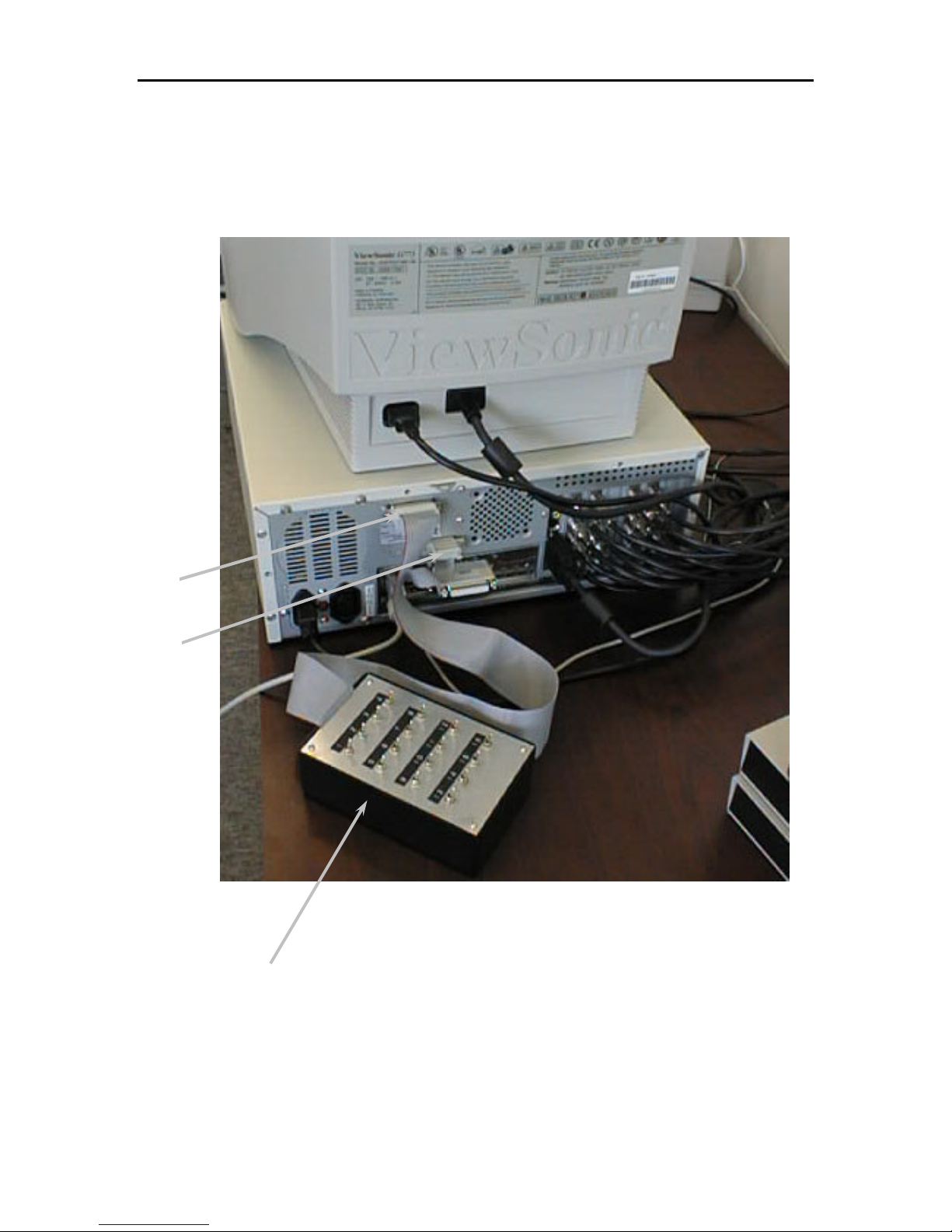
different from the original design. It is advisable the actual alarm connection should be
thoroughly checked with the type of tester shown before the system setup is released for
daily operation.
Note: Alarm input Tester (shown) is not part the DSR system.
www.elfinx.com TX-DSR04 Installation Guide Page 17 of 32
Page 18
Section 6 Installation of Alarm I/O components
input
input
TYPICAL CONFIGURATION
Alarm
Alarm
Alarm tester box
(Optional
www.elfinx.com TX-DSR04 Installation Guide Page 18 of 32
Page 19
Section 6 Installation of Alarm I/O components
25 24 23 22 21 20 19 18 17 16 15 14
15 14 13 1
2 11 10 9
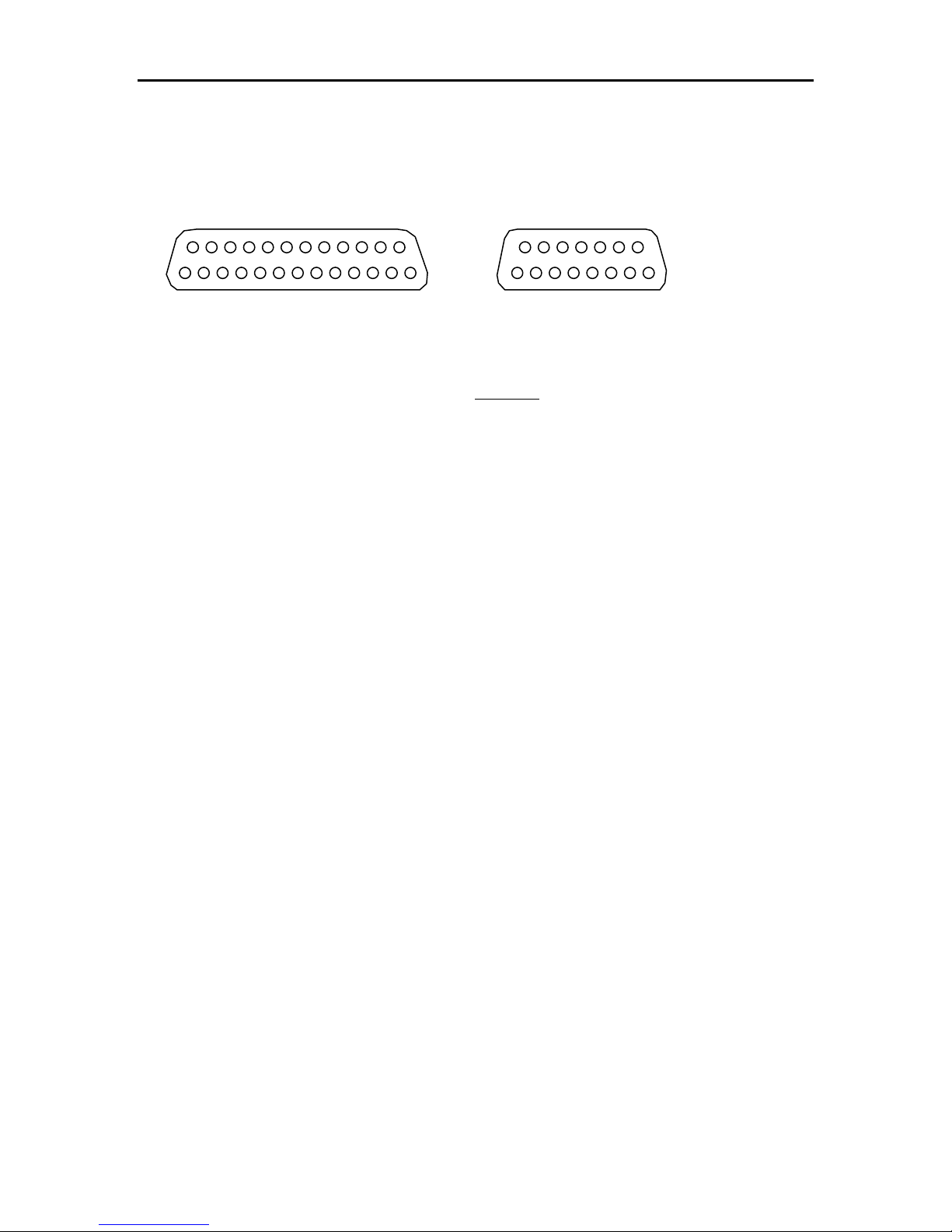
ALARM INPUT CONNECTION
External view of connectors
Connector #1 Connector #2
1 2 3 4 5 6 7 8 9 10 11 12 13
1 2 3 4 5 6 7 8
Alarm Input Connector #1
Pin No. Designations
Alarm Input/Output Connector #2
Pin
Designations
No.
1 Alarm input 1 1 Alarm input 13
2 Alarm input 2 2 Alarm input 14
3 Alarm input 3 3 Alarm input 15
4 Alarm input 4 4 Alarm input 16
5 Alarm input 5 5 Alarm output 1
6 Alarm input 6 6 Alarm output 2
7 Alarm input 7 7 Alarm output 3
8 Alarm input 8 8 N.C.
9 Alarm input 9 9 Gnd
10 Alarm input 10 10 Gnd
11 Alarm input 11 11 Gnd
12 Alarm input 12 12 Gnd
13 N.C. 13 Gnd
14 Gnd 14 Gnd
15 Gnd 15 Gnd
16 Gnd
17 Gnd
18 Gnd
19 Gnd
20 Gnd
21 Gnd
22 Gnd
23 Gnd
24 Gnd
25 Gnd
www.elfinx.com TX-DSR04 Installation Guide Page 19 of 32
Page 20

Section 6 Installation of Alarm I/O components
COLOR CODE OF ALARM INPUT AND OUTPUT CABLES
1. 24-core cable (Blue ring) to connector #1 (DB25 female connector)
Alarm Inputs #1 to 12
Color Code for 24-core cable (Blue Ring):
Pin 1-Alarm #1 input: R/Or Pin 14-Alarm #1 ground: Wh/G
Pin 2-Alarm #2 input: Bk/G Pin 15-Alarm #2 ground: Wh-Bk/R
Pin 3-Alarm #3 input: Bk/R Pin 16-Alarm #3 ground: Wh/R
Pin 4-Alarm #4 input: Bk/Or Pin 17-Alarm #4 ground: Wh/Bl
Pin 5-Alarm #5 input: R/Bl Pin 18-Alarm #5 ground: R/Bk
Pin 6-Alarm #6 input: Bk Pin 19-Alarm #6 ground: Wh/G
Pin 7-Alarm #7 input: Wh Pin 20-Alarm #7 ground: Bk/Bl
Pin 8-Alarm #8 input: G/R Pin 21-Alarm #8 ground: Bl
Pin 9-Alarm #9 input: G/Or Pin 22-Alarm #9 ground: R/Wh
Pin 10-Alarm #10 input: Or Pin 23-Alarm #10 ground: Bk/Wh
Pin 11-Alarm #11 input: Wh-R/Bk Pin 24-Alarm #11 ground: G
Pin 12-Alarm #12 input: Bk-R/Wh Pin 25-Alarm #12 ground: Wh/Bk
Pin 13-Not Used
2. 8-core cable (Blue ring) to connector #2 (DB15 female connector)
Alarm Inputs #13 to 16
Color Code for 8-core cable (Blue Ring):
Pin 1-Alarm #13 input: R Pin 9-Alarm #13 ground: Bk
Pin 2-Alarm #14 input: Y Pin 10-Alarm #14 ground: Wh
Pin 3-Alarm #15 input: Or Pin 11-Alarm #15 ground: Br
Pin 4-Alarm #16 input: G Pin 12-Alarm #16 ground: Bl
3. 6-core cable (Yellow ring) to connector #2 (DB15 female connector)
Alarm inputs #1 to 3
Color Code for 6-core cable (Yellow Ring):
Pin 5-Alarm #1 output: R Pin 13-Alarm #1 ground: Br
Pin 6-Alarm #2 output: G Pin 14-Alarm #2 ground: Bk
Pin 7-Alarm #3 output: Wh Pin 15-Alarm #3 ground: Bl
Pin 8-Not Used
Abbreviation:
R-Red G-Green Wh-White Bl-Blue Bk-Black
Br-Brown Or-Orange Y-Yellow
www.elfinx.com TX-DSR04 Installation Guide Page 20 of 32
Page 21

Section 7 Installation of Windows 98 OS
Section 7 Installation of Windows 98 OS
Installation of Windows98 SE to a new PC system for DSR
Before you begin
1. Make sure your computer meets the following minimum requirements:
Item OS only DSR-104 DSR-208 DSR-309A DSR-416
CPU speed 486DX66 or
higher
RAM 24 MB or
more
HDD space 140-400MB 2.5GB 4.0GB 6.5GB 8.4GB
MONITOR NTSC system PAL system
SVGA resolution with good
refresh rate, 72 Hz or above
at 16bit color
• CD-ROM or DVD-ROM drive for installation
• Microsoft Mouse or compatible pointing device
• For Remote access, using DSR Remote Intelligent Player, a 28800 baud or above
Modem, or a NIC of 10-Base-T or 100- Base-TX standard
• For audio recording capability, using DSR-xxxA Models or those with an Audio
Upgrade Patch installed, a sound card and a microphone
• Please refer to the related product brochure of the related model of DSR for other
Hardware compatibility requirements per specific model
2. Make sure you have a valid user license of the Windows98 OEM installation CD
if you use any of the Windows98 CD supplied, you may need to create a Setup
Floppy if you did not get one, please refer to the other section for detail
procedure.
PII350 PII350 PII450 PII450
64MB 128MB 128MB 128MB
800*600 1024*768
New Installation using the CD-ROM version of Windows 98
Before you start the following process, it is assumed that the hardware configuration of
the PC system unit is complete, the hard drive is partitioned and formatted with the
FAT32.file system. A Windows 98 Startup Floppy Disk is available or is prepared with
www.elfinx.com TX-DSR04 Installation Guide Page 21 of 32
Page 22

Section 7 Installation of Windows98 OS for a new system
the CD-ROM provided and a functional PC working with Windows 98. Please read the
application section for further details.
1. Insert a Windows 98 Startup Disk in the floppy disk drive.
2. Restart your computer.
The Microsoft Windows 98 Startup menu appears.
3. Insert the Windows 98 CD into your CD-ROM drive.
4. Type the number 1 and then press ENTER.
A series of scans is performed, and then the MS-DOS prompt appears.
5. At the MS-DOS prompt, type the word setup an then press ENTER.
A message informs you that Setup is going to perform a check.
If this message doesn’t appear, your computer can’t locate your CD-ROM drive.
For information about installing the correct CD-ROM driver, consult your drive
documentation or contact your hardware manufacturer.
6. Press ENTER.
Microsoft ScanDisk checks your disk drives for errors.
7. When ScanDisk finishes, press X.
After Setup initializes, Windows 98 Setup begins.
8. Follow the instructions that appear.
For information about specific screens and the information they request, see “Selecting
Setup Options.
Selecting Setup Options
During windows 98 installation, the Setup wizard may ask you to make some selections
and provide certain information. The following sections describe some of the wizard
screens and the information they request.
Product key screen
Type the Product Key in the spaces provided. The Product Key is located either on the
Certificate of Authenticity or on the back of your Windows 98 CD case. If the number
you type isn’t accepted, check the following:
• Make sure CAPS LOCK isn’t on.
• If you’re using the keypad to the right of your keyboard, make sure NUM LOCK is
on.
www.elfinx.com TX-DSR04 Installation Guide Page 22 of 32
Page 23

Section 7 Installation of Windows98 OS for a new system
• Make sure you aren’t using the letter “l” for number one.
• Make sure you aren’t using the letter “o” for the number zero.
Select directory screen
If you want to install Windows 98 files in a folder (directory) other than CWindows,
click Other Directory, click Next, and type the path to the folder you prefer. If you
specify a folder that doesn’t exist, the wizard creates the folder for you.
Setup Options screen
You can customize your version of Windows by choosing the components that are
installed on your hard disk. The Setup Options screen ask you to select the type of setup
your prefer. Choose Typical by clicking the button adjacent to it.
Select Component screen
On this screen, you can choose the options you want to install with Windows 98. Most
items in the Components list represents groups of options. For example, the Accessories
components contains several options, including Paint and the Discover the Windows 98
tutorial. To view the options that are included with a components click Details.
If necessary, click the selection box to include Dial-Up Networking from the
Communication group, select the ScanDisk and De-fragmentation from the Disk Tools
group.
Windows Components screen
On this screen, you choose whether or not to view a list of installation options.
If you select Install the most common components, Setup continues the installation. If
you select Show me that list of components so I can choose, the Select Components
screen appears. You then choose the individual options you want to install on your hard
disk. (See the Select Component screen section for details)
Identification screen
On this screen, you enter a name and descriptions for your computer. If your computer is
connected to a network, this information identifies your computer to other user and is
used by the Intelligent Remote Player.
Establishing Your Location screen
www.elfinx.com TX-DSR04 Installation Guide Page 23 of 32
Page 24

Section 7 Installation of Windows98 OS for a new system
On this screen, you should probably select the country in which you live. Some DVD is
coded for a specific region, so if you insert media that is coded for a region other than the
one you select here, it might not work properly.
Logging On to Windows 98
When you start Windows 98, the Welcome to Windows dialog box appears, asking you
to log on:
1. In the Welcome to Windows 98 dialog box, type your user name and password,
and then click OK.
Your password appears as asterisks (*) on the screen. If you don’t want t use a
password you can leave the box blank, and then click OK.
2. In the Set Windows Password dialog box, type your password again in the
Confirm New Password box, and then click OK.
The Windows 98 desktop appears. Installation is complete, and you can start
using Windows 98.
www.elfinx.com TX-DSR04 Installation Guide Page 24 of 32
Page 25

Section 8 Installation of Optional PC Peripheral Add-on’s
Section 8 Installation of optional PC peripheral Add-on’s
• Printer
• Modem
• Network Card
• Sound Card
• Removable IDE Harddrive
• SCSI Controller Card
• DVD RAM drive
• DAT Back up Drive
Before you start the installation of the Windows98 OS as per section 7 of this Manual, it is best to
install all the hardware such as the NIC (Network Interface Card), Sound Card and the Modem
Card into the system. Provided that the installed peripheral Add-on’s are included in our
hardware compatibility list, or it is know and common in the Plug and Play Categories of
standard, There is a high possibilities that drivers and plug-in will be automatically installed
during the succeeding process of he Windows98 OS installation.
Depending on the complexity of the driver setup, you may need to insert the drivers disk (of
selected Adapter Cards) and the Windows 98 CD ROM, alternately into the system for a couple
of time, and will need to restart the system a no. of time to complete the installation.
For individual Add-on board being installed as an upgrade, you can follow the similar procedure
as the UCC4 card installation for both hard ware and driver. Please see section 1 of the Manual
for details.
www.elfinx.com TX-DSR04 Installation Guide Page 25 of 32
Page 26

Section 9 Installation of Applications software
Section 9 Installation of Applications Software
Installation of DSR Application Software
From time to time, there is the need to re-install the Application software of the DSR system for
features upgrade or bug fix. Or as the PC system hardware being upgraded, we need to migrate
the DSR package module on to its new platform. Before you begin, make sure the Windows 98
SE Operating System is properly installed as per section 7 of this manual. Uninstall the previous
version of DSR Applications. Make sure the optional add-on boards (such as sound card,
modem, and video display or printer drivers) are installed or re-installed properly. The installation
instruction and tips for device setting of selected optional add-on boards are documented in both
the Section 8 of the Manual as well as in the related section of the DSR User Manual.
Installing the Software for DSR Digital Surveillance Recorder:
Notes: If you have an Installation CD ROM,for a dedicated model and customs specific option,
some of the installation options are automatically skipped. You will need to fill in only the detail of
your application and system configuration. Following procedures are applicable if you are
installing the Application software from a Software Pack Installation CD. (S-pack is for standard
models, A-Pack is for audio capable models, Full Pack is for both):
11. Insert “DSR Application CD” into the CD-ROM drive. The autorun will take place
immediately and a window of “DSR Application” menu will be shown on your
screen.
12. Select and click the Model and Options from the list and Click the “NEXT” button.
You may choose from Standard or Audio series of Model, NTSC or PAL
camera/video input system and other customs options. Follow all the procedures
outlined on the screen to finish installing the application software. In any of the menu
selection pages, if necessary, you may click the “BACK” button to roll back one level
for reselection.
13. At the Enter Options Code screen, use the default “450” and click “NEXT” for using
standard video Codec. Enter “1776” for MJPEG or “17743” for MPEG4 system, in
the latter cases, you will need to install the corresponding optional Codec into both
the DSR system as server (recorder) and the Client PC running the Intelligent Remote
Player. Please refer to section 5 of this Manual, Installation Instruction for optional
Video Compression Codec (s) for details.
14. Until the end of selection page, the setup program will load files into the PC and re-
starts your PC to complete the installation Process. You can Double Click the DSR
program icon from the Windows Desktop or Click (Once) the icon from the Status
Bar to launch the DSR Applications.
15. To Exit the program, click once on the EXIT button of the Main application Screen
and Click the “Yes” button to confirm.
www.elfinx.com TX-DSR04 Installation Guide Page 26 of 32
Page 27

Appendix I Storage Capacity Calculation
Appendix I Storage Capacity Calculation
A common question about the storage capacity
How can I setup recording with 16 and 8-camera inputs for continuous 24 hours, 48 hours and 72 hours of
recording? Can I retain 7 days of recording before overwriting it? What hard disk upgrade is needed so
that it can do 7-day recording before overwriting?
The recording capacity of DSR
DSR use advanced wavelet compression technology for real time video compression.
The average compressed frame size of a CIF resolution image (384x288 PAL, 320x240
NTSC) is about 8Kbytes. And the average frame size of a QCIF resolution image
(192x144 PAL, 160x120 NTSC) is about 3 Kbytes.
The maximum frame rate is 30 fps for NTSC system, and is 25 fps for PAL system.
However, when frame rate above 8 fps, the video will perform as real time like video.
The basic DSR configuration provides a 6GB hard disk for video recording.
Following is the equation that can be used to estimate the recording time of DSR.
Recording time (hr) = storage_size /(frame_size*fps*3600*no_of_camera)
Where storage_size is the storage size of the hard disk installed in the unit, frame_size is
the average compressed frame size for individual image, fps is the frame per second and
no_of_camera is the number of camera that are recorded.
Example:
When recording a camera in CIF resolution and real time recording at 25 fps, the 6GB
hard disk can provide about 8 hours of recording.
TEC00-015-A01 DSR Installation Guide Page 27 of 32
Page 28

Appendix I Storage Capacity Calculation
The recording frame rate of DSR
The following table tabulates the optimum performance of DSR recording.
Number of
camera
Average recording frame rate for each
camera
PAL NTSC
1 25 30
2 12 15
3 8 10
4 7 8
5 5 6
6 4 5
7 3 4
8 3 4
9 3 3
10 2 3
11 2 3
12 2 3
13 2 3
14 2 3
15 2 3
16 2 3
However, for time lapse recording, user can select the recording frame rate of each
camera. The possible frame rate for selection is listed in the following table.
The refresh rate selections
PAL NTSC
25 frame per
second
12.5 frame per
second
30 frame per
second
15 frame per
second
8 frame per second 7.5 frame per
second
4 frame per second 4 frame per second
1 frame per second 1 frame per second
1 frame per 2
second
1 frame per 2
second
1 frame per minute 1 frame per minute
Example:
For recording of 16 cameras in QCIF resolution (average compressed frame size 3Kbyte)
at 1frame per minute to a 6GB hard disk, the recording time can be calculated as follow:
Recording time (hr) = 6GB/(3K*(1/60)*3600*16) = 2083 hours = 87 days
TEC00-015-A01 DSR Installation Guide Page 28 of 32
Page 29
Appendix II Camera Info stored in the Registry
Value:
Appendix II Camera info stored in the Registry
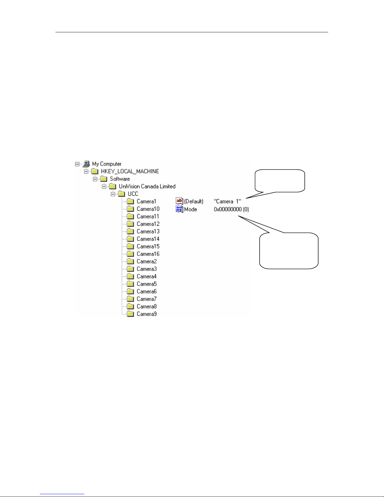
Camera Information Stored in the Registry
The camera information for UCC card is stored in the registry as follows:
String
DWORD
Value:
Camera Mode
www.elfinx.com TX-DSR04 Installation Guide Page 29 of 32
Page 30

Appendix III Compacting Database for DSR
Appendix III Compacting Database for DSR
Compacting Database for DSR
Each time the DSR records an AVI file, a new record is added into the database. While
deleting a file, the corresponding record is only marked as deleted but not deleted
physically. The database in DSR becomes bigger and bigger as the application running.
The database should be compacted to remove the useless records after a long time using.
There is a restriction to compact the database. It must be closed. We could put a
maintenance selection to let the user stop every recording and alarm arming to do this
compact. Also we could compact the database before the DSR2000.EXE starting.
To perform the compacting database for DSR, close all the instant and scheduled
recording of all attached cameras; exit the DSR program and than restart the DSR
application after a period of non-stop system operation.
SYSTEM MAINTENANCE
Schedule backup
and remove the
video file
Compact
Database system
The video files in the DSR unit should be backup and remove in
a regular basis with a properly setup schedule.
This will insure that the performance of the DSR unit is working
under its optimum condition.
It is also a vital procedure to prevent from data lose due to out of
storage space of the hard drive.
As a normal operation, it is recommended that user should log
off and turn off the DSR unit in a monthly basis.
This will allow the database to close and then do some
optimization and compacting of the record configuration during
the system power up.
www.elfinx.com TX-DSR04 Installation Guide Page 30 of 32
Page 31

Appendix IV DSR Package Specification
Appendix IV DSR Package Specification
DSR-416 Package
Digital Video Surveillance Recording
• DSR-416 package product is designed to support the building of digital video
surveillance recording system. When integrated with the networking over Local Area
Network (LAN) or Dial Up, Lease Phone Lines, Wide Area Network (WAN), it
provides the support to the optional Remote Intelligent Playback Function.
• The completed system* provides the following features:
Digital multi-channel video recorder and multiplexer
Support up to 16 camera inputs with multi display modes
Support both PAL and NTSC standards
Easy to use graphic user interface
Full resolution video real-time display (768x576 PAL, 640x480NTSC)
Real-time digital video compression
Simultaneous playback, recording and live display
Programmable timer recording
Alarm triggered recording
Motion detection recording
Pre-alarm recording
Easy to expand by software upgrade and system integration
Multilingual capability
Pan/Tilt/Zoom control of the connected cameras (optional)
• The completed system provides platform for system integration with other security
control systems, such as access control, fire alarm or automation, ID/smart card
system, intrusion detection, etc.
• The product is designed to run on a Pentium II or above PC with a Windows
operating system.
• The product (Base and remote client package) will consist of video capture board(s)
with compression, plus the application software and user manual.
*Dealer installation and system integration is applicable
For DSR-416 package product technical specification, please refer to the DSR Digital
Surveillance Recorder standard product brochure.
www.elfinx.com TX-DSR04 Installation Guide Page 31 of 32
Page 32

Appendix IV DSR Package Specification
Hardware Recommendation
CPU Pentium III 450 or above Pentium 233MMX or above
Motherboard Intel 82440 GX (or BX) based
Memory 128MB SDRAM (PC 100) 64MB SDRAM
Display SVGA display with 1024x768,
Network 10/100Base T or Modem 10/100Base T or Modem
Harddisk 10.2GB 4.3GB
Operating System Window 98
Recorder Package
(DSR standard)
with adequate number of PCI slot
or equivalent (see Note iii)
16M color
Plus IE 5.0 or above
Remote Player Package
No special preference
SVGA display card
Window 98
Plus IE 5.0 or above
DSR-416 Package Model No.
DSR[K]-416 DSR Digital Surveillance Recorder Package, Support up to 16 video
input, 16-alarm input and 1 output.
DSR-SIRP DSR Intelligent Remote Player Software Package
Notes:
i. Adaptive hardware option is provided to meet individual performance requirement
of the user.
ii. For details of package product, please refer to the respective information sheet.
iii. Each UCC4 card required a PCI slot on the motherboard; additional PCI slot may be
required for the video display card etc. Depending on the PC configuration. (Each
UCC4 card will support 4 camera inputs).
Order Information
DSR-416 Package for Digital Video Surveillance Recorder is the keep
component of the total solution of the Security Industry. The system has
the ability to provide remote video playback and management of the
recorder video data. Cross system interface can be provided via LAN or
WAN with digital network communication for data and control. Nearly
every integrated video surveillance system, which cannot make use of a
compact system, is normally dealt with as a custom project.
Quotations of a complex project are given on application.
Please contact Dealer offices sales support to define the required configurations and in
order to check the availability and suitability of the various modules per application.
www.elfinx.com TX-DSR04 Installation Guide Page 32 of 32
 Loading...