

Elexa Level mount ELSFW-01, Level mount DC30SW, Level mount LM30SW Installation Instructions Manual
Installation Instructions
www.LevelMount.com
24-7 Help Desk Line
1-888-229-1459
©2008 Level Mount
Patents Pending
VESA 200 X 100 Low Profile - Model:
ELSFW-01, LM30SW, DC30SW
DO NOT RETURN THIS PRODUCT TO THE STORE OR WEB
SITE YOU PURCHASED IT FROM!
IF YOU BELIEVE THIS MOUNT IS DEFECTIVE, HAS
MISSING OR BROKEN PARTS, OR IF YOU ARE HAVING
DIFFICULTY INSTALLING THIS MOUNT TO YOUR WALL
OR FITTING YOUR TV, PLEASE CONTACT OUR COMPANY,
LEVEL MOUNT, DIRECTLY.
Dial 1 888 229 1459 or email us at CustomerSupport@
ElexaUSA.com any time of the day or night for a quick and
efficient solution to your problem.
Our trained Customer Service Department is open 24 hours
a day, 7 days a week, every day of the year and is prepared
to assist you in both English and Spanish.
Please also visit our Web Site at www.LevelMount.com
for assistance.
CAUTION:
Installer must make sure the LCD/Plasma Wall Mount
is properly and securely attached and that appropriate fasteners are used. It is the responsibility of the
installer to verify that the mount is anchored properly
to the wall.
PLEASE NOTE: THE MOUNT MUST BE ATTACHED
TO WOOD STUDS OR TO PROPERLY INSTALLED
PLASTIC ANCHORS IN MASONRY OR CONCRETE.
DO NOT MOUNT ONLY TO DRY WALL.
Before installing check to make sure all parts of the
mount are included.
Make sure all screws and bolts are tightened before
allowing Wall Mount to bear the full weight of the
Plasma/LCD.
Features:
• Integrated Bubble Level
• Easy 2 Piece Mounting
• Low Profile Design
• Stud Finder Included
Mounting Hardware Included:
Bag REF Description QTY
1 A Phillips M4 x 12 Bolt 4
B Phillips M4 x 20 Bolt 4
C Phillips M4 x 30 Bolt 4
D M4 Lock Washer 4
2 E Phillips M5 x 12 Bolt 4
F Phillips M5 x 20 Bolt 4
G Phillips M5 x 30 Bolt 4
H M5 Lock Washer 4
3 I Phillips M6 x 12 Bolt 4
J Phillips M6 x 24 Bolt 4
K Phillips M6 x 35 Bolt 4
L M6 Lock Washer 4
4 M 3/4’’ Spacer 4
5 N 2.5’’ Wood Screw 2
O Concrete Anchor 2
Tools required for attachment to stud:
Stud Finder
1/16’’ Drill Bit
Tools required for attaching to concrete:
Electric drill
2/5’’ (10mm) Masonry Bit
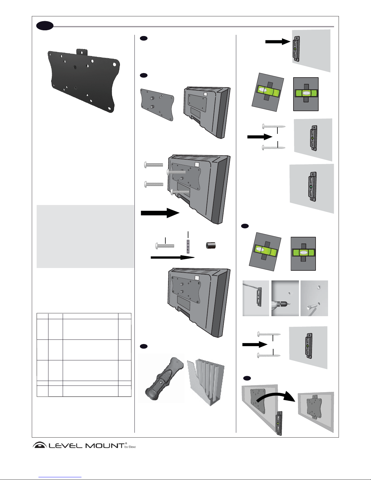
DETERMINE CORRECT BOLT
Caution: Carefully thread the bolt into the back of your
LCD to determine which bolt is to be used. If there is any
resistance remove the bolt immediately.
ATTACH TO TV
ATTACH TV TO WOOD STUDS
Locate stud with Stud Finder
(See manual included)
ATTACH TV TO CONCRETE
SLIDE TOGETHER
English
1
2
3a
3b
4
(USE SPACER ONLY
IF NEEDED)
N
N
LOCK WASHER
BOLT
Instrucciones de instalación
www.LevelMount.com
Línea de asistencia las 24 horas
1-888-229-1459
©2008 Level Mount
Patentes pendientes
VESA 200 X 100 con diseño discreto - Modelo: ELSFW-01, LM30SW,
DC30SW
NO DEVUELVA ESTE PRODUCTO A LA TIENDA O
SITIO WEB EN EL QUE LO COMPRÓ.
SI EL SOPORTE ESTÁ DEFECTUOSO, PRESENTA
PARTES ROTAS O LE FALTAN PIEZAS; SI TIENE
DIFICULTADES PARA MONTARLO EN LA PARED O
PARA COLOCAR EN ÉL SU TELEVISOR, PÓNGASE
EN CONTACTO DIRECTAMENTE CON LA EMPRESA
LEVEL MOUNT.
Si desea obtener una solución rápida y eficaz para
su problema, llame al 1-888-229-1459 o envíenos un
mensaje de correo electrónico a CustomerSupport@
ElexaUSA.com, a cualquier hora del día o de la noche.
Nuestro personal del departamento de atención al
cliente es muy competente, está disponible de manera
permanente durante todo el año y le atenderá tanto en
inglés como en español.
Si desea obtener más información, acuda a nuestro sitio
Web www.LevelMount.com
PRECAUCIÓN:
Al realizar la instalación, asegúrese de que el soporte
de pared para televisores LCD/Plasma está colocado
de forma correcta y segura, así como de que utiliza los
sujetadores adecuados. El instalador es responsable de
comprobar que la base esté sujeta adecuadamente a la
pared y al televisor.
TOME NOTA DE LO SIGUIENTE: LA BASE DEBE ESTAR
FIJA A TRAVESAÑOS DE MADERA O A ANCLAJES
PARA MAMPOSTERÍA O CONCRETO QUE ESTÉN
CORRECTAMENTE INSTALADOS. NO SE DEBE FIJAR
DIRECTAMENTE EN EL YESO (DRY WALL).
Previamente a la instalación, asegúrese de que dispone de
todas las piezas para realizar el montaje.
Asegúrese de que todos los tornillos y los pernos estén
bien apretados antes de apoyar completamente el peso
del televisor LCD o de plasma sobre la base.
Características
• Nivel de burbuja integrado
• Construcción de 2 piezas, de fácil instalación
• Diseño discreto
• Se incluye un detector de travesaños
En el producto se incluyen las siguientes piezas de montaje:
KIT REF Description CANT
1 A Perno de cruz M4 x 12 4
B Perno de cruz M4 x 20 4
C Perno de cruz M4 x 30 4
D Arandela de seguridad M4 4
2 E Perno de cruz M5 x 12 4
F Perno de cruz M5 x 20 4
G Perno de cruz M5 x 30 4
H Arandela de seguridad M5 4
3 I Perno de cruz M6 x 12 4
J Perno de cruz M6 x 24 4
K Perno de cruz M6 x 35 4
L Arandela de seguridad M6 4
4 M Espaciador de 3/4’’ (1,9 cm) 4
5 N Tornillo para madera de 2,5’’ 2
O Anclaje para concreto 2
Herramientas necesarias para la fijación a travesaños:
Detector de travesaños
Broca de 1/16” (2 mm)
Herramientas necesarias para la fijación a paredes de
mampostería o concreto
Taladro eléctrico de mano
Broca de 15/32’’ (12 mm) para pared
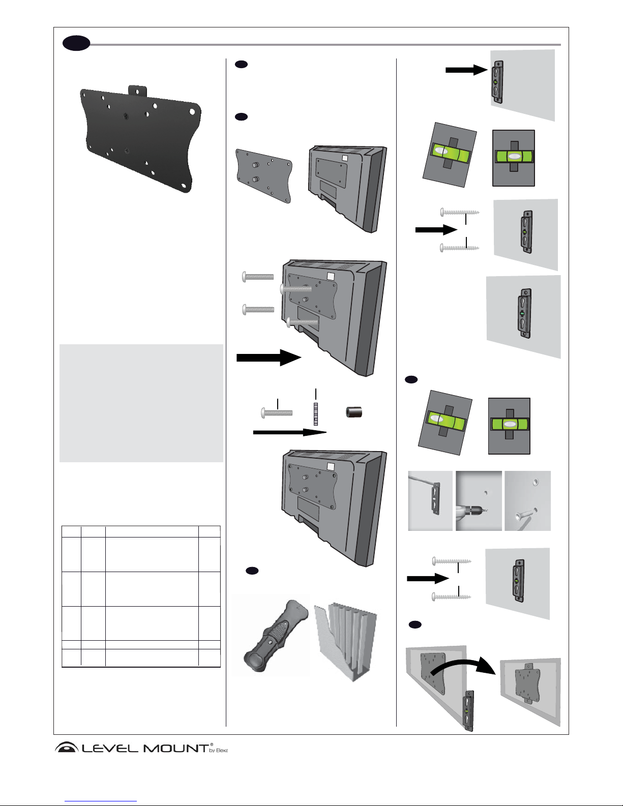
ELIJA EL TORNILLO ADECUADO
Precaución: Para determinar qué tornillo deberá usarse,
enrosque manualmente el tornillo en la parte trasera de
su televisor LCD. No siga enroscando si los tornillos no
encajan perfectamente.
AJUSTAR AL TELEVISOR
FIJE EL TELEVISOR A LOS
TRAVESAÑOS DE MADERA
Ubique el travesaño con el detector
(Consulte el manual incluido)
FIJE EL TELEVISOR A LA PARED
DESLIZAR Y UNIR
Espanol
1
2
3a
3b
4
(UTILICE EL ESPACIADOR SÓLO CUANDO
SEA NECESARIO)
N
N
RANDELA DE SEGURIDAD
TORNILLO
 Loading...