

Elevated Access Sinoboom GTJZ1412, Sinoboom GTJZ1414 Maintenance Manual
GTJZ1412
& GTJZ1414
Maintenance Manual
0800 222 111 sales@elevatedaccess.co.nz
021 500 486 www.elevatedaccess.co.nz

GTJZ1412 & GTJZ1414 Maintenance Manual
Key Points
Before maintaining the machine, it is necessary to
read, understand and observe those safety rules,
operation instructions and maintenance instructions.
Only the trained and authorized personnel are allowed
to maintain the machine. It is necessary to always
keep this Manual along with the machine as a part of
it. Please contact with Hunan SINOBOOM Heavy
Industry Co., Ltd.
Table of Contents
Importance ....................................................... 2
afety Rules .................................................... 2
S
Product Performance Parameters .................... 4
Operating Procedures ...................................... 8
Regular Maintenance Procedures ................... 8
Procedure A ........................................... 13
A-1 Inspect All Manuals ............... 13
A-2 Inspect All Labels .................. 13
A-3 Inspect Damaged, Loose or
Lost Parts ....................................... 13
A-4 Inspect Hydraulic Oil Level .. 14
A-5 Inspect Hydraulic Oil Leakage14
A-6 Functional Tests ..................... 14
A-7 Carry out Maintenance after 30
Days............................................... 14
A-8 Inspect Battery
....................... 15
Procedure B ........................................... 16
B-1 Inspect Electric Wires ............ 16
B-2 Inspect Rim and Tire (Including
Mounting Nuts) ............................. 16
B-3 Test Key Switch ..................... 17
B-4 Test Emergency Stop Buttons 17
B-5 Test Horn................................ 17
B-6 Test Braking Device .............. 17
B-7 Testing Traveling Speed
(Platform in Lifted State) .............. 18
B-8 Testing Traveling Speed
(Platform in Fully Retracted State)18
B-9 Test Full Lifting and Full
Lowering Time .............................. 18
B-10 Ins
pect Hydraulic Oil ........... 19
B-11 Check the hydraulic tank
ventilation system ......................... 19
Procedure C ........................................... 20
C-1 Replace Air Filter of Hydraulic
Oil Tank ........................................ 20
C-2 Inspect Platform Weighing
System (Optional) ......................... 20
Procedure D ........................................... 20
D-1 Inspect Scissor Arm Installation
Bearing .......................................... 20
D-2 Inspect Base Frame Slider ..... 20
D-3 Replace Return Oil Filter of
Hydraulic Oil Tank........................ 20
Procedure E ........................................... 21
E-1 Inspect and Re
place Hydraulic
Oil .................................................. 21
Maintenance Procedures ............................... 22
Platform Components ........................... 23
1-1 How to Remove Electric
Control Box from Platform ........... 23
1-2 How to Remove Platform ....... 23
1-3 How to Remove Extension
Platform ......................................... 23
Scissor Arm Part.................................... 24
2-1 How to Remove Scissor Arm . 24
2-2 How to Remove Lifting
Cylinder ......................................... 24
Base Frame Components ...................... 25
3-1 How to dismantle the brake .... 25
3-2 How to dismantle
the driving
motor ............................................. 25
3-3 How to Remove Storage Battery26
3-4 How to Remove Hydraulic
Valve Block ................................... 26
3-5 How to dismantle the hydraulic
power unit ..................................... 26
3-6 How to Remove Hydraulic Oil
Tank ............................................... 26
3-7 How to Remove Steering Oil
Cylinder of Front Wheel ............... 27
3-8 How to dismantle the front
wheel bracket ................................ 27
Hydraulic System .................................. 27
4-1 Detection of Function Pump... 27
4-2 How to Remove H
ydraulic
Pump ............................................. 28

GTJZ1412 & GTJZ1414 Maintenance Manual
4-3 Control valve block on the
platform ......................................... 29
4-4 Symbols of Hydraulic System 33
4-5 Hydraulic Schematic Diagram 34
Electrical System................................... 35
5-1 Use and Maintenance of
Lead-Acid Storage Battery ........... 35
5-2 Trouble Diagnosis (Deltatech
System) .......................................... 40
5-3 Fundamental Troubleshooting 43
5-4 Electrical Symbols .................. 46
5-5 Electrical Schematic Diagram
(Deltatech system) ........................ 47
1
Importance
Hazard
Warning
Caution
Caution
Attention
GTJZ1412 & GTJZ1414 Maintenance Manual
You have understood and observed the safe
operation rules in the operation manual
Before maintaining GTJZ1412 it is necessary to read,
understand and observe corresponding safety rules
and operation instructions.
This Manual provides detailed maintenance
information for the owner and the operator, and
specifies inspection, maintenance and troubleshooting
methods and procedures for the competent
professional maintenance personnel.
The execution of maintenance procedures requires
basic knowledge on
machinery, hydraulic and
electrical aspects. Some maintenance procedures need
special skills, tools, lifting equipment and appropriate
work place. Therefore, it is strongly recommended to
maintain and repair at the designated service center of
the SINOBOOM.
Hunan SINOBOOM Heavy Industry Co., Ltd. will
provide accurate information and quality services.
However, the products will be improved continuously
and technical specification of prod
uct may be
modified without advance notice. We suggest the
users to update latest product maintenance
specifications regularly.
We will appreciate if the customers could inform us
the deficiencies of the products and propose
improvement measures. We will consider all
suggestions carefully and use them as the reference
for the preparation of maintenance specification and
other specifications. Please contact us by E-mail or
fax.
You shall have read, understood and observed
—Manufacturer’s in
structions and safety rules
—User’s safety rules and workplace regulations
—All the applicable government regulations
You must use appropriate tools, lifting
equipment and work place.
Personal safety
All working staff on or around the machine must be
aware of any possible safety hazards. The personal
safety and the continuous and safe operation are the
most important.
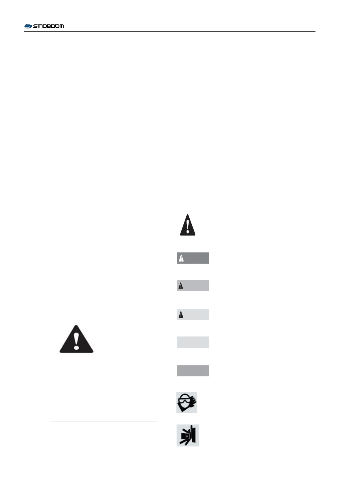
Read the procedures carefully. The marks used in the
labels in
this manual and on the machine are defined
as follows:
Safety warning mark- It is used to prompt
potential personal injuries. Observe all
safety prompts behind this mark for the
purpose of avoiding personal injuries or
death.
Red mark- It is used to prompt the urgent
hazardous cases; if not avoided, it would
lead to death or serious injuries.
Orange mark- It is used to prompt
potential hazardous cases
it would lead to death or serious injuries.
; if not avoided,
Saf
ety Rules
Hazard
Failure to observe the instructions in this Manual and
corresponding operation manual would cause death or
serious injury accident.
Pay attention to the unsafe operations mentioned in
the operation manual when carrying out maintenance
procedures.
Do not operate, unless:
Orange mark with safety warning- It is
used to prompt potential hazardous case;
if not avoided, it might lead to mild or
moderate personal injury.
Orange mark without safety warning- It is
used to prompt potential hazardous case;
if not avoided, it might lead to property
losses.
Green mark- It is used to prompt
operation or maintenance information.
It is necessary to wear protective goggles,
and work clothes.
With potential hazards such as movable
parts, components which could rotate
2

GTJZ1412 & GTJZ1414 Maintenance Manual
freely or have not been fixed, lifting or moving weight.
Be sure to wear work boots.
Safety in Work Place
Keep sparks, flame and lit cigarette end
away from flammable and explosive
materials such as storage battery and
engine fuel. Equip qualified fire
extinguisher nearby.
Maintain all tools and work place
properly for future use. Ensure the
working environment to be clean and
prevent the sundries or fragment dropping
into the machine compo
Ensure good ventilation and illumination
conditions in the work place and working
area.
Ensure any forklift, traveling crane or
other lifting/supporting equipment to
have sufficient bearing and lifting
capacity. Ensure to use steel wire rope or
belt with sufficient bearing capacity and in good
condition.
nents, resulting in damages.
Do not use disposable fasteners (such as
split pins and self-locking nuts)
repeatedly. The componen
become invalid if they are used again.
Dispose the used hydraulic oil and other
fluid appropriately. Use appropriate
container. Protect the environment from
being polluted.
ts might
3
Width
Height
Maximum platform height
Maximum working height
Maximum horizontal
extension
Hydraulic system
GTJZ1412 & GTJZ1414 Maintenance Manual
Product Performance Parameters
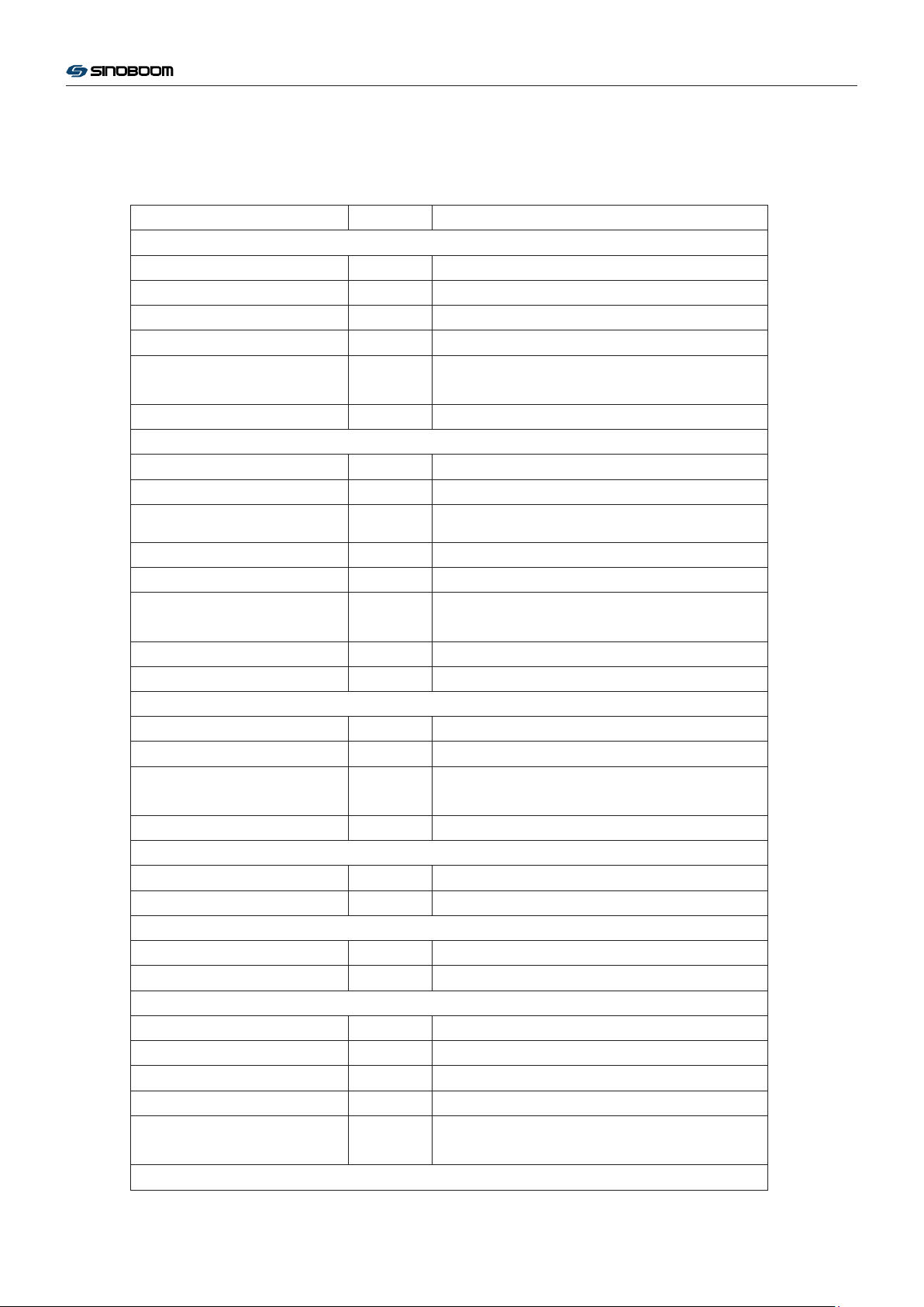
Parameter Items Unit GTJZ1412
Outline dimension
Length
Ground clearance mm 100
Ground clearance (Pithole
protective device stretches)
Total weight kg 3364
Design dimension
m 2.76
m 1.25
m 2.60
mm 22
m 13.8
m 15.8
m 0.9
Maximum bearing capacity kg 227
Extended platform bearing capacity kg 120
Allowable quantity of people
working on the platform
Wheel base m 2.22
Wheel span m 1.25
Turning radius
Internal wheel m 0
External wheel m 2.56
Maximum allowable yawing force
(indoor/outdoor)
Control voltage (DC) V 24
Platform dimensions
Length m 2.64
Height m 0.81
Tire size
Diameter mm 380
Height mm 125
Oil volume
Hydraulic oil tank L 14
Pressure of hydraulic system bar 240
System voltage (DC) V 24
Maximum noise for normal
working
Traveling speed
Person 2 (indoor)/1 (outdoor)
N 400/200
L 42 (Oil tank)
dB 72
4

GTJZ1412 & GTJZ1414 Maintenance Manual
Off-running status km/h 0~3.2
Lifting status km/h 0~0.8
Gradeability % 25
Lifting/lowering time s 83s~92s /55s~65s (No load)
Maximum allowable wind speed
(indoor/outdoor)
Maximum allowed inclined
angle
m/s 0/12.5 (Gale Level 6)
Front and rear 3°/Left and right 1.5°
5

GTJZ1412 & GTJZ1414 Maintenance Manual
Description of Hydraulic System
Normal temperature region (0℃ to 40℃):
L-HM46;
Cold region (-25℃ to 25℃): L-HV32;
Hot region
(>40℃): L-HM68;
Extremely cold region
(<-30℃):
Special scheme to be determined;
Different hydraulic oil may be filled in
according to the requirements of the customer
upon delivery.
Hydraulic pump
Type Gear pump
Flow rate (at 3000r/min) 12L/min
Maximum driving pressure 248bar
Traveling motor
Type Orbit motor
Displacement 375cc/r
Functional valves
Pressure of function main safety valve 248bar
Pressure of lifting overflow valve 210bar
Pressure of steering overflow valve 120bar
Pressure of travelling overflow valve 248bar
Opening pressure of travelling brake 28 bar
Oil return filter
Oil return filter of hydraulic oil tank SP-06×10
Bypass pressure of oil return filter 2.5bar
6

GTJZ1412 & GTJZ1414 Maintenance Manual
Installation Instructions for Hydraulic Hoses and
Fittings
When removing or installing the hydraulic hoses and
fittings with O-ring, it is necessary to operate as per
the torque specified in the following table.
Hose fittings
Thread Torque Nm
G1/8A 20±1
G1/4A 35±2
G3/8A 50±3
G1/2A 75±5
G3/4A 120±8
G1A 180±10
G1 1/4A 240±15
7/16-20 21±2
Hoses
Thread Torque Nm
M12×1.5 19±1
M14×1.5 26±2
M16×1.5 40±3
M18×1.5 50±4
M22×1.5 70±5
M26×1.5 90±6
M30×2 120±8
M36×2 150±12
Tightening Procedures
1. Replace the O-ring. It is necessary to replace the
O-ring if the seal has been damaged. The O-ring
shall not be reused if the pipe fitting or the hose
has between tightened.
2. Lubricate the O-ring before installation.
3. Ensure to place and fix the O-ring properly.
4. Align the hose nut to the pipe fitting, and tighten
the nut.
5. Tighten the nut or the pipe fitting as per the
torque specified
6. Perform all machine functions and inspect hoses,
hose fittings and relevant components to confirm
that no leakage occurs.
in the above table.
7

Warning
GTJZ1412 & GTJZ1414 Maintenance Manual
Operating Procedures
Energy
4 sets of 6V lead-acid cell in series for driving of a
24V DC motor. The gear pump is connected to the
output shaft of the motor with the spline to provide
power for the system.
Hydraulic System
All functions of the machine are driven by a hydraulic
system which is divided into two parts: one for the
travelling and steering functions and the other for the
lifting function of the platform.
When the motor i
the pressure oil to the function valve block which is
equipped with a directional valve and a flow
regulating valve for performing different actions and
adjusting the speed. In order to protect relevant
components and avoid overload of system pressure, a
relief valve is installed on the valve block.
Electrical System
4 separate 6V batteries are used in the system to drive
the hydraulic pump and drive
the lift function of the lift arm. The storage batteries
are re-charged with external power supply.
Machine Control
s working, the hydraulic pump sends
a controller that controls
Regular Maintenance Procedures
Compliance
The maintenance and inspection should be
completed by trained and competent personnel.
The regular maintenance inspection consists of
daily, quarterly, semiannual, annual and biennial
maintenance. The maintenance and inspection
personnel must inspect and maintain according
to the maintenance and inspection reports, and
fill in
maintenance and inspection reports in
details.
Warning: Failure to carry out
maintenance procedures
specified herein timely and
regularly may lead to death, serious injury or machine
damages.
The damaged or troubled machine must be
labeled and moved away timely.
The functions of the machine are controlled with one
controller in this system. This controller is installed in
the ground control box. The controller exchanges data
through a high-speed data bus.
Safety Measures
A series of angle sensors and limit switches provides
signals to the con
the angle of vehicle body on axis X and axis Y; when
the angle on axis X exceeds 1.5° or the angle on axis
Y exceeds 3°, the alarm will be triggered, and the
machine could not lift, travel or turn.
Travel switch shall be used to confirm if the pit
protective mechanism is opened enough. If the
platform is lifted off ground by 2.5m, the pit
protective plate is not stretched, and the sens
detected the signals, the platform will stop rising.
trollers. The level sensor measures
or has not
The damaged or troubled machine must be
repaired before operation.
All records shall be stored for at least three
years.
The machine which has not bee
over three months must be subjected to quarterly
inspection.
Unless otherwise specified, the maintenance
procedures shall be carried out according to the
following precautions:
Park the vehicle on level firm ground
Engage the platform in loaded state
Turn the key switch to the position “OFF” and
take down the key
Turn the red emergency stop buttons on
platform controller and ground controller to the
position “OFF”
onnect all DC power supplies on the
Disc
machine
n maintained by
Lock the tires
8
Hazard
Warning
Caution
Caution
Attention
GTJZ1412 & GTJZ1414 Maintenance Manual
Description
This section provides detailed operation procedures
for the regular maintenance and inspection.
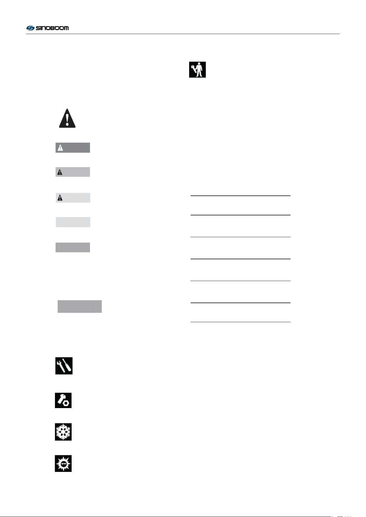
Symbol Definition
Safety warning mark- It is used to prompt
potential personal injuries. Observe all safety
prompts behind this mark for the purpose of
avoiding personal injuries or death.
Red mark- It is used to prompt the urgent
hazardous cases; if not avoided, it would lead to
death or serious injuries.
Orange mark- It is used to prompt potential
hazardous cases; if not avoided, it would lead to
death or serious injuries.
Orange mark with safety warning- It is used to
prompt potential hazardous case; if not avoided,
it might lead to mild or moderate personal injury.
Orange mark without safety warning- It is used
to prompt potential hazardous case; if not
avoided, it might lead to property losses.
Green mark- It is used to prompt operation or
maintenance information.
Maintenance Symbol Definition
The following symbols are
Attention
the intent of this specification. If one or several
symbols are marked in front of the maintenance
procedure, it is defined as follows:
used in this manual for
helping the reader understand
Indicate that this operation must be carried
out by the supplier
Maintenance Schedule
There are five types of repair & inspection to be
carried out according to the schedule: Every day,
every quarter, every six months, every year and every
two years. With consideration to the repeated
procedures, the
“Regular Repair Procedure Section”
and the “Repair & Inspection Report” shall be
classified into five sections- A, B, C, D and E. The
necessary procedure combination for regular
inspection shall be determined according to the
following table.
Inspection Interval Inspection Procedures
Every day or every 8 hours A
Every quarter or every 250 hours A+B
Every half a year or every 500 hours A+
Every year or every 1,000 hours A+B+C+D
Every two years or every 2,000 hours A+B+C+D+E
B+C
Repair & Inspection Report
The repair & inspection report shall include the
inspection table of each regular inspection.
Indicate the tools for carrying out this
operation
Duplicate the repair & inspection report for each
inspection. Store the completed tables by over three
Indicate new parts for carrying out this
years.
operation
Indicate that hydraulic motor must
be
stopped before carrying out this operation
Indicate that hydraulic motor must be
started before carrying out this operation
9

Attention
GTJZ1412 & GTJZ1414 Maintenance Manual
Pre-delivery Inspection:
It is quite necessary to carry out the preparation before
delivery.
Carry out this procedure each time before delivery for
the convenience of finding before putting the machine
into service whether there are any obvious errors.
Damaged or troubled machine shall not be used. It is
necessary to label and move away the machine if
finding damaged or abnormal machine.
The machine repair must be completed b
competent repair personnel strictly according to the
repair manual.
Daily maintenance must be completed by the
competent operator according to the provisions of this
Manual.
y the
Description:
Use the operation manual for this machine.
The preparation before delivery includes inspection
before delivery, maintenance procedures and
functional inspections.
Record the inspection results. If any inspection result
is N, it is necessary to stop the machine, repair the
machine and then re-inspect the machine, and mark R.
Notes:
Y—Yes, the machine is in good condition.
N—No, the machine has trouble.
R—Repaired, the machine has been repaired.
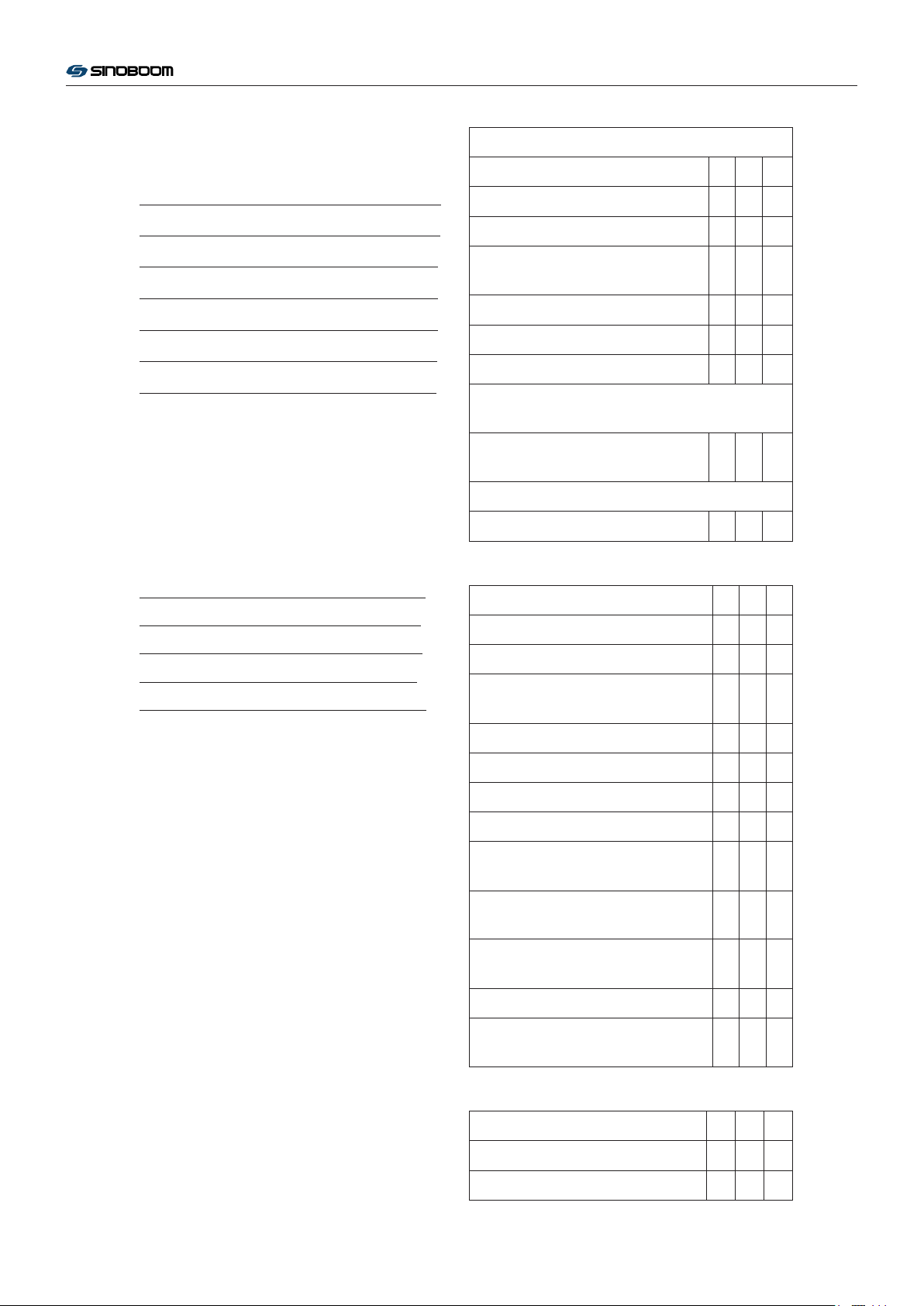
Record Form of Preparation before Delivery
Items Y N R
Inspection before
Delivery
Maintenance Procedures
Functional Inspections
Model
Serial No.
Date
User
Signature of Inspector
Position of Inspector
Organization of Inspector
10
GTJZ1412 & GTJZ1414 Maintenance Manual
Maintenance Record Form:
Model
Serial No.
Date
User
Signature of Inspector
Position of Inspector
Organization of Inspector
Description:
Record the following results after inspection on each
step.
Time Interval Inspection Procedures
Record Form A
Items Y N R
A-1 Inspect All Manuals
A-2 Inspect All Labels
A-3 Inspect Damaged, Loose or Lost
Parts
A-4 Inspect Hydraulic Oil Level
A-5 Inspect Hydraulic Oil Leakage
A-6 Functional Inspections
Carry out Inspections of New Vehicle after 40
Working Hours
A-7 Carry out Maintenance after 30
Days
Carry out Inspections Every 125 Hours
A-8 Inspect Battery
Every day or every 8 hours A
Every quarter or every 250 hours A+B
Every half a year or every 500 hours A+B+C
Every year or every 1,000 hours A+B+C+D
Every two years or every 2,000 hours A+B+C+D+E
Inspect according to the steps in this section to get
acquainted with the inspection procedures.
Record the inspection results. If any inspection result
is N, it is necessary to stop the machine, repair the
machine and then re-inspect the machine, and mark R.
Notes:
Y—Yes, the machine is in good condition.
N—No, the machine has trouble.
R—Repaired, the machine has been repaired.
Record Form B
Items Y N R
B-1 Inspect Electric Wires
B-2 Inspect Rim and Tire (Including
Mounting Nuts)
B-3 Test Key Switch
B-4 Test Emergency Stop Buttons
B-5 Test Horn
B-6 Test Braking Device
B-7 Test Traveling Speed (Platform in
Lifted State)
B-8 Test Traveling Speed (Platform in
Fully Retracted State)
B-9 Test Full Lifting and Full Lowering
Time
B-10 Inspect Hydraulic Oil
B-11 Inspect Ventilation System of
Hydraulic Oil Tank
Record Form C
Items Y N R
C-1 Replace the hydraulic oil tank air
11

filter
GTJZ1412 & GTJZ1414 Maintenance Manual
C-2 Inspect Platform Weighing
System (Optional)
Record Form D
Items Y N R
D-1 Inspect Scissor Arm Installation
Bearing
D-2 Inspect Base Frame Slider
D-3 Replace Return Oil Filter of
Hydraulic Oil Tank
Record Form E
Items Y N R
E-1 Inspect and Replace Hydraulic Oil
12

Procedure A
Attention
Attention
A-1 Inspect All Manuals
GTJZ1412 & GTJZ1414 Maintenance Manual
A-3 Inspect Damaged, Loose or Lost Parts
Storing the operation manual and the maintenance
manual in appropriate place is of great importance to
the safe operation of the machine. The manuals shall
be stored in the dedicated storage box on the platform.
The illegible or damaged manuals could not provide
necessary safety and operation information for safe
operation.
1. Inspect and confirm that the document box is
placed on appropriate po
2. Inspect and confirm that the operation manual
and the maintenance manual are stored in the
storage box on the platform properly.
3. Inspect the pages of the manuals and confirm that
they are legible and intact.
4. Return the manual into the storage box after use.
Heavy Industry Co., Ltd.
A-2 Inspect All Labels
sition of the platform.
If needing to replace the
manual, please contact
with Hunan SINOBOOM
Inspecting the condition of the machine daily is of
great importance to the safe and reliable operation of
the machine.
damaged, loose or lost parts have not been found and
repaired timely.
Observe the entire machine and check whether any
parts are damaged, installed improperly or lost,
including:
Electrical components, wirings and cables
Hydraulic power unit, oil tank, fittings, hoses,
Storage battery pack and its connection
Driving motor, brake device and fastening bolts
Tyre and fastening nut
Power unit
Limit switch and horn
It would lead to unsafe operation if the
hydraulic cylinders and valve blocks
Maintaining all safe
great importance to the safe operation of the machine.
The labels are used to prompt the operator the
potential risks in the operation process, and
meanwhile provide operation and maintenance
information to the user. The illegible labels could not
guide the operator properly, and might result in unsafe
operation.
1. Consult to the label section in the “GTJZ1412
Operation Manual” and determine the
positions of the labels according to the label list
and chart.
2. Inspect whether all labels are legible and intact;
replace the damaged and illegible labels timely.
Hunan SINOBOOM Heavy Industry Co., Ltd.
ty and prompt labels properly is of
correct
If needing to replace the
labels, please contact with
Alarms and indicator lamps (if provided)
Nuts, bolts and other fasteners
Intermediate hurdles of entrance or door for
platform
Pit-hole protector
Extended zone of platform
Pivot of scissors arm and fastener
Platform joystick
Fastening bolts on the sliding block of the
platform
13
 Loading...