

Elettronika TXUP5000 User Manual

_______________________________________________________________________________________________
Section 1 - Information
Contents:
1.1 Description
1.2 Technical characteristics
49
AUTV/1500LD
LDMOS - UHF TV AMPLIFIER
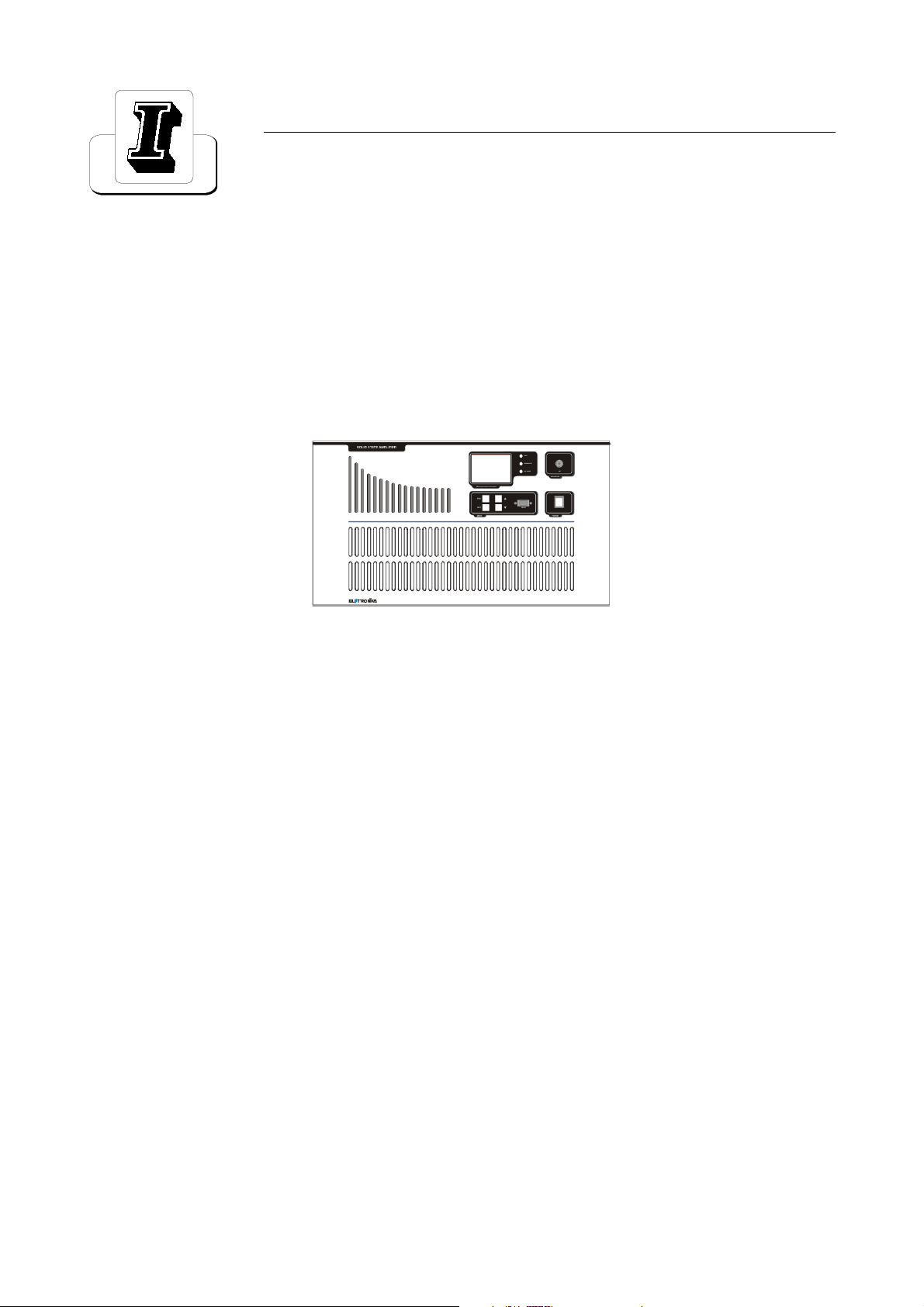
1.1 DESCRIPTION
The AUTV/1500LD is an amplifier operating into Band IV-V for common amplification process of the Vision
and Sound carriers.
The amplifier has been designed to offer to the customer high performances, high reliability and greater
simplicity in his operation and maintenance procedures.
The amplifiers modules employ all solid state LDMOS technology in order to obtain high gain, wideband performances, very good linearity, reliability and high efficiency.
The equipment design allows the soft degradation (RF power loss) for several transistor faulty: in fact the
output combiner uses RF power resistors for unbalancing power dissipation. The unit is enclosed in a cabinet
for 19- 6U rackmounting.
50

1.2 TECHNICAL CHARACTERISTICS
RF
Frequency range 470 - 860MHz
Output power 1300W PEP
Video/Sound power ratio 10/1
Out stage technology Solid State LDMOS
Vision-Sound amplification Common
I.M.D. (-8, -10, -16dB) Better than -54dB
Standards G, K, N
Spurious and harmonics level In compliance with CCIR rec.
RF Output impedance 50W
RF Output connector 7/16
GENERAL
Power supply 230Vac, ±10%, 50/60Hz
Power consumption 3400VA at black level
RS232 Socket DB9 Connector (on front panel)
RS485 Socket DB9 Connector (on rear panel)
Telemeasuring socket DB9 Connector (on rear panel)
AGC Socket DB9 Connector (on rear panel)
Power factor > = 0.9
Ambient temperature -5° to +45°C
Relative humidity 20% - 90%
Altitude Up to 2.500 meters
Cooling Forced air
Cabinet Rack 19-6U
Dimensions 760x263x266mm
Wei ght 70kg
400Vac 3P+N (on request)
PROTECTION THR.
FWD Power 1500W
REF Power 150W
Unbalacing 350W
Temperature 75°C
I
DC
V
DC
25A
Min 10V - Max 33,5V
51

This page is intentionally blank
52
_______________________________________________________________________________________________
Section 2 - Installation
Contents:
2.1 Operating environment
2.2 Preliminary operations
2.3 Telemeasuring socket connections
2.4 RS232, RS485 and AGC socket connections
2.5 Preventive maintenance
- Front panel
- Rear panel
53
2.1 OPERATING ENVIRONMENT
You can install the apparatus in a standard component rack or on a suitable surface such as a bench or desk.
In any case, the area should be as clean and well-ventilated as possible. Always allow for at least 2 cm of
clearance under the unit for ventilation. If you set the apparatus on a flat surface, install spacers on the bottom
cover plate. If you install the apparatus in a rack, provide adequate clearance above and below. Do not locate
the apparatus directly above a hot piece of equipment.
2.2 PRELIMINARY OPERATIONS
Correct installation of the equipment is important for maximum performance and reliability. Antenna and earth
connections must be installed with the greatest care. The equipment adjustment isnt need, because the unit is
completely adjusted by our technical staff. This is the installation procedure:
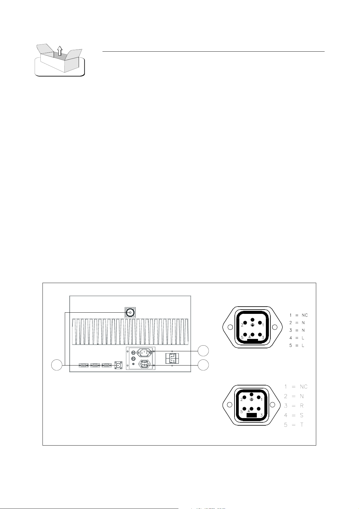
1. connect the power supply cable of the exciter to the auxiliary socket on the rear panel of the amplifier;
2. connect the power supply cable of the amplifier to the electric network (230VAC). If there is the Isolator
Transformer, the amplifier is provided with cable and plug;
3. connect the exciter / antenna cables respectively to the RF IN and RF OUT on the rear panel of the
amplifier.
WARNING!!!
FOR ELECTRICAL SAFETY REASONS AND IN ORDER TO KEEP
THE APPARATUS SAFE, THE GROUND TERMINAL OF THE
APPARATUS MUST BE CONNECTED TO THE EXISTING GROUNDING SYSTEM AND NOT BY USING THE SHIELD OF THE OUTPUT
COAXIAL CABLE.
Monophase cabling
2
13
Three-Phase cabling
54
When the apparatus is put within a combined system it is directly connected to the input splitting and output
combining systems.
Before fully powering the apparatus, check that the output connections of the coaxial cable to the antenna
system are working.
In order to this it is possible to check the indication of the reflected power at low power levels. Only if the
SWR indication on the display is 0, the output power can be slowly increased. At maximum output power,
some watts might be shown as reflected power.
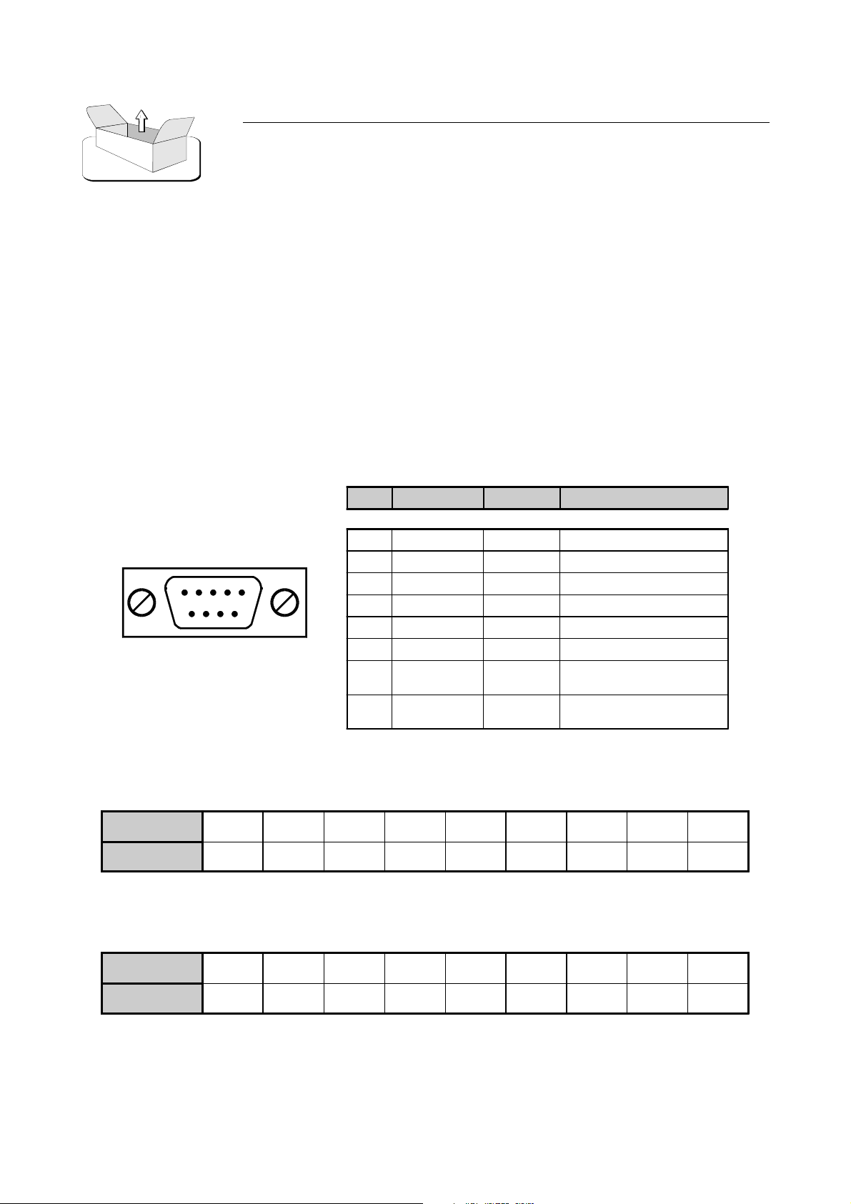
2.3 TELEMEASURING SOCKET CONNECTIONS
PIN N° SIGNAL TYPE IN / OUT FUNCTION
1 Analog Output FWD P o wer
2 A nalog Output REF Power
3 Digital Output Temperature
4 Digital Input Interlock
5GND - -
DB9 Socket
6 - 7 Digital Output Free contact (closed when alarm)
8 Digital Input
9 Digital Input
0V = ON
5V = Normal
0V = OFF
5V = Normal
2.4 RS232, RS485 AND AGC SOCKET CONNECTIONS
PIN
FUNCTIONS
PIN
FUNCTIONS
1234 56 789
-TxDRxD-GND----
RS232 - DB9 Socket
1234 56 789
-Rx-Rx+5VGND-Tx-Tx+-
RS485 - DB9 Socket
55
PIN N° SIGNAL TYPE IN / OUT FUNCTION
1GND - -
2 Digital Output
3 Digital Output
8 Analog Output FWD Powe r
9 Analog Output FWD Powe r
AGC - DB9 Socket
0V = Normal
5V = AGC Alarm
0V = Normal
5V = AGC Alarm
2.5 PREVENTIVE MAINTENANCE
To ensure maximum performance and minimum repair trouble, we strongly recommend you to follow the
below stated headlines for preventive maintenance:
1. check antenna installation and ground connection at regular intervals;
2. keep your apparatus clean and dry externally: this will ensure continuous functioning of the front panel
controls;
3. if the apparatus has not been used for a long period of time combined with exposure to extreme environmental conditions, open the unit and make a visual inspection.
Remove salt, water or ice with a moist cloth before turning the apparatus on. Check that the cooling fans are
running freely.
4. for general maintenance and top performance, call an authorized service technician to give the apparatus
and the complete antenna/earth connection installation a general check every 12-18 months;
5. check at regular intervals that the air intake located on the front panel is free of dust. If there is visible dust,
remove it by means of a soft brush.
56
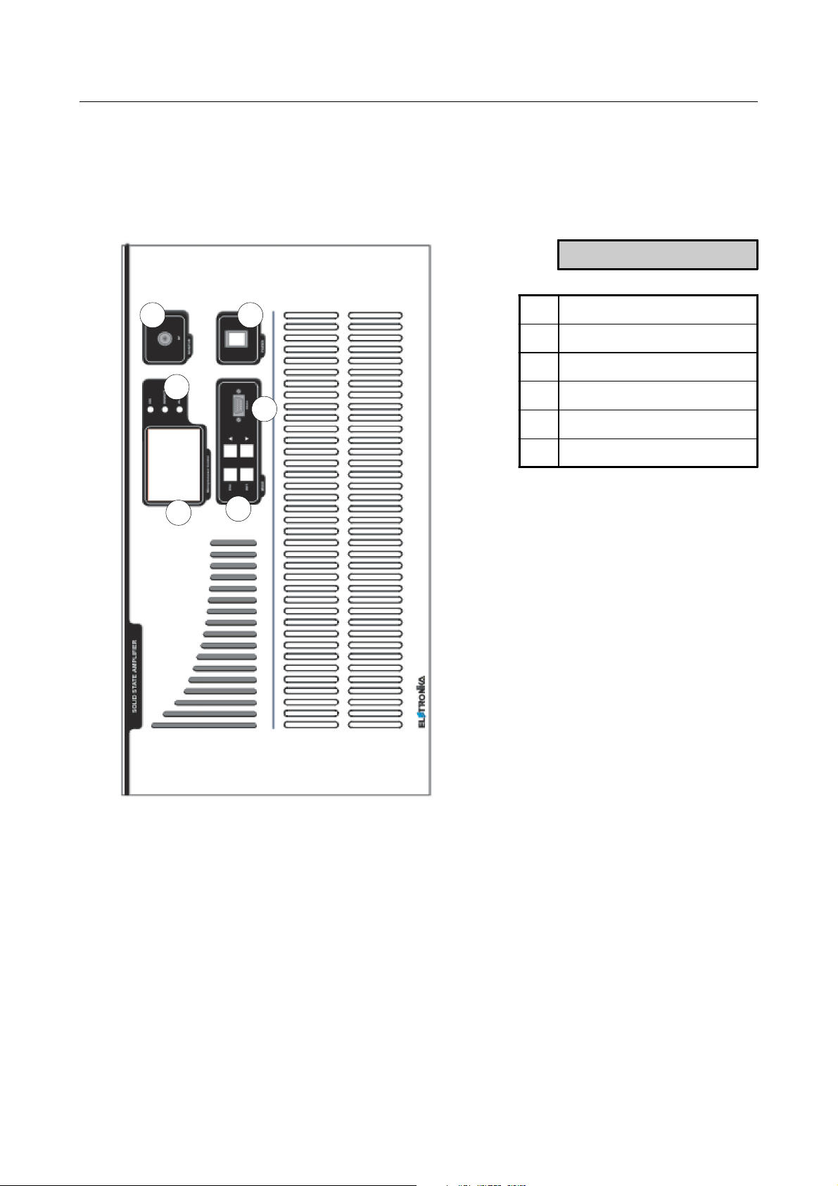
Front panel
DESCRIPTION
4
5
3
1LCD Display
2 Function keys
3 Status LEDs
4 RF Monitor connector
6
5 Main switch
6 RS232 Socket
1
2
57
Rear panel
DESCRIPTION
1
1 Breaker
2 Power supply socket
3 Auxiliary socket
3
2
4
9
8
4Fuse
5 RS485 Socket
6 AGC Socket
7 Telemeasure socket
8 RF Input connector
9 RF Output connector
7
6
5
58
_______________________________________________________________________________________________
Section 3 - Operation
Contents:
3.1 Control board and display description
3.2 Operation
3.3 Display
3.4 Menu
59

3.1 OPERATION
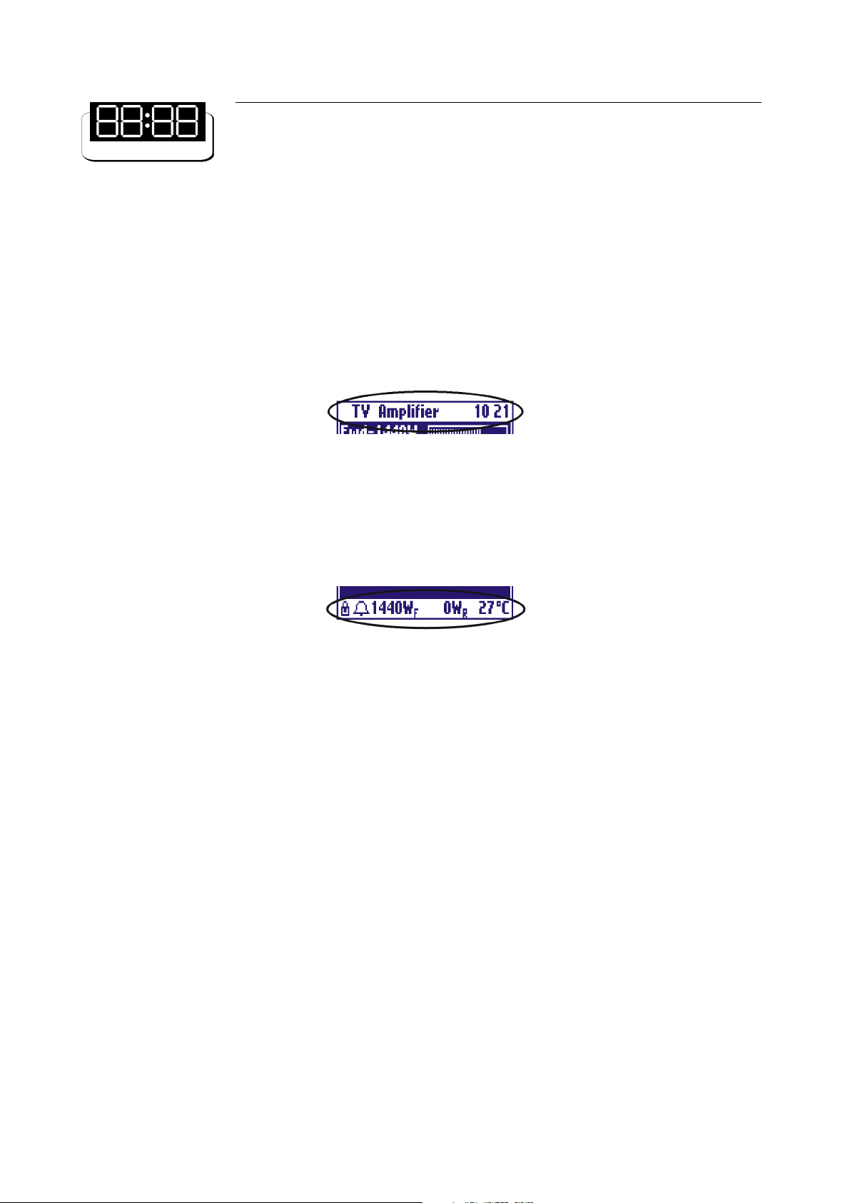
At startup, after intro image, the display shows the main screen, showing the RF powers as in Figure 1:
Figure 1: Main screen
The user may turn on and off the amplifier by means of the switch on the front panel. The control board turns
on all the power supplies, the exciter, if any, and the cooling fans. While the amplifier is working, the microcontroller monitors continuously the most important parameters: power supply voltages, absorbed currents,
temperature, forward and reflected power, unbalances, if any. Each signal is associated to a maximum threshold
beyond which the amplifier is immediately put in protection status by turning off one or more power supply,
depending on the failed block. In order to prevent a temporary problem to trigger a definitive protection
status, the failed block is turned on again for up to five times. If it goes beyond the protection threshold for
more than five times, it is declared as FAILED and will no longer be turned on. In this case the amplifier will
have to be turned off manually by means of the switch on the front panel, then turned on again after performing
the needed maintenance. On the front panel there are also three LEDs labelled ON, REMOTE and ALARM.
Their meanings are explained below.
LED COLOUR MEANING MEANING WHEN BLINKING
The amplifier has been turned on
ON Green The amplifier is on
REMOTE Yellow
ALARM Red Alarm status It never blinks
Table 1: Meanings of the three LEDs on the front panel
1
Screenshots in this manual are indicative and they refers to a TV amplifier, so they can be different from those on your equipment.
60
Remote control is
enabled
locally but it has been turned off by
remote
It ne ve r b l i nk s
3.2 DISPLAY
The control board is provided with a modern 128x64 pixels graphic display with blue backlight. Normally it
always shows a title bar (on the top line) and a status bar (on the bottom line).
The title bar, see Figure 2, shows the name of the amplifier (TV Amplifier or FM Amplifier) and the current
time.
Figure 2: Title bar
The status bar indicates the forward and reflected power and the temperature. It also contains two symbols
for the interlock (lock) and a generic alarm (bell).
Figure 3: Status Bar
The bell symbol is displayed in case of alarm. It blinks if there has been an alarm which has ended but has not
yet been seen by the user. It stops blinking once the alarm Log has been checked.
The interlock symbol is displayed only when the check for this alarm is enabled. It may be either a close lock,
see Figure 3, when there is no alarm (close interlock chain) or an open lock in case of alarm (open interlock
chain).
Since the status bar is always on the display, regardless of the displayed screen, the user may monitor at any
moment the most important parameters and the presence of alarms, if any, while moving between different
screens.
3.3 MENU
The user may see or modify locally some configuration parameters of the apparatus by means of the four keys
on the front panel. All screens are made up by hierarchical menus and the user may move between them in a
simple and intuitive way.
To see the main menu its sufficient to press ESC key (see Figure 4).
61
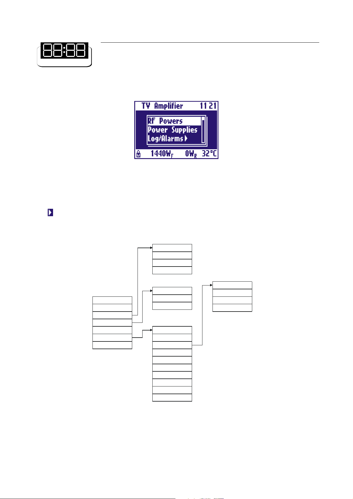
Figure 4: Main menu
The display only shows three items, but the whole menu can be scrolled by means of the UP and DOWN
arrow keys. Any item can be chosen by selecting it and pressing the RET key. Menu entries with arrow on the
right open sub-menus when chosen. Thus there is a hierarchical structure as in Figure 5. To go back from
a sub-menu to the previous menu, press the ESC key. If the ESC key is pressed in the main menu, the main
powers screen is accessed.
View Log/Alarms
Clear Log/Alarms
Log Mode
Exit
RF Powers
Power Supplies
Log/Alarms >
Working Timer >
Thresholds
Settings >
Exit
Figure 5: Hierarchical menu structure
All menu items are described in detail below.
View Timer
Timer Reset
Exit
RMS/Peak
Date/Time
Display
Frequency
Slave Address
Remote
Interlock
Release
Serial Number
Exit
Backlight
Contrast
Screensaver
Exit
62
- RF Powers
This is the main screen showing the RF powers of the amplifier: forward power, reflected power, unbalances,
if any. For forward power a level bar is displayed. See example in Figure 1.
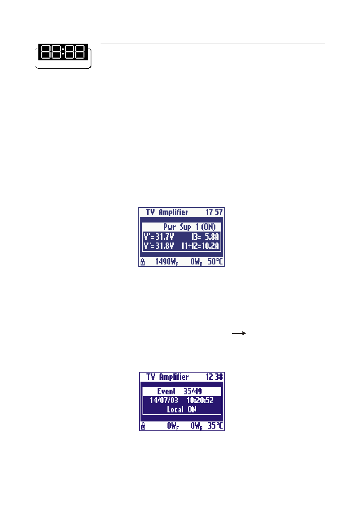
- Power Supply
This screen shows all the signals coming from the power supply. To check a different power supply press the
UP (or DOWN) key to see the next (or previous) one. For each power supply, the two voltages, the two
absorbed currents and the status (ON or OFF) are shown.
Figure 6: Power supply screen
- Log/Alarms
The control board is provided with an external EEPROM and a clock. Any alarm or switching event is saved
into an event log stored inside the EEPROM and associated to the time at which it occurred. The Log/Alarms
sub-menu allows to manage this log.
It is possible to see the events stored in the log by selecting Log/Alarms View Log/Alarms. All events
can be scrolled by pressing the UP and DOWN keys. The event shown in Figure 7 is the turning on of the
amplifier by means of the local switch. Each event is associated to the date and time at which it occurred and
to a description.
Figure 7: Event stored in the log
63
In case of alarm on a parameter, the value of the parameter which caused the alarm is saved into the log. In
case of alarm still existing after five turning-on attempts, the parameter is marked as FAILED. Table 2 is the
list of all the events which can be logged.
EVENT DESCRIPTION
Local ON Amplifier turned on by means of the local switch
Local OFF Amplifier turned off by means of the local switch
Remote ON Amplifier turned on remotely
Remote OFF Amplifier turned off remotely
Interlock opened Interlock chain opened
Interlock closed Interlock chain closed
Power Supply ON Power supply on
Fwd Pwr xxxxW Alarm fo r forward power
Ref P wr xxxxW Alarm for reflec ted p owe r
UnbY xxxxW Unbala nci ng alarm
Pwr Sup x: V1 xx.xV Power supply voltage alarm
I1 xx.xA Power supply current alarm
Pwr Sup x: OVERVOLT Power supply overvoltage alarm
Pwr Sup x: OVERTEMP Power supply overtemperature alarm
Table 2: Events managed and logged by the control board
The log may be completely deleted by selecting Log/Alarms Clear Log/Alarms.
Amplifier can store in the log details about alarms and generic events. You can change this behaviour selecting
Log/Alarms Log/Mode menu item.
- Working Timer
The control board has a working timer which is always enabled while the amplifier is working (i. e. there is at
least one power supply working). The menu entry Working Timer View Timer allows to check the hours
for which the timer has been enabled. Working Timer Timer Reset resets the timer.
- Thresholds
This is a screen showing the alarm threshold of each and all signals monitored by the control board. The list
can be scrolled by means of the UP and DOWN keys.
64
- RMS/Peak
The control board can monitor both the RMS and peak powers. The menu entry Settings RMS/Peak
allows to choose the power to be displayed and monitored.
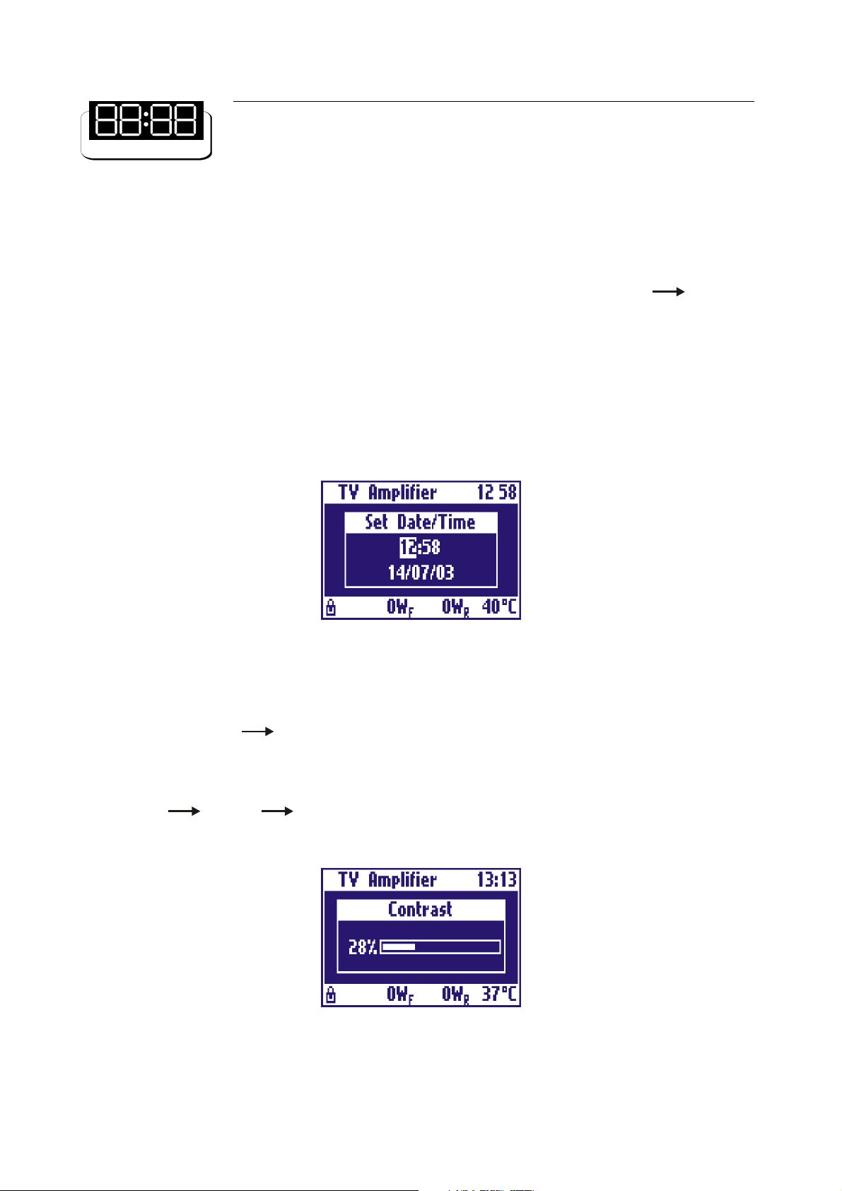
- Date/Time
This screen allows to set the current date and time. The setting is changed by pressing the arrow keys, then
pressing the RET key to move to the following setting and eventually save the changes. To go back to the
previous menu and discard any change made, press the ESC key. Figure 8 shows an example of this screen.
Figure 8: Date and time setting screen
- Display
The menu entry Settings Display allows to change some settings of the display, such has back light,
contrast and screensaver. The back light and the contrast are set by means of the UP and DOWN arrow
keys. The changes made are saved by pressing the RET key or discarded pressing the ESC key. Figure 9
shows the contrast screen.
With Settings Display Screensaver you can set an interval time after which display backlight is
turned off. When display backlight is off, press any key to switch it on.
Figure 9: Display contrast setting screen
65
 Loading...