

Elettronika AUTV/5000LD, AUTV/3500LD User Manual

AUTV/5000LD
LDMOS - UHF TV Solid State Amplifier
Users manual
CODE: APT120A TITLE: AUTV/5000LD REV: 0 DATE: 22/10/03

SS 96 Km 113
70027 Palo del Colle (Ba) ITALY
Tel. +39 (0)80 626755
Fax +39 (0)80 629262
E-mail: elettronika@elettronika.it
Web siste: http://www.elettronika.it
Registration number: IT-17686
Registration number: IT-24436

3
WARNING
The apparatus described in this manual has been designed and manufactured with devices to safeguard the users. In any case it is recommended that during any operation of installation, maintenance,
miscellaneous interventions and calibrations requiring the apparatus to be switched on,
THE USER TAKES ALL THE
PRECAUTIONS AGAINST INCIDENTS
It is required to use the proper clothes and protection gloves in order to prevent damages from incidental contacts with high-voltage parts.
The manufacturer declines every responsibility in case the recommendations above are not followed.
IMPORTANT
The component lists attached to the relevant electrical diagrams indicate for each item the reference,
the description and the type normally used.
The Elettronika S.r.l. though reserves the right to use or supply as spare parts components with
equivalent characteristics but of a different type, assuring anyway the optimal work of the apparatus
in accordance with the specifications.
The enclosed monographs are solely owned by Elettronika S.r.l.
The use of anything enclosed in this technical manual without explicit authorization given by Elettronika
S.r.l. will be prosecuted by the law.
The data and technical characteristics of the apparatus described in this manual are not compelling for
the manufacturer.
The Elettronika S.r.l. reserves the right to make, without previous notice, modifications or updates in
order to improve the quality of the product.
The general conditions of supply and sale are described in the contracts.
The delivery time are in accordance with the products and quantities ordered.

4
Summary of warranty
We, ELETTRONIKA S.r.l., SS096 Km 113 Z.I. PALO DEL COLLE (BA) ITALY, warrant to the ORIGINAL PURCHASER of a NEW product, for a
period of one (1) year from the date of purchase by the original purchaser (the warranty period) that the new ELETTRONIKA product is free of defects
in materials and workmanship and will meet or exceed all advertised specifications for such a product. This warranty does not extend to any subsequent
purchaser or user, and automatically terminates upon sale or other disposition of our product.
Items excluded from this ELETTRONIKA warranty
We are not responsible for product failure caused by misuse, accident, or neglect. This warranty does not extend to any product on which the serial
number has been defaced, altered, or removed. It does not cover damage to loads or any other products or accessories resulting from ELETTRONIKA
product failure. It does not cover defects or damage caused by use of unauthorized modificstions, accessories, parts, or service.
What we will do
We will remedy any defect, in material or workmanship (except as excluded), in our sole discretion, by repair, replacement, or refund. If a refund is
elected, then you must make the defective or malfunctioning component available to us free and clear of all liens or other encumbrances. The refund will
be equal to the actual purchase price, not including interest, insurance, closing costs, and other finance charges less a reasonable depreciation on the
product from the date of original purchase. Warranty work can only be performed at our authorized service centers or at our factory. Expenses in
remedying the defect will be borne by ELETTRONIKA, including one-way surface freight shipping costs within the United States. (Purchaser must bear
the expense of shipping the product between any foreign country and the port of entry in the United States and all taxes, duties, and other customs fee(s)
for such foreign shipments).
How to obtain warranty service
You must notify us of your need for warranty service not later than ninety (90) days after the expiration of the warranty period. We will give you an
authorization to return the product for service. All components must be shipped in a factory pack or equivalent which, if needed, may
Desclaimer of consequential and incidental damages
You are not entitled to recover from us any consequential or incidental damages resulting from any defect in our product. This includes any damage
to another product or products resulting from such a defect.
Warranty alterations
No person has the authority to enlarge, or modify this warranty. The warranty is not extended by the lenght of time for which you are deprived of
the use of the product. Repairs and replacement parts are provided under the terms of this warranty shall carry only the unexpired portion of this
warranty.
Design changes
We reserve the right to change the design of any product from time to time without notice and with no obligation to make corresponding changes in
products previously manufactured.
Legal remedies of purchaser
There is no warranty which extends beyond the terms hereof. This written warranty is given in lieu of any oral or implied warranties not contained
herein. We disclaim all implied warranties, including without limitation any warranties of merchantability or fitness for a particular purpose. No action
to enforce this warranty shall be commenced later than ninety (90) days after expiration of the warranty period.
Warranty for electronic tubes
The warranty applied for electronic tubes is the one given by the manufacturer of the tube. In the event that the product shows anomalies within the
deadline of the validity of the warranty given by the manufacturer of the product itself, the buyer will have to return it to the seller with the needed
documents and the written description of the defect. The seller will ship the broken tube to the manufacturer in order to effect the necessary technical
tests to find out the cause of the anomaly. Meanwhile the buyer of the tube who needs to use, and as such to replace immediately the product, will have
to buy a new one and provide to the relevant payment, further to the issuing by the seller of a regular commercial invoice. After the adequate tests made
by the manufacturer, should the result be positive, that is confirm the defect in manufacturing, the seller will issue a regular credit note in the name of
the buyer and return the amount paid. Should the result be negative, that is detect a negligence in the installation or use by the buyer, he will have no
right against the seller.
Warranty

5
INTRODUCTION
The apparatus described in this manual is the latest of this series, offering high performances, remarkable reliability and a wide range of characteristics, it all at a low cost.
Its is easy to install and use. It only takes to follow the installation procedure as shown in this manual:
after having removed all from the package, you only have to follow step by step the description in the
various sections.
Before starting to use the apparatus, remember to:
read carefully the general safety information contained in this section;
follow the instructions for the installation and set up of the apparatus;
read all the remaining sections of this manual in order to know well the apparatus and learn
how to obtain the best of its characteristics.
CONTENTS OF THE MANUAL
The chapter composing this manual contain all the information concerning the use of the apparatus.
For more information refer to ELETTRONIKA S.r.l.
This manual is made up of different chapters, each made up of various sections. Each individual
chapter represents a single apparatus composing the whole station.

6
WARNING!
The currents and voltages in this equipment are dangerous!
Personnel must at all times observe safety regulation!
This manual is intended as a general guide for trained and qualified personnel who are aware of the
dangers inherent in handling potentially hazaedous electrical and electronic circuits.
It is not intended to contain a complete statement of all safety precautions which should be observed by
personnel in using this or other electronic equipment.
The installation, operation, maintenance and service of this equipment involves risks both to personnel
and equipment, and must be performed only by qualified personnel exercising due care.
Elettronika S.r.l. shall not be responsible for injury or damage resulting from improper procedures or
from the use of improperly trained or inexperienced personnel performing such tasks.
During installation and operation of this equipment, local building codes and fire protection standards
must be observed.
WARNING!
Always disconnect power before opening covers,
doors, enclosures, gates, panels or shields.
Always use grounding nsticks and short out high
voltage points before servicing. Never make
internal adjustments, perform maintenance or
service when alone or when fatigued.
Do not remove, short-circuit or tamper with interlock switches on access covers, doors, enclosures,
gates, panels or shields.
Keep away from live circuits, know your equipment and dont take chances.
WARNING!
In case of emergency ensure that power has been disconnected.

7
A - AIRWAY
If unconscious, open airway lift up neck, push
forehead back, clear out mouth if necessary,
observe for breathing.
Treatment of electrical shock
1) If victim is not responsive follow the A, B, Cs of basic life support.
PLACE VICTIM FLAT ON HIS BACK ON A HARD SURFACE
B - BREATHING
If not breathing, begin artificial breathing. Tilt
head, pinch nostrils, make airttght seal, 4 quick
full breaths. Remember mouth to mouth resuscita-
tion must be commenced as soon as possible.
C - CIRCULATION
Check carotid pulse. If pulse
absent, begin artificial circulation.
Approx. 80sec.: 1 rescuer, 15 compressions, 2 quick breaths.
Approx. 60sec.: 2 rescuers, 5 compressions, 1 breath.
NOTE: DO NOT INTERRUPT RHYTHM OF COMPRESSIONS WHEN
SECOND PERSON IS GIVING BREATH.
Call for medical assistance as soon as possible.

8
2) If victim is responsive:
- keep them warm;
- keep them as quiet as possible;
- loosen their clothing (a reclining position is recommended).
FIRST-AID
Personnel engaged in the installation, operation, maintenance or servicing of this equipment are urged
to become familiar with first-aid theory and practices. The following information is not intended to be
a complete first-aid procedure, it is brief and is only to be used as a reference. It is the duty of all
personnel using the equipment to be prepared to give adequate Emergency First Aid and thereby prevent avoidable loss of life.
TREATMENT OF ELECTRICAL BURNS
1) Extensive burned and broken skin.
- Cover area with clean sheet or cloth (cleansed available cloth article);
- do not break blisters, remove tissure, remove adhered particles of clothing, or apply any salve or
ointment;
- treat victim for shock as required;
- arrange transportation to a hospital as quickly as possible;
- if arms or legs are effected keep them elevated.
NOTE
If medical help will not be available within an hour and the victim is conscious and not vomiting, give
him a weak solution of salt and soda: 1 level teaspoonful of salt and 1/2 level teaspoonful of baking
soda to each quart of water (neither hot or cold).
Allow victim to sip slowly about 4 ounces (half a glass) over a period of 15 minutes.
Discontinue fluid if vomiting occurs (do not give alcohol).
2) Less severe burns - (1st & 2nd degree).
- Apply cool (not ice cold) compresses using the cleansed available cloth article;
- do not break blisters, remove tissue, remove adhered particles of clothing, or apply salve or ointment;
- apply clean dry dressing if necessary;
- treat victim for shock as required;
- arrange transportation to a hospital as qickly as possible;
- if arms or legs are affected keep them elevated.
9
LDMOS - UHF TV AMPLIFIER
AUTV/5000LD
Users manual

10
DESCRIPTION
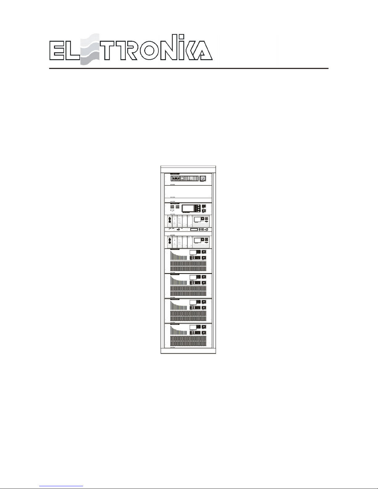
The AUTV/5000LD belongs to the High Power UHF products family of Television Amplifiers fully in solid
state technology.
The AUTV/5000LD series represents the 5kW TV Amplifier operating in the IV/V Band for Common
amplification process (separate amplification available) of the Vision and Sound carriers. This Transmitters
family has been designed to offer to the customer high performances, high reliability and greater simplicity in
their operation and maintenance procedures.
The Vision and Sound signal processing is provided for all TV Standards and all types of Audio applications
(Mono & Dual sound - NICAM) together with colour systems such as PAL - NTSC - SECAM. Thanks to
the amplitude and phase pre-correction circuit, it is possible to cancel the distortions in the output stage, thus
cutting down the operating costs. The RF transposition in the driver is carried out by a synthesizer with various
possibilities of accuracy and stability as well as precision offset locked by internal or external frequency
reference.
The RF amplifier is made up by four RF modules installed in a power rack, the modules are dedicated for the
Vision and Sound carriers common amplification. The amplifiers employ solid state LDMOS technology in
order to obtain wide band, reliability, and high efficiency. Each RF module has a built-in switching-mode
power supply unit, self-protected against overcurrents and overvoltages, as well as overtemperature and
VSWR for RF parameters. The cooling system is fully contained into the transmitter. The control unit provides
full management of the transmitter without the presence of the operator, the system includes a central controller
and several peripheral units installed in each RF module and rack. Controller and peripherals are connected
by a RS485 full-duplex bus.
Power supply output voltages and currents, forward and reflected power of any single power amplifier are
monitorized by central control unit.
In that way there is a single interface point between user and all the transmitter. The operator interface is made
by a high resolution LCD graphic display and a simple keyboard, the menu is very friendly and easy to use.
The Control Unit can be fully controlled in REMOTE mode via link or via modem in RS232 or other interface.
The equipment design allows the soft degradation (RF power loss) for several transistors faults.
AUTV/5000LD
LDMOS - UHF TV SOLID STATE AMPLIFIER

11
TECHNICAL CHARACTERISTICS
RF SECTION
Frequenchy range ............................................................................................................................................ 470 - 860MHz
Output power .......................................................................................................................................................... 5kW PEP
Vision / Sound power ratio...................................................................................... 10/1 single sound - 20/1/0.2 dual sound
Out stage technology .............................................................................................................................Solid State LDMOS
Vision / Sound amplification .................................................................................................................................... Common
Standards ................................................................................................................................................................ G, K, I, M
Sound transmission ..................................................................... FM single sound - Dual sound coding IRT - NICAM 728
Harmonics and suppression emission ..................................................................................... In compliance with CCIR rec.
Intermodulation products from vision and sound ................................................................................................... < = 50dB
Frequency stability ......................................................................................................................... 2,5ppm (option 0,05ppm)
VISION SECTION
Video input............................................................................................................................................. BNC 75W connector
Nominal input level .............................................................................................................................................. 1Vpp ±6dB
Return loss ............................................................................................................................................................... > = 30dB
DC Restoration ........................................................................... Clamped to the blanking level without affecting the burst
White limiter ................................................................................. At 90% picture signal without affecting the chrominance
Transmission characteristics
Sideband spewctrum response ....................................................................................................According to the standard
Amplitude frequency response.................................................................................................... According to the standard
Group delay variation without receiver pre-correction and TV demodulator flat ................................................... < = ±35ns
Non linearity distortion (10 to 75% mod.) ................................................................................................................... < = 5%
Differential gain (10 to 75% mod.) ............................................................................................. .................................. < = 5%
Differential phase (10 to 75% mod.) .............................................................................................................................. < = 5°
Signal to random noise ratio (weighted 0.2 to 5MHz) .............................................................................................. > = 60dB
Blanking level variation ...............................................................................................................................................< = 2%
2T k factor ................................................................................................................................................................... < = 2%
SOUND SECTION
Nominal input level (±50kHz dev.)..................................................................................................................... -10 to +8dBm
Input impedance ............................................................................................................................................ 600W balanced
Pre-emphasis ..................................................................................................................................................................50ms
Transmission characteristics
Amplitude frequency response............................................................................................................ 40 to 15000Hz ±0.5dB
Total harmonic distortion ......................................................................................................................................... < = 0.5%
FM Signal to noise ratio (referred to ±50kHz dev. f = 400Hz) ................................................................. > = 60dB (weighted)
AM Signal to nokise ratio .......................................................................................................... > = 50dB (referred to 100%)
AM Synchronous modulation ................................................................................................... < = 40dB (referred to 100%)
REMOTE CONTROL
Parallel interface ............................................................................................................................. On/Off, Alarms, Interlock
Serial interface ....................................................................................... RS232 or RS485 (Full monitoring and management)

12
GENERAL
Power supply voltage ................................................................................................... 3x380VAC, ±10% (other on request)
Frequency ........................................................................................................................................................ 50-60Hz, ±5%
Temperature operating range .................................................................................................................................. 0 to 45°C
Altitude ............................................................................... Up to 2.500 meters (> = 2.500m with additional cooling system)
Power consumption (cooling system included) .................................................................................< = 12kVA (black level)
Power factor ................................................................................................................................................................ > = 0.9
Cooling .................................................................................................................................................................. Forced air
Dimensions ...................................................................................................................................................... Rack 19-42U
13
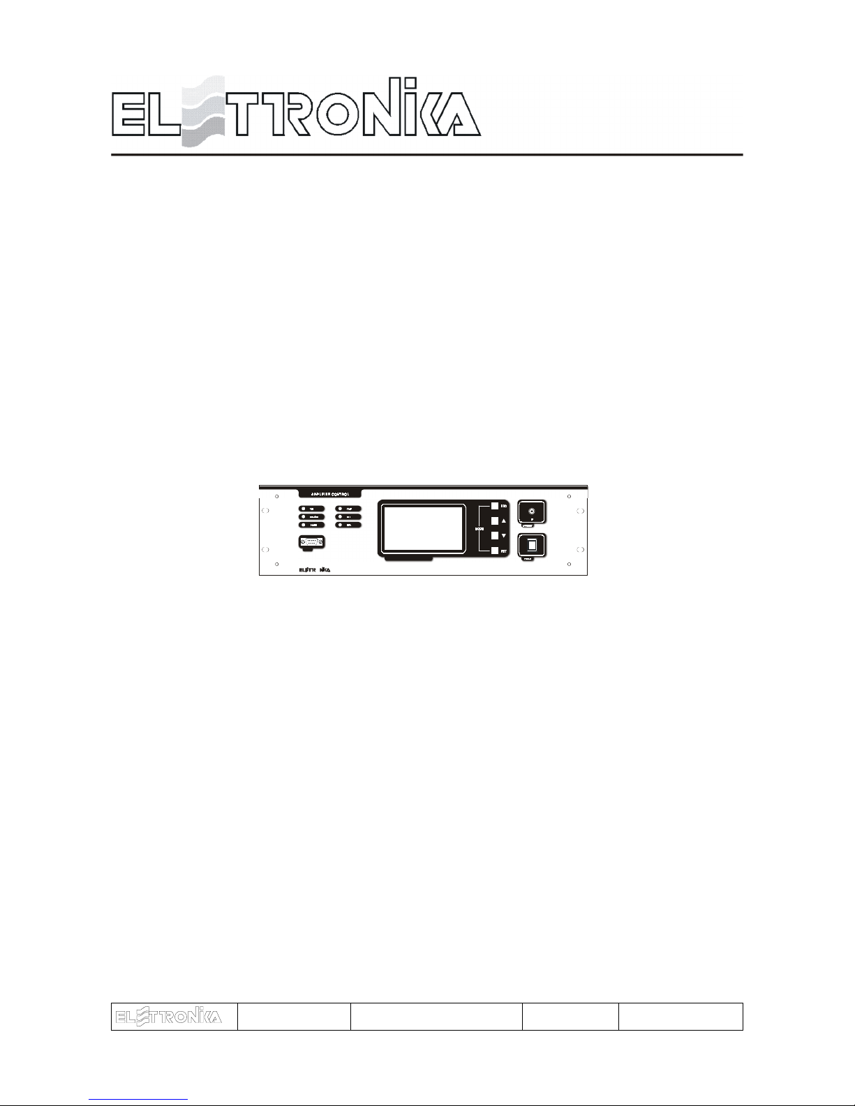
AMPLIFIER CONTROL
O
MICROPROCESSOR CONTROLLED SYST EM
RS232
CODE: APG012C TITLE: AMPLIFIER CONTROL REV: 1 DATE: 10/02/04
14
1.1 CONTROL SYSTEM OVERVIEW
The control system is made up by some Slave boards, which check locally the amplifier modules, and a
Master board to monitor the status of the Slave boards in each module and show on a graphic display all
the checked parameters.
The number of the Slaves changes depending on the output power of the amplifier. The communication
between Master and Slaves is made via RS485 standard. The Master board reads the overall parameters of
the equipment (Forward and Reflected power and Unbalancing), polls (interrogaes in sequence) the local
boards, shows on the display the values requested by the user, indicates alarm conditions, if any, and allows
to change some of the operating parameters of the apparatus. Besides it realizes a serial data interface to an
external system able to analyse the working parameters of the equipment, using the RS232 and RS485
communication protocols.
1.2 FUNCTIONS
At start-up, the display of Amplifier Control module shows an informational message concerning the equipment
and its firmware version.
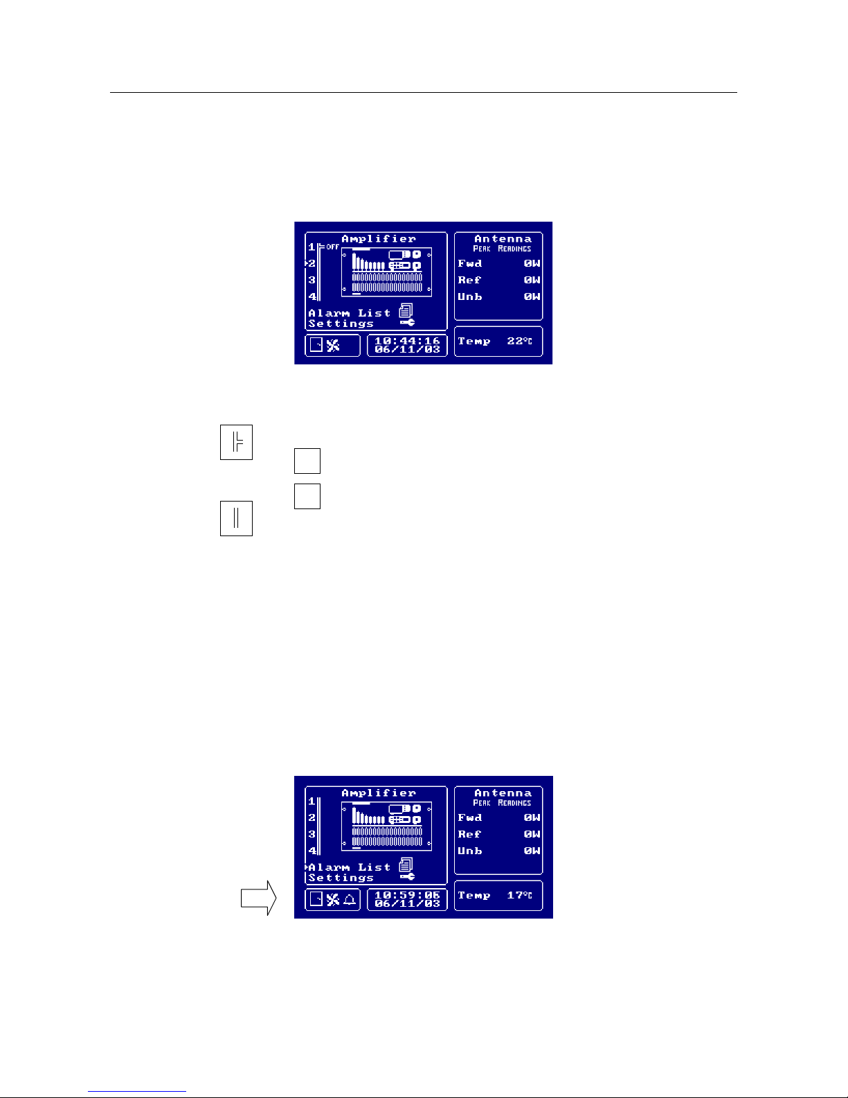
- Main menu
The main menu has: a list of the amplifier modules, the measure of some parameters of the power in antenna,
a window with icons to show the alarm status (Alarm Status Window) and some general information, that is
date, time, temperature inside the module and, for FM equipment, transmission frequency.
The following picture is an exact representation of the main menu screen.
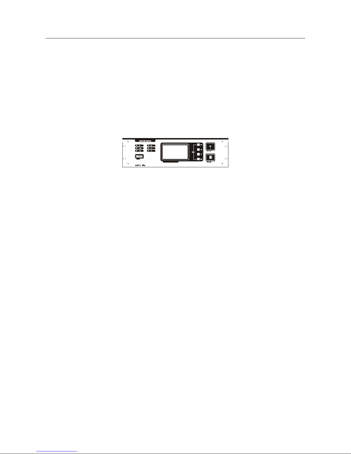
AMPLIFIER CONTROL
O
MICROPROCESSOR CONTROLLED SYSTEM
RS232
15
if the communication with the slave is correct and then
if the communication with the slave is interrupted
ON
if the amplifier module is OFF
OFF
if the amplifier module is ON
In the Amplifier List, next to each module, the following symbols can be found:
The UP and DOWN arrow keys allow to select one of the slave, the alarm list, or a menu allowing to change
some settings of the control module and the apparatus; the RET key is used to confirm the selection.
In the main and slave menu the Alarm Status Window (which position is indicated by an arrow in the picture
below) is shown: the gate symbol displays the status of the INTERLOCK, in case of alarm this icon blinks
and the buzzer ringgs.
The INTERLOCK signal is a control available to the user to manage an ON/OFF sensor.
When the relevant PIN is grounded, the Master board does not signal any alarm, as soon as the PIN is left
floating, an alarm is detected; the rotating screw symbol shows that the FANS work normally; in case of alarm
this icon blinks and the buzzer rings; the bell symbol appears in case of alarm detected by the control module
or the amplifier. It blinks if the alarm condition is terminated and the alarm itself can be displayed in the Alarm
List.
If one of the parameters of a Slave or any of the ones directly checked by the Master is alarmed, the general
 Loading...