

Elettronika AUTV/2000LD User Manual

AUTV/2000LD
LDMOS - UHF TV Amplifier
Users manual
CODE: APT088A TITLE: AUTV/2000LD REV: 0 DATE: 17/02/03

SS 96 Km 113
70027 Palo del Colle (Ba) IT ALY
Tel. +39 (0)80 626755
Fax +39 (0)80 629262
E-mail: elettronika@elettronika.it
Web siste: http://www.elettronika.it
Registration number: IT-17686
Registration number: IT-24436

Index
Index................................................................................................................................... 3
Warning .............................................................................................................................. 5
Warranty............................................................................................................................. 6
Introduction ....................................................................................................................... 7
Content of the manual....................................................................................................... 7
Treatment of electrical shock ........................................................................................... 9
First-aid .........................................................................................................................10
T reatment of electrical burns.......................................................................................... 10
Note ...............................................................................................................................10
APT088A AUTV/2000LD .................................................................................................. 11
Description .................................................................................................................... 12
Technical characteristics ............................................................................................... 13
APT088A AUTV/2000LD - Component list ....................................................................... 15
APG012B AMPLIFIER CONTROL ................................................................................... 17
1.1 Functions ................................................................................................................. 18
1.2 Programming mode................................................................................................. 20
1.3 Setting...................................................................................................................... 20
- FWD Power calibration............................................................................................. 20
- REF Power calibration.............................................................................................. 21
- UNB Calibration.......................................................................................................21
1.4 Remote control ........................................................................................................ 21
1.5 RS232 and RS485 Pin tables.................................................................................. 22
1.6 Telemeasuring pins table ........................................................................................ 23
1.7 Other tables.............................................................................................................. 24
Front panel .................................................................................................................... 26
Rear panel..................................................................................................................... 27
APG012B AMPLIFIER CONTROL - Component list ...................................................... 29
SCH0109BR0 (Master board) ....................................................................................... 31
SCH0110BR0 (Analog input for master board).............................................................. 39
SCH0152AR0 (230VAC Switching board)..................................................................... 42
SCH0153AR0 (In/Out digital for APG012B)................................................................... 45
S-50-24 (Switching power supply) .................................................................................. 48
APT084ASF AUTV/1000LD ............................................................................................. 53
Section 1 - Information .................................................................................................... 55
1.1 Description............................................................................................................... 56

1.2 Technical characteristics.......................................................................................... 57
Section 2 - Installation..................................................................................................... 59
2.1 Operating environment ............................................................................................60
2.2 Preliminary operations............................................................................................. 60
2.3 Telemeasuring socket connections ......................................................................... 61
2.4 RS232 and RS485 socket connections ................................................................... 61
2.5 SCH0005AR1 Calibration procedure ...................................................................... 62
- Power supply voltages and currents calibration........................................................ 62
- Temperature calibration ........................................................................................... 63
- Forward power calibration......................................................................................... 63
- Reflected power calibration ...................................................................................... 63
2.6 Preventive maintenance .......................................................................................... 64
Front panel .................................................................................................................... 65
Rear panel..................................................................................................................... 66
Section 3 - Diagram ......................................................................................................... 67
Cable diagrams ............................................................................................................. 68
APT084ASF AUTV/1000LD - Component list .................................................................. 71
SCH0005AR1 (Protection board) .................................................................................. 73
SCH0004AR0 (Relay board)......................................................................................... 82
PN502 (Display board) .................................................................................................. 87
MTF0050AR0 (1kW LDMOS Power module) ................................................................ 90
SP500-27/48 (Switching power supply).......................................................................... 94
06641 (UHF Band-pass filter) ...................................................................................... 102

5
WARNING
The apparatus described in this manual has been designed and manufactured with devices to safeguard the users. In any case it is recommended that during any operation of installation, maintenance,
miscellaneous interventions and calibrations requiring the apparatus to be switched on,
THE USER TAKES ALL THE
PRECAUTIONS AGAINST INCIDENTS
It is required to use the proper clothes and protection gloves in order to prevent damages from incidental contacts with high-voltage parts.
The manufacturer declines every responsibility in case the recommendations above are not followed.
IMPORTANT
The component lists attached to the relevant electrical diagrams indicate for each item the reference,
the description and the type normally used.
The Elettronika S.r.l. though reserves the right to use or supply as spare parts components with
equivalent characteristics but of a different type, assuring anyway the optimal work of the apparatus
in accordance with the specifications.
The enclosed monographs are solely owned by Elettronika S.r.l.
The use of anything enclosed in this technical manual without explicit authorization given by Elettronika
S.r.l. will be prosecuted by the law.
The data and technical characteristics of the apparatus described in this manual are not compelling for
the manufacturer.
The Elettronika S.r.l. reserves the right to make, without previous notice, modifications or updates in
order to improve the quality of the product.
The general conditions of supply and sale are described in the contracts.
The delivery time are in accordance with the products and quantities ordered.

6
Summary of warranty
We, ELETTRONIKA S.r.l., SS096 Km 113 Z.I. PALO DEL COLLE (BA) ITALY, warrant to the ORIGINAL PURCHASER of a NEW product, for a
period of one (1) year from the date of purchase by the original purchaser (the “warranty period”) that the new ELETTRONIKA product is free of defects
in materials and workmanship and will meet or exceed all advertised specifications for such a product. This warranty does not extend to any subsequent
purchaser or user, and automatically terminates upon sale or other disposition of our product.
Items excluded from this ELETTRONIKA warranty
We are not responsible for product failure caused by misuse, accident, or neglect. This warranty does not extend to any product on which the serial
number has been defaced, altered, or removed. It does not cover damage to loads or any other products or accessories resulting from ELETTRONIKA
product failure. It does not cover defects or damage caused by use of unauthorized modificstions, accessories, parts, or service.
What we will do
We will remedy any defect, in material or workmanship (except as excluded), in our sole discretion, by repair, replacement, or refund. If a refund is
elected, then you must make the defective or malfunctioning component available to us free and clear of all liens or other encumbrances. The refund will
be equal to the actual purchase price, not including interest, insurance, closing costs, and other finance charges less a reasonable depreciation on the
product from the date of original purchase. Warranty work can only be performed at our authorized service centers or at our factory. Expenses in
remedying the defect will be borne by ELETTRONIKA, including one-way surface freight shipping costs within the United States. (Purchaser must bear
the expense of shipping the product between any foreign country and the port of entry in the United States and all taxes, duties, and other custom’s fee(s)
for such foreign shipments).
How to obtain warranty service
You must notify us of your need for warranty service not later than ninety (90) days after the expiration of the warranty period. We will give you an
authorization to return the product for service. All components must be shipped in a factory pack or equivalent which, if needed, may
Desclaimer of consequential and incidental damages
You are not entitled to recover from us any consequential or incidental damages resulting from any defect in our product. This includes any damage
to another product or products resulting from such a defect.
Warranty alterations
No person has the authority to enlarge, or modify this warranty. The warranty is not extended by the lenght of time for which you are deprived of
the use of the product. Repairs and replacement parts are provided under the terms of this warranty shall carry only the unexpired portion of this
warranty.
Design changes
We reserve the right to change the design of any product from time to time without notice and with no obligation to make corresponding changes in
products previously manufactured.
Legal remedies of purchaser
There is no warranty which extends beyond the terms hereof. This written warranty is given in lieu of any oral or implied warranties not contained
herein. We disclaim all implied warranties, including without limitation any warranties of merchantability or fitness for a particular purpose. No action
to enforce this warranty shall be commenced later than ninety (90) days after expiration of the warranty period.
Warranty for electronic tubes
The warranty applied for electronic tubes is the one given by the manufacturer of the tube. In the event that the product shows anomalies within the
deadline of the validity of the warranty given by the manufacturer of the product itself, the buyer will have to return it to the seller with the needed
documents and the written description of the defect. The seller will ship the broken tube to the manufacturer in order to effect the necessary technical
tests to find out the cause of the anomaly. Meanwhile the buyer of the tube who needs to use, and as such to replace immediately the product, will have
to buy a new one and provide to the relevant payment, further to the issuing by the seller of a regular commercial invoice. After the adequate tests made
by the manufacturer, should the result be positive, that is confirm the defect in manufacturing, the seller will issue a regular credit note in the name of
the buyer and return the amount paid. Should the result be negative, that is detect a negligence in the installation or use by the buyer, he will have no
right against the seller.
Warranty

7
INTRODUCTION
The apparatus described in this manual is the latest of this series, offering high performances, remarkable reliability and a wide range of characteristics, it all at a low cost.
Its is easy to install and use. It only takes to follow the installation procedure as shown in this manual:
after having removed all from the package, you only have to follow step by step the description in the
various sections.
Before starting to use the apparatus, remember to:
read carefully the general safety information contained in this section;
follow the instructions for the installation and set up of the apparatus;
read all the remaining sections of this manual in order to know well the apparatus and learn
how to obtain the best of its characteristics.
CONTENTS OF THE MANUAL
The chapter composing this manual contain all the information concerning the use of the apparatus.
For more information refer to ELETTRONIKA S.r.l.
This manual is made up of different chapters, each made up of various sections. Each individual
chapter represents a single apparatus composing the whole station.

8
WARNING!
The currents and voltages in this equipment are dangerous!
Personnel must at all times observe safety regulation!
This manual is intended as a general guide for trained and qualified personnel who are aware of the
dangers inherent in handling potentially hazaedous electrical and electronic circuits.
It is not intended to contain a complete statement of all safety precautions which should be observed by
personnel in using this or other electronic equipment.
The installation, operation, maintenance and service of this equipment involves risks both to personnel
and equipment, and must be performed only by qualified personnel exercising due care.
Elettronika S.r .l. shall not be responsible for injury or damage resulting from improper procedures or
from the use of improperly trained or inexperienced personnel performing such tasks.
During installation and operation of this equipment, local building codes and fire protection standards
must be observed.
W ARNING!
Always disconnect power before opening covers,
doors, enclosures, gates, panels or shields.
Always use grounding nsticks and short out high
voltage points before servicing. Never make
internal adjustments, perform maintenance or
service when alone or when fatigued.
Do not remove, short-circuit or tamper with interlock switches on access covers, doors, enclosures,
gates, panels or shields.
Keep away from live circuits, know your equipment and don’t take chances.
W ARNING!
In case of emergency ensure that power has been disconnected.

9
A - AIRWA Y
If unconscious, open airway lift up neck, push
forehead back, clear out mouth if necessary,
observe for breathing.
Treatment of electrical shock
1) If victim is not responsive follow the A, B, C’s of basic life support.
PLACE VICTIM FLA T ON HIS BACK ON A HARD SURF ACE
B - BREA THING
If not breathing, begin artificial breathing. Tilt
head, pinch nostrils, make airttght seal, 4 quick
full breaths. Remember mouth to mouth resuscita-
tion must be commenced as soon as possible.
C - CIRCULA TION
Check carotid pulse. If pulse
absent, begin artificial circulation.
Approx. 80sec.: 1 rescuer, 15 compressions, 2 quick breaths.
Approx. 60sec.: 2 rescuers, 5 compressions, 1 breath.
NOTE: DO NOT INTERRUPT RHYTHM OF COMPRESSIONS WHEN
SECOND PERSON IS GIVING BREA TH.
Call for medical assistance as soon as possible.

10
2) If victim is responsive:
- keep them warm;
- keep them as quiet as possible;
- loosen their clothing (a reclining position is recommended).
FIRST-AID
Personnel engaged in the installation, operation, maintenance or servicing of this equipment are urged
to become familiar with first-aid theory and practices. The following information is not intended to be
a complete first-aid procedure, it is brief and is only to be used as a reference. It is the duty of all
personnel using the equipment to be prepared to give adequate Emergency First Aid and thereby prevent avoidable loss of life.
TREA TMENT OF ELECTRICAL BURNS
1) Extensive burned and broken skin.
- Cover area with clean sheet or cloth (cleansed available cloth article);
- do not break blisters, remove tissure, remove adhered particles of clothing, or apply any salve or
ointment;
- treat victim for shock as required;
- arrange transportation to a hospital as quickly as possible;
- if arms or legs are effected keep them elevated.
NOTE
If medical help will not be available within an hour and the victim is conscious and not vomiting, give
him a weak solution of salt and soda: 1 level teaspoonful of salt and 1/2 level teaspoonful of baking
soda to each quart of water (neither hot or cold).
Allow victim to sip slowly about 4 ounces (half a glass) over a period of 15 minutes.
Discontinue fluid if vomiting occurs (do not give alcohol).
2) Less severe burns - (1st & 2nd degree).
- Apply cool (not ice cold) compresses using the cleansed available cloth article;
- do not break blisters, remove tissue, remove adhered particles of clothing, or apply salve or ointment;
- apply clean dry dressing if necessary;
- treat victim for shock as required;
- arrange transportation to a hospital as qickly as possible;
- if arms or legs are affected keep them elevated.
11
LDMOS - UHF AMPLIFIER
AUTV/2000LD
User’s manual
O
MICROPROCESSOR CONTROLLED SYSTEM
RS232
POWER

12
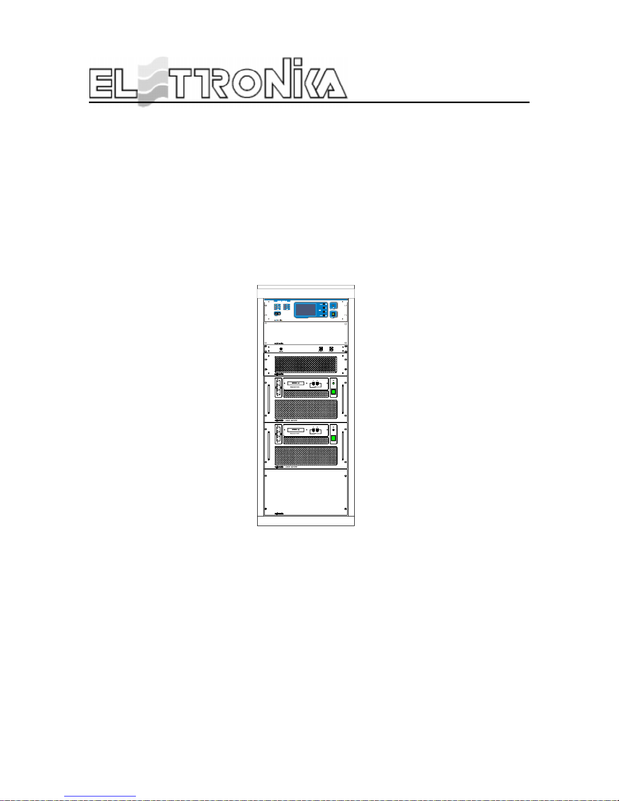
AUTV/2000LD
LDMOS - UHF TV AMPLIFIER
DESCRIPTION
The AUTV/2000LD is a TV amplifier that can be used in the IV/V Bd UHF . Tutti gli stadi di amplificazione
utilizzano componenti con tecnologia LDMOS, ottenendo eccellenti prestazioni in termini di guadagno e
soprattutto di linearità.
Thanks to the high-quality components used and the strong structure it can be used even in the most hostile
environments with the minimum maintenance.
It is composed by two amplifiers AUTV/1000LD coupled by means of 3dB/90° hybrid couplers ensuring an
high insulation between the apparatuses and a very good input return loss.
The amplifier AUTV/2000LD has been designed using advanced technologies made for broadcasting applications. All of its components have been tested with thermic shocks in order to obtain a very high reliability
and an high MTBF .
A microprocessor control unit controls the apparatus, checking the thermic, electric and RF parameters,
intervening in case of problems and showing the whole functioning status on a large LCD display .
The purity of the spectrum is ensured by a band-pass filter which removes all the out-of-band spurious
emissions far beyond the level required by the regulations.
The transmitter is provided with linearity pre-corrector to compensate the distortions of the final stage.

13
TECHNICAL CHARACTERISTICS
RF SECTION
Frequency range 470 - 860MHz
Vision/Sound amp. Common
Output power 2000W peack sync.
Output power control Automatic or manual (switch-selected)
Output frequency stability 2,5ppm (option 0,05ppm)
Out stage technology LDMOS Solid State
I.M.D. < -54dB(with IF-Precorrector)
Spurious and harmonics level < -60dB
RF Output impedance 50 Ω
RF Output connector EIA 7/8”
Intermediate frequency 38.9 or 45.75MHz on request
SOUND SECTION
Input level 1Vpp (adj.)
Input impedance 600Ω Balanced
Input connector Twinax
Pre-emphasis 50µs
Frequency response 30Hz - 15kHz, ±0.5dB
T otal harmonic distortion < -0.5%
FM Signal noise ratio > -68dB
(referred to +/-50kHz dev. f = 400Hz) > -60dB (unweighted)
VIDEO SECTION
Input level 1Vpp
Input impedance 75Ω
Return loss 26dB
Differential gain < 5%
Differential phase < 5°
Group delay ±40ns
Input connector BNC Female
Sideband spectrum response According to the standard
Amplitude frequency response According to the standard
GENERAL
Power supply 230V ac, ±10%, 50/60Hz
400V ac 3P+N (on request)
RS232 Socket DB9 Connector (on Amplifier Control)
T elemeasuring socket DB25 Connector (on Amplifier Control)
AGC Socket DB9 Connector (on Amplifier Control)
I2C BUS Socket 2xDB9 Connector (on Amplifier Control)

14
Ambient temperature -5° to +45°C
Humidity 20% - 90%
Cabinet Rack 19”-28U
Dimensions 560x1000x1460mm
W eight 300kg
PROTEC. THR. (AUTV/1000LD)
FWD Power 1200W
REF Power 100W
T emperature 70°C
IDC
DRIVER
12A
IDC
AMPLIFIER
20A
VDC
DRIVER
31V
VDC
AMPLIFIER
33V

15
Part Name Code Description Qt y
APT084ASF CASSETTO AMPLIF . UHF 1kW LDMOS 220V 2
APG016A CARICO FITTIZIO 50Ω 1kW UHF 1
06641 BAND P ASS FIL TER UHF 1kW CL4NL22 7/16 1
APG012B CASSETTO CONTROLLO AMPLIFICA TORE 1
06816A ACCOP. 3dB IBRIDO 2.5kW UHF m/f 1
MTG0045AR0 ACCOP . DIR. CON PRELIEVO -50/-40dB 1
CMS6006 CA VO 1/2” DA 1mt CONN. 7/16(M) BN203391 1
CMS6007 CA VO 1/2” DA 2mt CONN. 7/16(M) BN203388 1
06811B ACCOP . IBRIDO 3dB 300W CON CARICO 20W 1
02408 SP 10/12 90° 7/16 M+F 90° 1
08510 CABLE RG213 50Ω 3,20
02201 CONNET . Nm x RG213 GE 15015 C4 5
02230 R161270000 (N flg. RG213) 1
08504 CABLE RG58 50Ω 5,50
02015 R141082161 BNC A CRIMP . x RG58 5
02502 J01150A0041 SMA x RG58/c 1
02576 TAPPO RIV. CON HP 2800 2
02205 NM 90° x RG58 CRIMP ARE GE 15142 D/60 2
08503 CABLE RG303 50Ω 0,20
07625A CONDENSAT ORE 3uF CON FILI 1
07620 GRIGLIA AL T A G025001-00-01 1
07625 VENTOLA EBM A2E250-AM06-13 1
07622 BOCCAGLIO BOCC. 250 AL 1
02871 CALOTTE PER DB9 cod. 525-2620 2
02791 CONNETTORE DB9M x CA VO 525-2600 2
V0762 TAPPI NERI O 15.9 PLASTICA DP-625 1
M0800 GUIDA DIN PROFILA T A OMEGA Z002 SEM 3
V0958 ACCESSORIO GUIDA DIN ELECO E205 6
05597 POST . x RACK 28U VER CON0099R0 1
CON0057 CON0057R1 CHIUS. SUP . RACK PER AUTV 2kW 1
Z0500 T A V . 1081/E GUIDA RACK 3000W P .2328 ZN 1 0
DET0462 DET0462R0 BARRA x RACK SOSTEGNO PCA V ZN 2
DET0434 DET0434R2 ANCORAGGIO FLANG. 7/8 CON RACK 1
DET0391 DET0391R0 BARRA FISS. ACC. INP AUDIO 5kW 1
DET0538 DET0538R0 PIASTRA ANCOR. ACC. DIR. FIL. 2kW 1
DET0537 DET0537R0 PIASTRA ANCOR. ACC. DIR. FIL. 2kW 1
DET0536 DET0536R0 ANGOLARE FISS. FIL TRO 2kW COMT . 2
DET0535 DET0535R0 BARRA FISS. FIL TRO 2kW COMT . 2
V0962 MORSETTIERA/GIUNZIONE ELECO E806 3
09627 CASSETTO TRASF . SEP ARA T . DI RETE 8kVA 1
07627B SPINA PROT .B.T. 32A 2P+T 220V GW60015 1
07627C PRESA VOL. 32A 2PT 220V GW62015 1
R0154 RACK 28U 565x1000 1
P AN0017 PAN0017R0 P ANNELLO AV ANTI DIETRO 1
02571 CARICO BNC 1/2W 50Ω 2
Component list APT088A - AUTV/2000LD

16
This page is intentionally blank
17
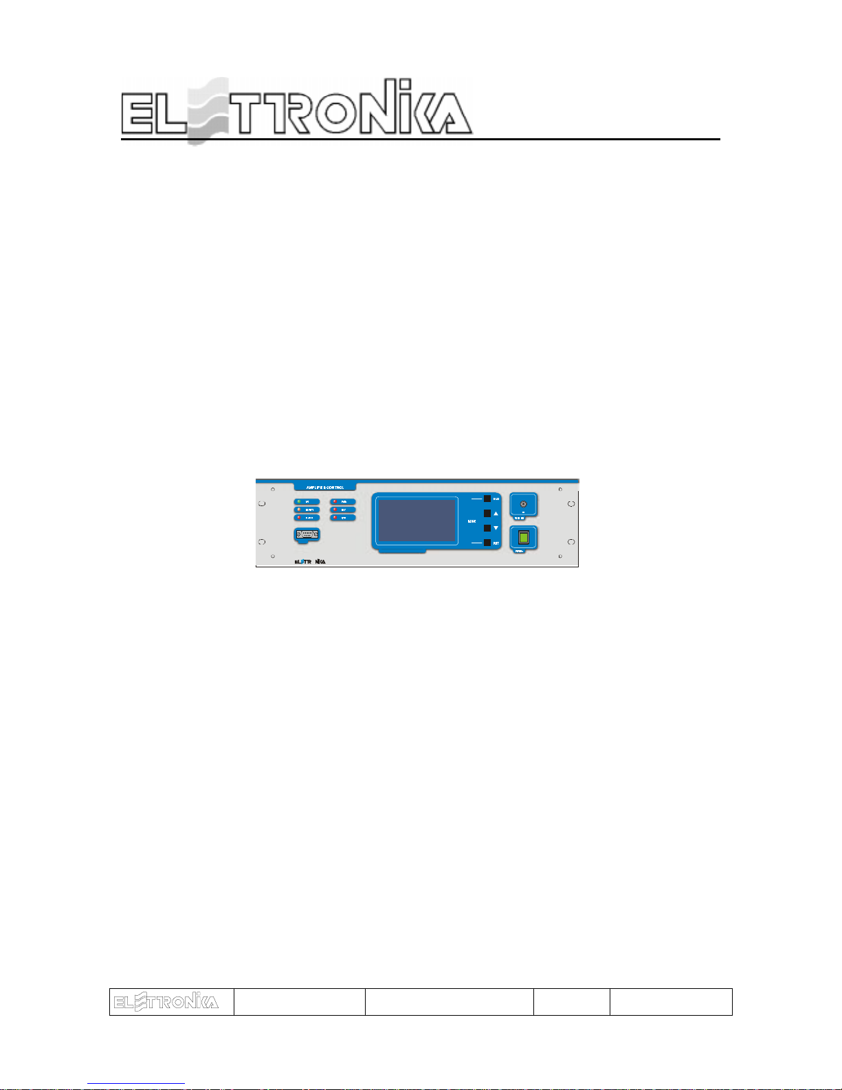
AMPLIFIER CONTROL
O
MICROPR OCE SSOR CON TROLLE D SYSTEM
RS232
POW ER
CODE: APG012B TITLE: AMPLIFIER CONTROL REV: 0 DATE: 25/11/02
18
1.1 FUNCTIONS
The control system is made up by some “Slave” boards, which check locally the amplifier modules,
and a “Master” board to monitor the status of the Slave boards in each module and show on a graphic
display all the checked parameters. The number of the Slaves changes depending on the output power of
the amplifier. The communication between Master and Slaves is made via I2Cbus standard. The Master
board reads the overall parameters of the equipment (forward and reflected power and unbalancing),
polls (interrogates in sequence) the local boards, shows on the display the values requested by the user
and indicates alarm conditions, if any. Besides it realizes a serial data interface to an external system
able to analyse the working parameters of the equipment, using the RS232 and RS485 communication
protocols.
At start-up, the display of the Amplifier Control shows an informational message concerning the equipment and the firmware version.
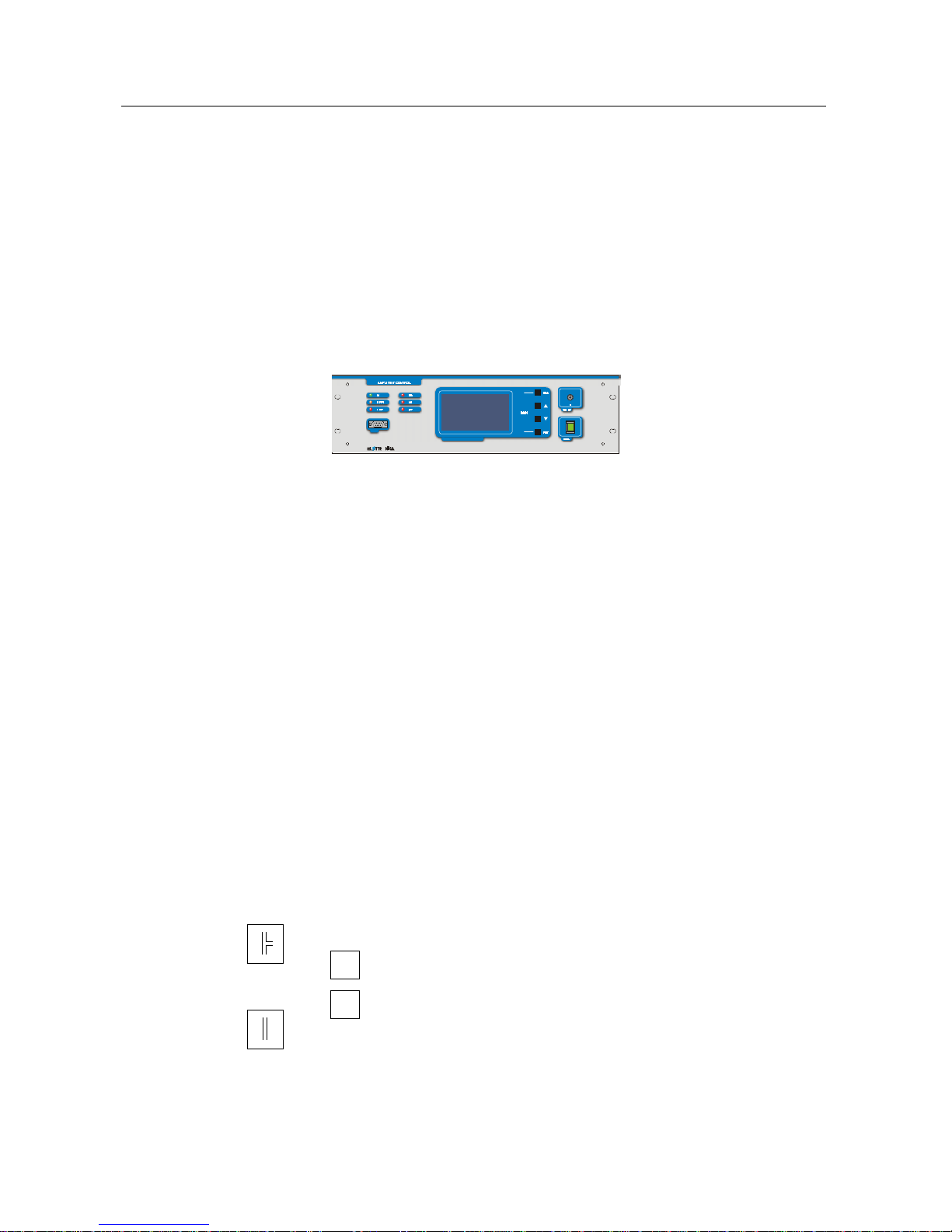
The main menu has: a list of the amplifier modules, the measure of some parameters of the powers in antenna,
a window with icons to show the alarm status and some general information, that is date, time, temperature
inside the module and, for FM equipment, transmission frequency .
In the Amplifier List, next to each module, you can find the following symbols:
AMPLIFIER CONTROL
if the communication with the slave is correct and then
if the communication with the slave is interrupted
ON
if the amplifier module is OFF
OFF
if the amplifier module is ON
O
MICROPR OCESSOR CO NTROLLED SYSTEM
RS232
POWER
 Loading...