

Elettronica Santerno SINUS/ISD 200 S - 2.2, SINUS/ISD 200 T - 2.2, SINUS/ISD 400 T - 0.75, SINUS/ISD 400 T - 1.5, SINUS/ISD 400 T - 2.2 User Manual
...
USER MANUAL
•
•
•
•
•
•• 15P0082B8 ••
SINUS/ISD 0.75÷÷4 kW
VECTORIAL SENSORLESS INVERTER
VERS. 4.x R. 0.1
(EXTENDED MANUAL) UPD. 15/03/99
This manual is integrant and essential to the product. Carefully read the instructions contained herein as they
provide important hints for use and maintenance safety.
This device is to be used only for the purposes it has been designed to. Other uses should be considered
improper and dangerous. The manufacturer is not responsible for possible damages caused by improper,
erroneous and irrational uses.
• Elettronica Santerno is responsible for the device in its original setting.
Any changes to the structure or operating cycle of the device must be performed or authorized by the
Engineering Department of Elettronica Santerno.
• Elettronica Santerno assumes no responsibility for the consequences resulting by the use of non original spare-
parts.
Elettronica Santerno reserves the right to make any technical changes to this manual and to the device without
prior notice. If printing errors or similar are detected, the corrections will be included in the new releases of the
manual.
• Elettronica Santerno is responsible for the information contained in the original version of the Italian manual.
The information contained herein is the property of Elettronica Santerno and cannot be reproduced. Elettronica
Santerno enforces its rights on the drawings and catalogues according to the law.
English
Elettronica Santerno Elettronica Santerno S.p.A.S.p.A.
Via G. Di Vittorio, 3 - 40020 Casalfiumanese (Bo) Italy
Tel. +39 542 668611 - Fax +39 542 666632
After Sales Service Tel. +39 542 668610 - Fax +39 542 666778
Sales Office Tel. +39 51 6010231 - Fax +39 51 534403

15P0082B8
USER MANUAL
SINUS/ISD
IMPORTANT SAFETY WARNINGSIMPORTANT SAFETY WARNINGS
ATTENTION!!: READ THIS BEFORE INSTALLING THE INVERTERATTENTION!!: READ THIS BEFORE INSTALLING THE INVERTER
THIS MANUAL IS FOR THE FOLLOWING USERSTHIS MANUAL IS FOR THE FOLLOWING USERS
This manual must be made available to all the staff involved in calibrating, installing and performing maintenance
work on the equipment described here, or involved in other related operations. The information provided here
lays down the safety requirements to be complied with while using the inverter in order to allow the user to make
it work in the best way.
USERSUSERS
Installation, commissioning and maintenance of this equipment must be performed only by qualified and
technically competent personnel, familiar with the safety regulations and procedures to be complied with, and
aware of the hazards the use of this equipment implies.
HAZARDSHAZARDS
Use of this equipment can imply serious hazards due to revolving bodies and high voltages. This equipment
contains condensers, which stay charged up to several minutes after the power supply has been cut off. Before
tuning on the inverter, make sure that the power supply on L1, L2 and L3 has been cut off, then wait at least 3
minutes in order to allow the condensers to go down to a voltage level which is not dangerous (<50 V) at the DC
terminals (DC+ and DC-).
Should you replace a inverter inside the system, and before starting operations again, it is absolutely necessary
to restore all pre-set parameter values properly.
ATTENTION!!:ATTENTION!!: Non-compliance with these rules is hazardous for the personal safety of the operator.
ATTENTION!!:ATTENTION!!: The metal parts of the equipment may reach 90°C.
FIELDS OF USEFIELDS OF USE
The equipment described below has been designed for the industrial control of standard AC induction motors, or
AC asynchronous machines.
RISKS CONNECTED WITH THE APPLICATIONSRISKS CONNECTED WITH THE APPLICATIONS
The technical specifications, logical processes and circuit diagrams described inside this manual are of a general
nature and might require adaptation to specific applicational needs
HAZARDOUS SITUATIONSHAZARDOUS SITUATIONS
In a breakdown condition, a blackout or unexpected working conditions, the equipment may not operate as
described in this manual. Especially:
⇒ The speed of the motor may not be under control.
⇒ The direction of rotation of the motor may not be under control.
⇒ The motor may be live.
IN EVERY SITUATIONIN EVERY SITUATION
The user must prepare a protection system and/or additional safety systems so as to prevent accident and
shock risks.
HOW TO USE THIS MANUALHOW TO USE THIS MANUAL
This manual contains the basic instructions needed to install, commission and operate the SINUS/ISD inverter.
This information is presented in a logical sequence for starting the inverter up.
TABLE OF CONTENTS

SINUS/ISD
ACCESSING THE SOFTWARE
To obtain the access to the menus proceed as it follows:
- select the parameter password of OPERATOR menu
- insert the value composed of four numbers reported in the label:
15P0082B8
USER MANUAL
- To insert the password press M to enable the cursor, modify with until the right value, press E ,
the message “password unlocked” is displayed: now is impossible to access to the parameter “view level”
inside the menu Menus and select, according to requirements of programming, the level basic or advanced.
Refer to Chapter 5 and 6 for management of password and for further information about the programming of the
inverter.
If you want to restore the set of parameters “basic” proceed to a re-load of values that you can withdraw from
Operator Station (see Subchapter 5.4.7.4).
5
6
TABLE OF CONTENTS

15P0082B8
USER MANUAL
SINUS/ISD
TABLE OF CONTENTSTABLE OF CONTENTS
1.01.0 GETTING STARTEDGETTING STARTED
1.11.1 INTRODUCTIONINTRODUCTION 1 - 1/2
1.21.2 EQUIPMENT INSPECTIONEQUIPMENT INSPECTION 1 - 1/2
1.31.3 ABOUT THIS MANUALABOUT THIS MANUAL 1 - 2/2
1.3.1 INITIAL STEP 1 - 2/2
1.3.2 HOW THE MANUAL IS ORGANIZED 1 - 2/2
1.3.2.1 Application Block Diagram 1 - 2/2
1.3.2.2 Information for Users without an Operator Station 1 - 2/2
2.02.0 AN OVERVIEW OF THE INVERTERAN OVERVIEW OF THE INVERTER
2.12.1 COMPONENT IDENTIFICATIONCOMPONENT IDENTIFICATION 2 - 1/4
2.22.2 CONTROL FEATURESCONTROL FEATURES 2 - 2/4
2.32.3 PRODUCT-RELATED DEFAULT VALUESPRODUCT-RELATED DEFAULT VALUES 2 - 3/4
2.3.1 LANGUAGE DEPENDANT DEFAULTS 2 - 3/4
2.3.2 AC SUPPLY VOLTAGE AND POWER RATING DEPENDANT DEFAULTS 2 - 3/4
2.42.4 FUNCTIONAL OVERVIEWFUNCTIONAL OVERVIEW 2 - 4/4
2.4.1 FILTER BOARD 2 - 4/4
2.4.2 POWER BOARD 2 - 4/4
2.4.3 CONTROL BOARD 2 - 4/4
2.4.3.1 Processor 2 - 4/4
2.4.3.2 Technology Box Interface 2 - 4/4
2.4.3.3 Operator Station Interface 2 - 4/4
3.03.0 INSTALLING THE INVERTERINSTALLING THE INVERTER
3.13.1 REQUIREMENTS FOR EMC COMPLIANCEREQUIREMENTS FOR EMC COMPLIANCE 3 - 1/14
3.1.1 MINIMISING RADIATED EMISSIONS 3 - 1/14
3.1.2 EARTHING REQUIREMENTS 3 - 1/14
3.1.2.1 Protective Earth (PE) Connections 3 - 1/14
3.1.2.2 EMC Earth Connections 3 - 1/14
3.1.3 CABLING REQUIREMENTS 3 - 2/14
3.1.3.1 Planning Cable Runs 3 - 2/14
3.1.3.2 Increasing Motor Cable Lenght 3 - 2/14
3.1.4 EMC INSTALLATION OPTIONS 3 - 3/14
3.1.4.1 Screening & Earthing (cubicle mounted, class B) 3 - 3/14
3.1.4.2 Start Point Earthing 3 - 4/14
3.1.4.3 Sensitive Equipement 3 - 5/14
3.23.2 MECHANICAL INSTALLATIONMECHANICAL INSTALLATION 3 - 6/14
3.2.1 MOUNTING THE INVERTER 3 - 6/14
3.2.2 MINIMUM AIR CLEARANCES 3 - 7/14
3.2.2.1 Ventilation 3 - 7/14
3.2.2.2 Air Clearance for an IP20 Product/Application 3 - 7/14
3.33.3 DYNAMIC BRAKINGDYNAMIC BRAKING 3 - 8/14
3.3.1 INTRODUCTION 3 - 8/14
3.3.2 BRAKE RESISTOR SELECTION 3 - 8/14
3.3.3 SPECIFICATION OF THE DYNAMIC BRAKING SWITCH 3 - 9/14
3.3.4 SPECIFICATION AND OVERALL DIMENSIONS OF THE BRAKING RESISTORS 3 - 9/14
3.43.4 ELECTRICAL INSTALLATIONELECTRICAL INSTALLATION 3 - 10/14
3.4.1 WIRING THE INVERTER 3 - 10/14
3.4.1.1 Cable Grand Requirements 3 - 11/14
3.4.1.2 Earth Connections 3 - 11/14
3.4.1.3 Power Wiring Connections 3 - 11/14
3.4.1.4 Control Wiring Connections 3 - 12/14
3.4.2 OPTIONAL EQUIPMENT INSTALLATION DETAILS 3 - 13/14
3.4.2.1 EMC Filters 3 - 13/14
3.4.2.2 Line Chokes (input) 3 - 13/14
3.4.2.3 Motor Chokes (output) 3 - 13/14
3.4.2.4 Output Contactors 3 - 13/14
3.4.2.5 Earth Fault Monitoring Systems 3 - 14/14
TABLE OF CONTENTS

SINUS/ISD
15P0082B8
USER MANUAL
4.04.0 OPERATING THE INVERTEROPERATING THE INVERTER
4.14.1 PRE-OPERATION CHECKSPRE-OPERATION CHECKS 4 - 1/14
4.24.2 CONTROL PHILOSOFYCONTROL PHILOSOFY 4 - 2/14
4.34.3 START/STOP AND SPEED CONTROLSTART/STOP AND SPEED CONTROL 4 - 2/14
4.3.1 SELECTING LOCAL OR REMOTE CONTROL 4 - 3/14
4.44.4 START-UP ROUTINESSTART-UP ROUTINES 4 - 4/14
4.4.1 REMOTE CONTROL USING CONTROL TERMINALS 4 - 4/14
4.4.4.1 Reading the Status LEDs 4 - 4/14
4.4.2 LOCAL CONTROL USING THE OPERATOR STATION 4 - 5/14
4.54.5 SETTING-UP THE INVERTERSETTING-UP THE INVERTER 4 - 5/14
4.5.1 QUICK SET-UP AS AN OPEN-LOOP INVERTER (V/F FLUXING) 4 - 5/14
4.5.2 SET-UP USING THE SENSORLESS VECTOR FLUXING MODE 4 - 6/14
4.5.3 THE AUTOTUNE FEATURES 4 - 6/14
4.5.4 MANUAL TUNING 4 - 7/14
4.5.4.1 Tuning using the Motor Equivalent Circuit 4 - 7/14
4.64.6 THE START/STOP MODE EXPLAINEDTHE START/STOP MODE EXPLAINED 4 - 9/14
4.74.7 STARTING AND STOPPING METHODSSTARTING AND STOPPING METHODS 4 - 10/14
4.7.1 NORMAL STOPPING METHODS 4 - 10/14
4.7.1.1 Ramp to Stop 4 - 10/14
4.7.1.2 Coast to Stop 4 - 11/14
4.7.2 ADVANCED STOPPING METHODS 4 - 11/14
4.7.2.1 Forced Fast Stop 4 - 11/14
4.7.2.2 Forced Coast Stop 4 - 11/14
4.7.2.3 The Trip Condition 4 - 12/14
4.7.2.4 Logic Stopping 4 - 12/14
4.7.3 NORMAL STARTING METHOD 4 - 13/14
4.7.4 ADVANCED STARTING METHODS 4 - 13/14
4.7.4.1 Starting Several Inverters Simultaneously 4 - 13/14
4.7.4.2 Single Wire Logic Starting 4 - 13/14
4.7.4.3 Two Wire Logic Starting 4 - 14/14
4.7.4.4 Three Wire Logic Starting 4 - 14/14
5.05.0 THE OPERATOR STATIONTHE OPERATOR STATION
5.15.1 CONNECTING THE OPERATOR STATIONCONNECTING THE OPERATOR STATION 5 - 1/14
5.1.1 WELCOME SCREEN 5 - 1/14
5.25.2 CUSTOMISING THE OPERATOR STATIONCUSTOMISING THE OPERATOR STATION 5 - 1/14
5.35.3 CONTROLLING THE OPERATOR STATIONCONTROLLING THE OPERATOR STATION 5 - 2/14
5.3.1 CONTROL KEYS 5 - 2/14
5.3.1.1 Keys for Operating the Inverter Locally 5 - 2/14
5.3.1.2 Keys for Programming the Inverter 5 - 2/14
5.3.2 LED INDICATIONS 5 - 3/14
5.45.4 THE MENU SYSTEMTHE MENU SYSTEM 5 - 4/14
5.4.1 NAVIGATING THE MENU SYSTEM 5 - 4/14
5.4.1.1 The Programmer Menu System Map 5 - 5/14
5.4.2 CHANGING A PARAMETER VALUE 5 - 6/14
5.4.3 WHAT DO THE SYMBOLS MEAN NEXT TO SOME PARAMETERS? 5 - 6/14
5.4.3.1
5.4.3.2 Expanded Menu Information >> 5 - 6/14
5.4.4 ALERT MESSAGE DISPLAYS 5 - 7/14
5.4.5 THE PROG KEY 5 - 7/14
5.4.6 THE L/R KEY 5 - 7/14
5.4.7 MENU SHORTCUTS AND SPECIAL KEY COMBINATIONS 5 - 8/14
5.4.7.1 Quick Link Information 5 - 8/14
5.4.7.2 Quick Save to Memory 5 - 8/14
5.4.7.3 Changing the Display Language 5 - 8/14
5.4.7.4 Quick Drive Copy 5 - 8/14
5.4.7.5 Changing the Product Code 5 - 9/14
5.4.7.6 Quick Restore Default 5 - 9/14
5.55.5 SPECIAL MENU FEATURESSPECIAL MENU FEATURES 5 - 9/14
5.5.1 MENU VIEWING LEVELS 5 - 9/14
5.5.1.1 Startup Screen Timeouts 5 - 9/14
5.5.2 SELECTING THE DISPLAY LANGUAGE 5 - 10/14
Parameter Status Information → ← =
TABLE OF CONTENTS
5 - 6/14

15P0082B8
USER MANUAL
5.5.3 CONTROL KEY ENABLE/DISABLE 5 - 10/14
5.5.4 PASSWORD PROTECTION 5 - 10/14
5.5.4.1 To Activate Password Protection 5 - 10/14
5.5.4.2 To Deactivate Password Protection 5 - 10/14
5.5.5 SELECTING PARAMETERS FOR THE OPERATOR MENU SYSTEM 5 - 11/14
5.5.5.1 Selecting a Startup Screen 5 - 11/14
5.5.5.2 Customising the Welcome Screen 5 - 11/14
5.5.5.3 Creating Custom Screens 5 - 12/14
5.65.6 HOW TO SAVE, RESTORE AND COPY YOUR SETTINGSHOW TO SAVE, RESTORE AND COPY YOUR SETTINGS 5 - 12/14
5.6.1 SAVING YOUR APPLICATION 5 - 12/14
5.6.2 RESTORING SAVED SETTINGS 5 - 12/14
5.6.3 COPYING AN APPLICATION 5 - 12/14
5.6.3.1 Transferring Your Application to Another SINUS/ISD Inverter 5 - 12/14
5.6.3.2 Backing-up Your Application 5 - 13/14
SINUS/ISD
6.06.0 PROGRAMMING YOUR APPLICATIONPROGRAMMING YOUR APPLICATION
6.16.1 INTRODUCING THE MACROINTRODUCING THE MACRO 6 - 1/82
6.26.2 PROGRAMMING WITH BLOCK DIAGRAMSPROGRAMMING WITH BLOCK DIAGRAMS 6 - 1/82
6.2.1 MODIFYING A BLOCK DIAGRAM 6 - 1/82
6.2.1.1 Configuration and Parameterisation Modes 6 - 1/82
6.2.1.2 Making and Breaking Links in Configuration Mode 6 - 1/82
6.2.1.3 Programming Rules 6 - 2/82
6.36.3 EXECUTION RULESEXECUTION RULES 6 - 2/82
6.3.1 UNDERSTANDING THE FUNCTION BLOCK DESCRIPTION 6 - 3/82
6.3.1.1 MMI Menu Maps 6 - 3/82
6.3.2 HEXADECIMAL REPRESENTATION OF TRIPS 6 - 4/82
6.46.4 FUNCTION BLOCK DESCRIPTIONSFUNCTION BLOCK DESCRIPTIONS 6 - 5/82
6.4.1 CONTENTS LIST 6 - 5/82
6.4.1.1 Analog Digin 6 - 6/82
6.4.1.2 Analog Input 6 - 8/82
6.4.1.3 Analog Output 6 - 10/82
6.4.1.4 Auto Restart 6 - 12/82
6.4.1.5 Autotune 6 - 14/82
6.4.1.6 Brake Control 6 - 15/82
6.4.1.7 Comms Control 6 - 16/82
6.4.1.8 Current Feedback 6 - 17/82
6.4.1.9 Current Limit 6 - 19/82
6.4.1.10 Custom Screen 6 - 20/82
6.4.1.11 Demultiplexer 6 - 22/82
6.4.1.12 Digital Input 6 - 23/82
6.4.1.13 Digital Output 6 - 24/82
6.4.1.14 Dynamic Braking 6 - 25/82
6.4.1.15 Encoder 6 - 26/82
6.4.1.16 Fluxing 6 - 27/82
6.4.1.17 Flycatching 6 - 29/82
6.4.1.18 I/O Trips 6 - 31/82
6.4.1.19 I*t Trip 6 - 32/82
6.4.1.20 Inj Braking 6 - 33/82
6.4.1.21 Jog 6 - 34/82
6.4.1.22 Local Control 6 - 35/82
6.4.1.23 Logic Function 6 - 36/82
6.4.1.24 Minimum Speed 6 - 40/82
6.4.1.25 Multiplexer 6 - 41/82
6.4.1.26 Operator Menu 6 - 42/82
6.4.1.27 Op Station 6 - 43/82
6.4.1.28 Password 6 - 45/82
6.4.1.29 Pattern Gen 6 - 46/82
6.4.1.30 Pid 6 - 47/82
6.4.1.31 Preset 6 - 49/82
6.4.1.32 Raise/Lower 6 - 51/82
6.4.1.33 Reference 6 - 52/82
6.4.1.34 Sequecing Logic 6 - 54/82
TABLE OF CONTENTS

SINUS/ISD
6.4.1.35 Setpoint Scale 6 - 56/82
6.4.1.36 Skip Frequencies 6 - 57/82
6.4.1.37 Slew Rate Limit 6 - 59/82
6.4.1.38 Slip Comp 6 - 60/82
6.4.1.39 Stabilisation 6 - 61/82
6.4.1.40 Stall Trip 6 - 62/82
6.4.1.41 Stop 6 - 63/82
6.4.1.42 System Port (P3) 6 - 64/82
6.4.1.43 System Ramp 6 - 65/82
6.4.1.44 Tec Option 6 - 67/82
6.4.1.45 Trips History 6 - 68/82
6.4.1.46 Trips Status 6 - 69/82
6.4.1.47 Underlap Comp 6 - 71/82
6.4.1.48 Value Functions 6 - 72/82
6.4.1.49 Vector Fluxing 6 - 79/82
6.4.1.50 Voltage Control 6 - 80/82
6.4.1.51 Zero Speed 6 - 81/82
6.56.5 MOTOR-SPECIFIC PARAMETERSMOTOR-SPECIFIC PARAMETERS 6 - 82/82
15P0082B8
USER MANUAL
7.07.0 TRIPS AND FAULT FINDINGTRIPS AND FAULT FINDING
7.17.1 TRIPSTRIPS 7 - 1/4
7.1.1 WHAT HAPPENS WHEN A TRIP OCCURS 7 - 1/4
7.1.1.1 Inverter Indications 7 - 1/4
7.1.1.2 Operator Station indications (when connected) 7 - 1/4
7.1.2 RESETTING A TRIP CONDITION 7 - 1/4
7.1.3 USING THE OPERATOR STATION TO MANAGE TRIPS 7 - 2/4
7.1.3.1 Trip Messages 7 - 2/4
7.1.3.2 Automatic Trip Reset 7 - 3/4
7.1.3.3 Setting Trip Conditions 7 - 3/4
7.1.3.4 Viewing Trip Conditions 7 - 3/4
7.1.4 CHECKSUM FAIL 7 - 3/4
7.1.4.1 Inverter Indications 7 - 3/4
7.1.4.2 Operator Station Indications (when connected) 7 - 4/4
7.27.2 FAULT FINDINGFAULT FINDING 7 - 4/4
8.08.0 ROUTINES MAINTENANCE AND REPAIRROUTINES MAINTENANCE AND REPAIR
8.18.1 ROUTINE MAINTENANCEROUTINE MAINTENANCE 8 - 1/2
8.28.2 REPAIRREPAIR 8 - 1/2
8.2.1 SAVING YOUR APPLICATION DATA 8 - 1/2
8.2.2 RETURNING THE UNIT TO ELETTRONICA SANTERNO 8 - 1/2
9.09.0 SEQUENCING LOGIC STATESSEQUENCING LOGIC STATES
9.19.1 PRINCIPLE STATE MACHINEPRINCIPLE STATE MACHINE 9 - 1/6
9.1.1 MAIN SEQUENCING STATES 9 - 1/6
9.1.2 STATES OUTPUTS OF THE SEQUENCING LOGIC FUNCTION BLOCK 9 - 1/6
9.1.3 TRANSITION OF STATES 9 - 2/6
9.1.4 STATE DIAGRAM 9 - 3/6
9.29.2 COMMUNICATIONS COMMANDCOMMUNICATIONS COMMAND 9 - 4/6
9.39.3 COMMUNICATIONS STATUSCOMMUNICATIONS STATUS 9 - 6/6
10.010.0 PARAMETER SPECIFICATION TABLEPARAMETER SPECIFICATION TABLE
10.110.1 SPECIFICATION TABLE: TAG NUMBER ORDERSPECIFICATION TABLE: TAG NUMBER ORDER 10 - 2/16
11.011.0 TECHNICAL SPECIFICATIONTECHNICAL SPECIFICATION
11.111.1 ENVIRONMENTAL DETAILSENVIRONMENTAL DETAILS 11 - 1/6
11.211.2 EMC COMPLIANCEEMC COMPLIANCE 11 - 1/6
11.311.3 CABLING REQUIREMENTS FOR EMC COMPLIANCECABLING REQUIREMENTS FOR EMC COMPLIANCE 11 - 2/6
11.411.4 FUSE RATING AND RECOMMENDED WIRE SIZESFUSE RATING AND RECOMMENDED WIRE SIZES 11 - 2/6
11.511.5 TERMINAL BLOCK WIRE SIZESTERMINAL BLOCK WIRE SIZES 11 - 3/6
11.611.6 EARTHING/SAFETY DETAILSEARTHING/SAFETY DETAILS 11 - 3/6
11.711.7 POWER DETAILSPOWER DETAILS 11 - 3/6
11.811.8 CONTROL TERMINALSCONTROL TERMINALS 11 - 4/6
11.911.9 ANALOGUE INPUTS/OUTPUTSANALOGUE INPUTS/OUTPUTS 11 - 5/6
11.1011.10 DIGITAL INPUTSDIGITAL INPUTS 11 - 5/6
11.1111.11 DIGITAL OUTPUTSDIGITAL OUTPUTS 11 - 5/6
TABLE OF CONTENTS

15P0082B8
USER MANUAL
11.1211.12 POWER LOSS ESTIMATESPOWER LOSS ESTIMATES 11 - 5/6
11.1311.13 SWITCHING FREQUENCIESSWITCHING FREQUENCIES 11 - 5/6
11.1411.14 SUPPLY HARMONIC ANALYSISSUPPLY HARMONIC ANALYSIS 11 - 6/6
SINUS/ISD
12.012.0 CERTIFICATION FOR THE INVERTERCERTIFICATION FOR THE INVERTER
12.112.1 EUROPEAN DIRECTIVES AND THE CE MARKEUROPEAN DIRECTIVES AND THE CE MARK 12 - 1/8
12.1.1 CE MARKING FOR LOW VOLTAGE DIRECTIVE 12 - 1/8
12.1.2 CE MARKING FOR EMC – HOW IS RESPONSABLE? 12 - 1/8
12.1.3 THE LEGAL REQUIREMENTS OF CE MARKING FOR EMC 12 - 2/8
12.1.4 APPLYING FOR CE MARKING FOR EMC 12 - 2/8
12.1.5 WHICH STANDARDS APPLY? 12 - 3/8
12.1.5.1 Basic and Generic Standards 12 - 3/8
13.013.0 APPLICATION NOTESAPPLICATION NOTES
13.113.1 SYNCHRONOUS MOTOR CONTROLSYNCHRONOUS MOTOR CONTROL 13 - 1/2
13.213.2 BRAKE MOTORSBRAKE MOTORS 13 - 1/2
13.313.3 USING MULTIPLE MOTORS ON A SINGLE INVERTERUSING MULTIPLE MOTORS ON A SINGLE INVERTER 13 - 2/2
14.014.0 SERIAL COMMUNICATIONSSERIAL COMMUNICATIONS
14.114.1 CONNECTION TO THE P3 PORTCONNECTION TO THE P3 PORT 14 - 1/2
15.015.0 APPLICATION MACROSAPPLICATION MACROS
15.115.1 THE DEFAULT APPLICATIONTHE DEFAULT APPLICATION 15 - 1/12
15.215.2 HOW TO LOAD A MACROHOW TO LOAD A MACRO 15 - 1/12
15.315.3 MACRO DESCRIPTIONSMACRO DESCRIPTIONS 15 - 1/12
15.3.1 MACRO 0 15 - 1/12
15.3.2 MACRO 1 15 - 2/12
15.3.3 MACRO 2 15 - 4/12
15.3.4 MACRO 3 15 - 6/12
15.3.5 MACRO 4 15 - 8/12
16.016.0 PROGRAMMING EXAMPLESPROGRAMMING EXAMPLES
16.116.1 PROCEDURE FOR INTERNAL LINK CHANGEPROCEDURE FOR INTERNAL LINK CHANGE 16 - 1/10
16.1.1 LINK CHANGE – CHANGE SAVING 16 - 2/10
16.216.2 MULTI-FREQUENCY PROGRAMMIGMULTI-FREQUENCY PROGRAMMIG 16 - 3/10
16.2.1 MULTI-FREQUENCY- CHANGE OF DIGITAL INPUT AND INSERTION REFERENCES 16 - 5/10
16.316.3 TORQUE-CURRENT ADJUSTEMENTTORQUE-CURRENT ADJUSTEMENT 16 - 8/10
16.3.1
REGOLATION TORQUE - CURRENT 2 POTENZIOMETERS (SPEED REF. – CURRENT REF.)
16 - 10/10
TABLE OF CONTENTS
SINUS/ISD
15P0082B8
USER MANUAL
1.01.0 GGETTING ETTING SSTARTEDTARTED
1.11.1 INTRODUCTIONINTRODUCTION
The SINUS/ISD Series Frequency Inverter is designed for speed control of standard 3-phase induction motors.
• It can be controlled remotely using configurable analogue and digital inputs and outputs, requiring no
optional equipment.
• Controlling the unit remotely using the SINUS/ISD Configuration Program (or other suitable PC
programming tool) and Technology Box options, or locally using the Operator Station option gives access to
parameters, diagnostic messages, trip settings, full application programming. Other features are also
available, such as the advanced sensorless vector control scheme which gives high torque at low speed
operation; selectable switching frequencies; and a unique Quiet Pattern control system that minimises
audible noise from the motor.
The optional internal RFI filters offer enhanced EMC compliance without the need for additional external
components (where fitted).
1.21.2 EQUIPMENT INSPECTIONEQUIPMENT INSPECTION
When you receive the equipment, make sure it shows no sign of damage and is exactly what you asked for,
referring to the plate on the side of the inverters, described below.
In case of damage, refer to the insurance company or to the supplier. Should the supply be different from what
you requested, refer to the supplier at once.
Should you have to store the equipment before commissioning it, make sure that the ambient conditions in your
warehouse are acceptable (temperature -25°C to +55°C; relative humidity <85%, no condensate).
The warranty covers manufacturing defects. The manufacturer is in no way liable for damage during
transportation or unpacking.
In no case, and under no circumstance, shall the manufacturer be held liable for any damage or faults due to
misuse, abuse, improper installation or inappropriate conditions of temperature, humidity, or corrosive
substances, or for any faults due to operation above rated values. Nor shall the manufacturer be held liable for
subsequent or accidental damage.
The manufacturer’s warranty lasts 12 months starting from the date of delivery.
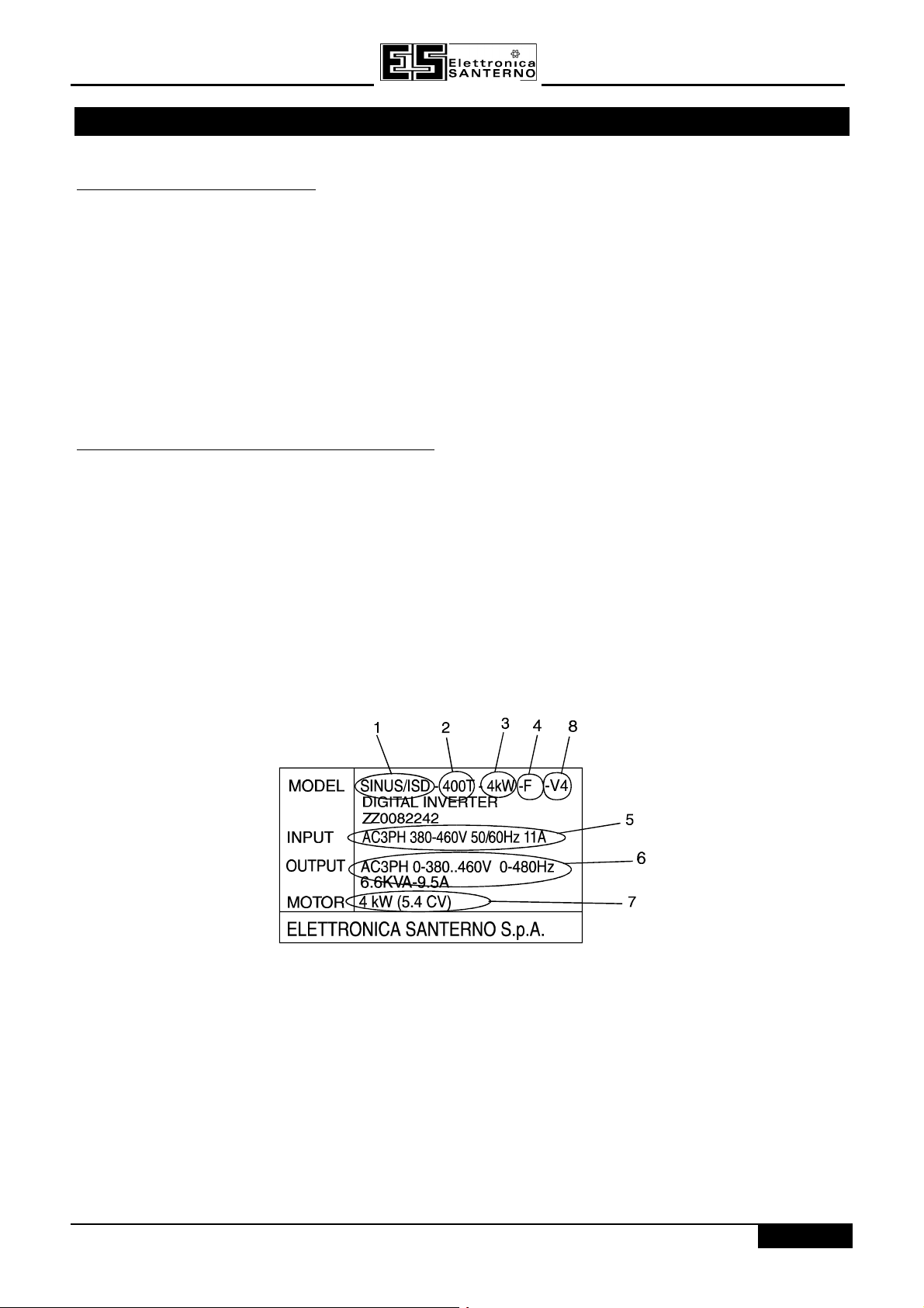
1 - 1 - model
2 - 2 - power class (200S: power supply 220 to 240 single-phase, 200T: power supply 220 to 240 three-phase,
400T power supply 380 to 460 three-phase)
3 - 3 - inverter size
4 - 4 - input filter (F means that there is internal RFI filter)
5 - 5 - input power mains features (AC3PH: three-phase alternating mains; 50/60 Hz; power supply
frequency; 11A: input current
6 - 6 - output features (AC 3PH: three-phase alternating, 0 * 380 to 460; output voltage (the maximum output
voltage depends on the power supply voltage); 0 to 480 Hz: output frequency
7 - 7 - motor (maximum power of the motor which can be connected)
8 - 8 - software version
1 - 1/2

15P0082B8
USER MANUAL
SINUS/ISD
1.31.3 ABOUT THIS MANUALABOUT THIS MANUAL
This manual is intended for use by the installer, user and programmer of the SINUS/ISD inverter. It assumes a
reasonable level of understanding in these three disciplines.
Note:
There is a column for you to record your application’s parameter settings in the table in Chapter 10. It is
important that you pass this manual on to any new user of this unit.
Please read all Safety Information before proceeding with the installation and operation of this unit.
1.3.1 INITIAL STEPS
Use the manual to help you plan the following:
InstallationInstallation
Know your requirements:
• certification requirements, CE conformance
• conformance with local installation requirements
• supply and cabling requirements
OperationOperation
Know your operator:
• how is it to be operated, local and/or remote?
• what level of user is going to operate the unit?
• decide on the best menu level for the Operator Station (where supplied)
Programming (Operator Station or suitable PC programming tool only)Programming (Operator Station or suitable PC programming tool only)
Know your application:
• install the most appropriate macro
• plan your “block diagram programming”
• enter a password to guard against illicit or accidental changes
• learn how to back-up your application data
• customise the Operator Station to the application
1.3.2 HOW THE MANUAL IS ORGANISED
The manual is divided into chapters and paragraphs. Page numbering restarts with every chapter, i.e. 1 - 2/2 is
Chapter 1, page 2 of 2 pages.
1.3.2.1 Application Block Diagrams
You will find these at the rear of the manual. The pages unfold to show a complete block diagram, these will
become your programming tool as you become more familiar with the SINUS/ISD ’s software.
1.3.2.2 Information for Users without an Operator Station
This symbol identifies important text for users operating the Inverter using the default (factory) set-
DEFAULT
up.
If the text is italic,
Station or suitable PC programming tool.
such as this
, then the information is especially for users without the Operator
1 - 2/2
SINUS/ISD
1
1
ACMOORTDIVRE21500VkW
2
2.02.0 AAN N OOVERVIEW OF THE VERVIEW OF THE IINVERTERNVERTER
2.12.1 COMPONENT IDENTICOMPONENT IDENTIFICATIONFICATION
7
12
HEALTH
RUN
15
15P0082B8
USER MANUAL
1
HEALTH LOCAL
SEQ
E
M
FWD
JOG
REV
STOPRUN
REF
PROG
L
R
RESET
11
1 2 3 4 5 6 7 8 9 10 11 12 13 14 15 16 17 18
10
3
14
CHARGE
L1 L2/NL3DC+DBRDC-
M1/UM2/V M3/W
8
9
4
9
13
6
5
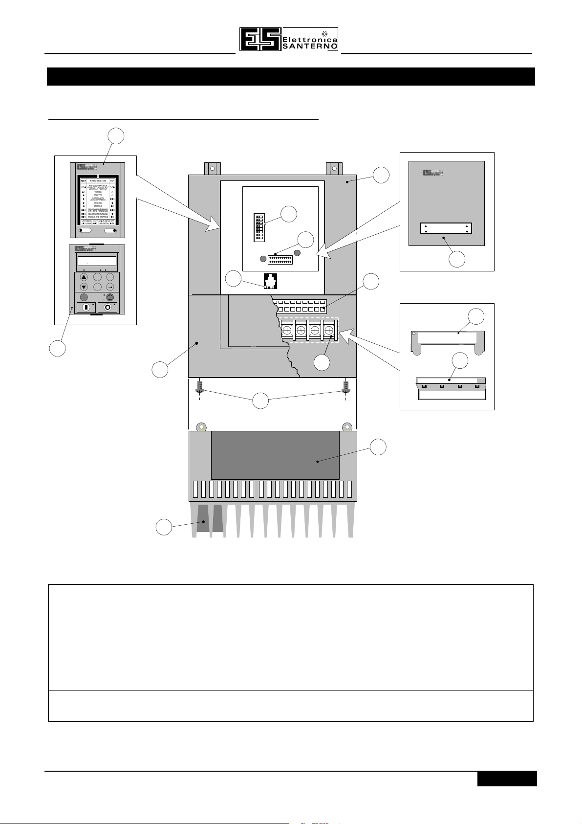
Figure 2-1 View of Component PartsFigure 2-1 View of Component Parts
11 Main Inverter assembly 99 Power terminals
22 Terminal cover retaining screw 1010 Control terminals
33 Optional technology box 1111 RS232 programming port
44 Terminal cover 1212 I/O configuration switches
55 Cooling fan (Type B only) 1313 Power terminal shield (Type A only)
66 Gland plate 1414 Power terminal shield (Type B only)
77 Standard front panel 1515 Technology box interface connected
88 Operator Station (optional)
Charge LED This can be seen through a viewing hole in the power terminal shield (item 14)
when the terminal cover (item 4) is removed on the SINUS/ISD Type A Inverter
2 - 1/4

15P0082B8
USER MANUAL
SINUS/ISD
2.22.2 CONTROL FEATURESCONTROL FEATURES
The Inverter is fully-featured when controlled using the optional Operator Station (or a suitable PC programming
tool).
DEFAULT
The `General’ control features below are not user-selectable when the unit is controlled using the
analog and digital inputs and outputs.
GeneralGeneral Output
Frequency
Switching
Frequency
Flux Control
Skip
Frequencies
Preset
Speeds
Stopping
Modes
Ramps
Raise/Lower
Jog
Logic
Functions
Value
Functions
Diagnostics
ProtectionProtection Trip
Conditions
Current Limit
Inputs/Inputs/
Analog Inputs
OutputsOutputs
Analog
Outputs
Digital Inputs
Digital
Outputs
Selectable 0-120Hz, 240Hz or 480Hz
Selectable 3kHz, 6kHz or 9kHz
(select 3kHz for all SINUS/ISD type B units if using
screened motor cable - maximum permitted length is 50
metres)
1. V/F control with linear or fan law profile
2. Sensorless vector with automatic flux control and
slip compensation
4 skip frequencies with adjustable skip band width
8 presets with programmable ramp rates
Ramp, ramp with hold, coast, dc injection, fast stop
Symmetric or asymmetric ramp up and down rates
Programmable MOP function
Programmable jog speed
10 programmable 3 input logic function blocks
performing NOT, AND, NAND, OR, NOR and XOR
functions
10 programmable 3 input value function blocks
performing IF, ABS, SWITCH, RATIO, ADD, SUB,
RATIO, TRACK/HOLD, and BINARY DECODE functions
Full diagnostic and monitoring facilities
Output short line to line, and line to earth
Overcurrent > 250%
Overvoltage and undervoltage
Heatsink overtemperature
Adjustable 50%-150%
2 configurable inputs - voltage or current
1 configurable output - voltage or current
7 configurable 24V dc inputs
2 configurable 24V dc open collector outputs
2 - 2/4
Table 2-Table 2-11 Control Features Control Features
SINUS/ISD
15P0082B8
USER MANUAL
2.32.3 PRODUCT-RELATED DEFAULT VALUESPRODUCT-RELATED DEFAULT VALUES
All examples given in this book are based on a UK, 230V, 50Hz, 0.75kW inverter. The parameters shown below
have values that can vary with build/configuration.
2.3.1 Language Dependant Defaults
These parameters (marked with “*” in function block descriptions and macro diagrams) are set to a value
depending on the
Note:
A “tag” is the unique number that identifes a parameter where information is stored.The concept of tags
and parameters is explained in Chapter 5: “The Operator Station”.
LANGUAGE 1 ENGLISH DEUTSCH FRANCAIS ESPANOL
MAX SPEED 57 50.0Hz 50.0Hz 50.0Hz 50.0Hz
BASE FREQUENCY 106 50.0Hz 50.0Hz 50.0Hz 50.0Hz
CONFIGURATION ID 339 AC MOTOR
LANGUAGE 1 ENGLISH { 0} { 0}
MAX SPEED 57 60.0Hz 50.0Hz 60.0Hz
BASE FREQUENCY 106 60.0Hz 50.0Hz 60.0Hz
CONFIGURATION ID 339 AC MOTOR
Language
portion of the Product Code.
TagTag English (UK)English (UK) German (GR)German (GR) French (FR)French (FR) Spanish (SP)Spanish (SP)
AC MOTOR
DRIVE
TagTag American (US)American (US) P 50Hz (P5)P 50Hz (P5) P 60Hz (P6)P 60Hz (P6)
DRIVE
DRIVE
AC MOTOR
DRIVE
CONV
FREQUENCE
AC MOTOR DRIVE
VARIADOR
ALTERNA
2.3.2 AC Supply Voltage and Power Rating Dependant Defaults
These parameters (marked with “**” in function block descriptions and macro diagrams) are set to a value
depending on the overall “power-build” of the Inverter indicated by the Product Code.
TagTag 0.75k0.75k
WW
230V230V
FULL LOAD CALIB 64 3.4A 6.2A 8.3A 2.0A 3.6A 4.8A 8.4A
NO LOAD CALIB 65 1.9A 3.6A 4.5A 1.1A 2.1A 2.7A 4.7A
STATOR RES 119 12.60 5.51 4.12 12.60 5.51 12.40 5.47
LEAKAGE INDUC 120 56.9 30.4 14.9 56.9 30.4 69.1 42.4
MUTUAL INDUC 121 626.0 333.7 257.2 626.0 333.7 783.9 446.2
MOTOR VOLTS 122 230.0V 230.0V 230.0V 400.0V 400.0V 400.0V 400.0V
MOTOR CONNECTION 124 DELTA DELTA DELTA STAR STAR DELTA DELTA
1.5kW1.5kW
230V230V
2.2kW2.2kW
230V230V
0.75k0.75k
WW
400V400V
1.5kW1.5kW
400V400V
2.2kW2.2kW
400V400V
4.0kW4.0kW
400V400V
2 - 3/4
15P0082B8
PROCESSOR
POWER
CONTROL
M1M2M3
PE
TERMINALS
CONTROL
RS232
PROGRAMMING
TECHNOLOGY BOX
INTERFACE
TECHNOLOGY BOX
CONNECTOR
USER MANUAL
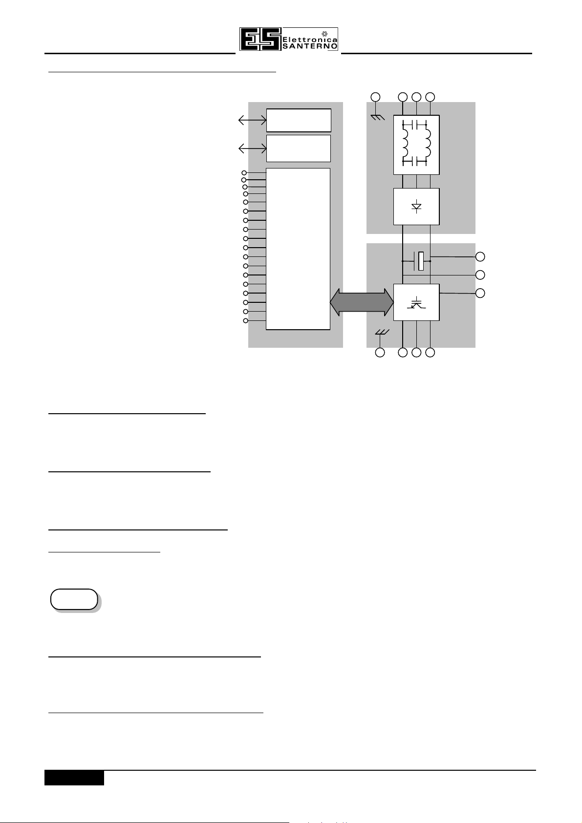
2.42.4 FUNCFUNCTIONAL OVERVIEWTIONAL OVERVIEW
PORT
18
17
16
15
14
13
12
11
10
9
8
7
6
5
4
3
2
1
SINUS/ISD
PE L1 L2 L3
INTERFACE
FILTER
DC+
DC-
DBR
Figure 2-2 Functional Block DiagramFigure 2-2 Functional Block Diagram
2.4.1 FILTER BOARD
This two-stage filter consists of common and differential mode elements. It attenuates the Inverter noise
produced on to the mains supply. Mains supply is applied to terminals L1, L2 (N) and L3.
2.4.2 POWER BOARD
DC link capacitors smooth the dc voltage output prior to the Inverter power stage. The IGBT (Insulated Gate Bipolar Transistor) output stage converts the dc input to a three phase output used to drive the motor.
2.4.3 CONTROL BOARD
2.4.3.1 Processor
The processor provides for a range of analog and digital inputs and outputs, together with their reference
supplies. For further details refer to Chapter 11: “Technical Specifications” - Control Terminals.
The I/O configuration switches (SW1 & SW2) on the control board can be seen through the outer
DEFAULT
2.4.3.2 Technology Box Interface
casing of the Inverter when the blank cover, the Operator Station, or the Technology Box option is
removed. These switches configure the analog i/o terminals. Refer to Chapter 6: “Programming
Your Application” - ANALOG INPUT and ANALOG OUTPUT.
This is a multi-way connector and processor bus interface with control signals allowing various technology box
options to be fitted to the Inverter.
2.4.3.3 Operator Station Interface
This is a non-isolated RS232 serial link for communication with the Operator Station. Alternatively, a PC running
Elettronica Santerno “SINUS/ISD Configuration Program” Windows-based configuration software (or some other
suitable PC programming tool) can be used to graphically program and configure the Inverter.
2 - 4/4

SINUS/ISD
15P0082B8
USER MANUAL
3.0 INSTALLING THE INVERTER
IMPORTANT: Read Chapter 12: “Certification for the Inverter” before installing this unit.
3.13.1 REQUIREMENTS FOR EMC COMPLIANCEREQUIREMENTS FOR EMC COMPLIANCE
All Variable Speed Drives (VSDs) potentially produce electrical emissions which are radiated into the
environment and conducted back into the ac supply. VSDs are inherently immune to any additional external
electrical noise. The following information is provided to maximise the Electro Magnetic Compatibility (EMC) of
VSDs and systems in their intended operating environment, by minimising their emissions and maximising their
immunity.
3.1.1 MINIMISING RADIATED EMISSIONS
EN55011 radiated emission measurements are made between 30MHz and 1GHz in the far field at a distance of
10 to 30 metres. Limits lower than 30MHz or in close proximity are not specified. Emissions from individual
components tend to be additive.
• Use a screened/armoured cable between VSD/cubicle and motor containing the motor protective earth (PE)
connection. It should have a 360°° screen termination. Earth screen at both ends connecting to the motor
frame and cubicle. Maintain the screen integrity using 360° terminations.
Note:
• Keep unshielded cable as short as possible inside the cubicle.
• Always maintain the integrity of the shield.
• If the cable is interrupted to insert contactors etc., re-connect the screen using the shortest possible route.
• Keep the length of screen stripped-back as short as possible when making screen connections.
• Ideally use 360° screen terminations using cable glands or `U’ clips on power screen rails.
If a shielded cable is not available, lay unshielded motor cables in a metal conduit which will act as a shield. The
conduit must be continuous with a direct electrical contact to the VSD and motor housing. If links are necessary,
use braid with a minimum cross sectional area of 10mm2.
Note:
Some hazardous area installations may preclude direct earthing at both ends of the screen, in this case
earth one end via a 1µF 50Vac capacitor, and the other as normal.
Some motor gland boxes and conduit glands are made of plastic, if this is the case, then braid must be
connected between the screen and the chassis. In addition at the motor end, ensure that the screen is
electrically connected to the motor frame since some terminal boxes are insulated from the frame by
gasket/paint.
3.1.2 EARTHING REQUIREMENTS
IMPORTANT: Protective earthing always takes precedence over EMC earthing.
3.1.2.1 Protective Earth (PE) Connections
Note:
In accordance with the installation requirements of EN60204, only one protective earth conductor is
permitted at each protective earth terminal contacting point.
Local wiring regulations may require the protective earth connection of the motor to be connected locally, i.e. not
as specified in these instructions. This will not cause shielding problems because of the relatively high RF
impedance of the local earth connection.
3.1.2.2 EMC Earth Connections
For compliance with EMC requirements, we recommend that the “0V/signal ground” is separately earthed. When
a number of units are used in a system, these terminals should be connected together at a single, local earthing
point.
3 - 1/14

15P0082B8
USER MANUAL
Control and signal cables for the encoder, all analog inputs, and communications require screening with the
screen connected only at the VSD end. However, if high frequency noise is still a problem, earth screen at the
non VSD end via a 0.1µF capacitor.
SINUS/ISD
Note:
Connect the screen (at the VSD end) to the VSD protective point, and not to the control board terminals.
3.1.3 CABLING REQUIREMENTS
Note:
3.1.3.1 Planning Cable Runs
• Use the shortest possible motor cable lengths.
• Use a single length of cable to a star junction point to feed multiple motors, refer to “Star Point Earthing”
• Keep electrically noisy and sensitive cables apart.
• Keep electrically noisy and sensitive parallel cable runs to a minimum. Separate parallel cable runs by at
• Sensitive cables should cross noisy cables at 90°.
• Never run sensitive cables close or parallel to the motor, dc link and braking chopper circuit for any
• Never run supply, dc link or motor cables in the same bundle as the signal/control and feedback cables,
3.1.3.2 Increasing Motor Cable Length
Because cable capacitance and hence conducted emissions increase with motor cable length, conformance to
EMC limits is only guaranteed with the specified internal ac supply EMC filter option using a maximum cable
length as specified in Chapter 11: “Technical Specifications”.
Screened/armoured cable has significant capacitance between the conductors and screen which increases
linearly with cable length (typically 200pF/m but varies with cable type and current rating).
Refer to Chapter 11: “Technical Specifications” for additional Cabling Requirements.
page 3-4/14.
least 0.25 metres. For runs longer than 10 metres, separation should be increased proportionally. For
example if the parallel runs were 50m, then the separation would be (50/10) x 0.25m = 1.25m.
distance.
even if they are screened.
Long cable lengths may have the following undesirable effects:
• Tripping on `overcurrent’ as the cable capacitance is charged and discharged at the switching frequency.
• Producing increased conducted emissions which degrade the performance of the internal ac supply EMC
filter due to saturation.
• Causing RCDs (Residual Current Devices) to trip due to increased high frequency earth current.
• Producing increased heating inside the internal ac supply EMC filter from the increased conducted emissions.
These effects can be overcome by adding motor chokes or an EMC motor output filter at the output of the VSD.
3 - 2/14
SINUS/ISD
AC Supply
Motor
motor cable screen
PE
PE
SINUS/
PE
15P0082B8
USER MANUAL
3.1.4 EMC INSTALLATION OPTIONS
The unit, when installed for Class B operation, will be compliant with EN55011 (1991) / EN55022 91994) for
radiated emissions, as described below.
Note:
Refer to Chapter 11: “Technical Specifications” for details on Cabling Requirements.
3.1.4.1 Screening & Earthing (cubicle mounted, Class B)
Note:
The unit is installed for Class B operation when mounted inside a cubicle having 10dB attenuation between 30
and 100MHz (typically the attenuation provided by a metal cabinet with no aperture of dimension greater than
0.15m), using the internal ac supply EMC filter and having metal cabling requirements.
Note:
The VSD and associated equipment are mounted onto a conducting, metal mounting panel. Do not use cubicle
constructions that use insulating mounting panels or undefined mounting structures. Cables between the VSD
and motor must be screened or armoured and terminated at the entrance to the cubicle.
Single VSD - Single Motor
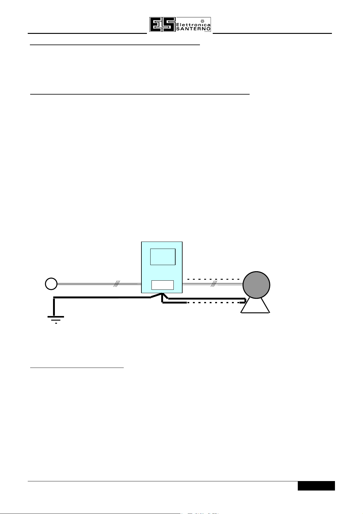
Apply a single point earthing strategy for a single VSD mounted in a cubicle as shown below.
The protective earth connection (PE) to the motor must be run inside the screened cable between the motor and
VSD and be connected to the motor protective earth terminal on the VSD.
The installation requirements of local safety standards must be achieved regarding the safety of
electrical equipment for machines.
Radiated magnetic and electric fields inside the cubicle may be high and any components fitted inside
must be sufficiently immune.
ISD
Figure 3-1 EMC and Safety Earthing CablingFigure 3-1 EMC and Safety Earthing Cabling
Single VSD - Multiple Motors
Note:
IMPORTANT: If connecting multiple motors to a single VSD, use a star junction point for motor cable
Refer to Chapter 13: “Application Notes” - Using Multiple Motors on a Single Inverter.
connections, refer to Star Point Earthing below. Use a metal box with entry and exit cable glands
to maintain shield integrity.
3 - 3/14
15P0082B8
Incoming Safety Earth (PE)
USER MANUAL
SINUS/ISD
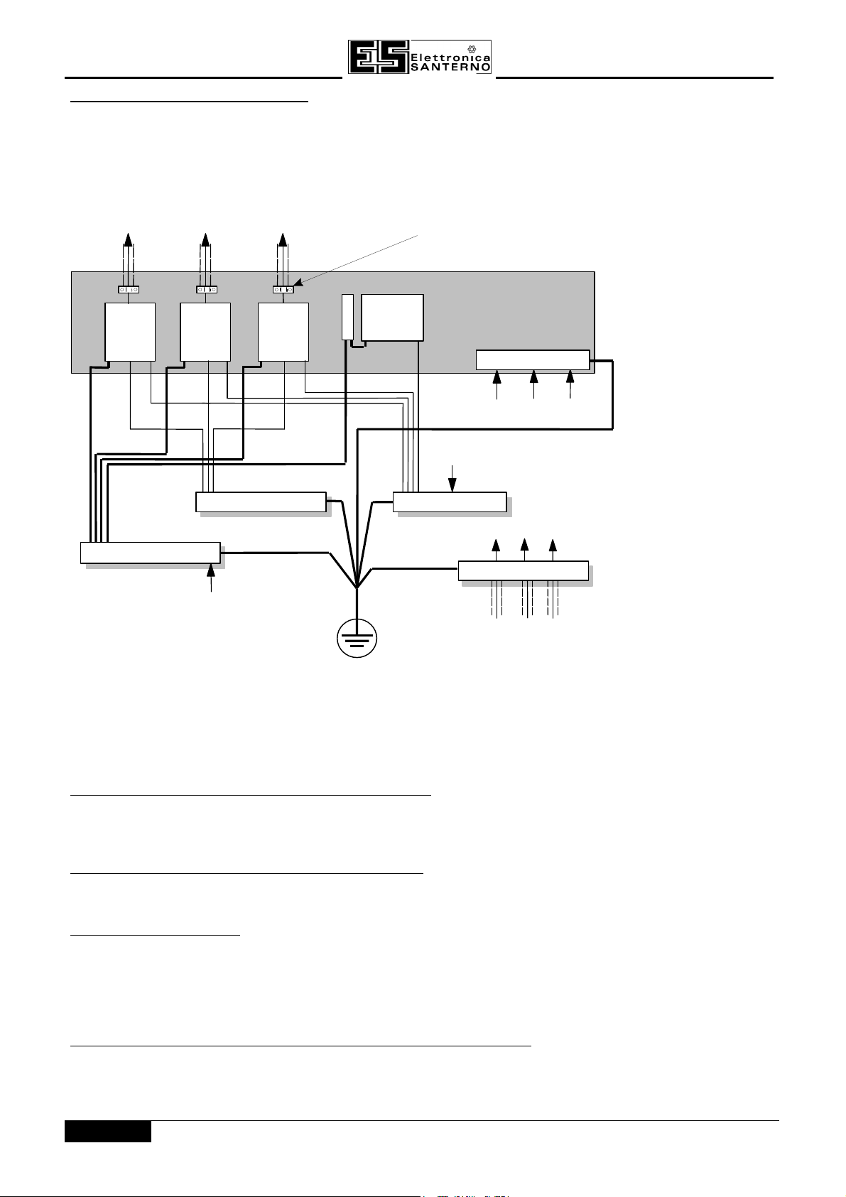
3.1.4.2 Star Point Earthing
A star-point earthing policy separates `noisy’ and `clean’ earths. Four separate earth busbars (three are
insulated from the mounting panel) connect to a single earth point (star point) near the incoming safety earth
from the main supply. Flexible, large cross-section cable is used to ensure a low HF impedance. Busbars are
arranged so that connection to the single earth point is as short as possible.
to motor to motor to motor
screened screened
VSD
PE
PE
0A = 0 Volts Analogue
0D = 0 Volts Digital
PE = Protective Earth
f = External Filter
VSD = Variable Speed Drive
PLC = Programmable Logic Controller
0D 0D
0A 0A
Dirty Earth
VSD VSD
PE
PE
Analogue Clean Earth
110V
Control
PE
0A
PE
STAR POINT
U-clip used to terminate screen
connection to the back panel
Back Panel
PLC
f
Metal Work Earth
PE
0D
0D
24V Control
Digital Clean Earth
Signal/Control Screen
all screened signals not
going directly to a VSD
Doors
Back
Panel
unscreened signals
Metal
Work
Figure 3-2 Star Point EarthingFigure 3-2 Star Point Earthing
1 Clean Earth Busbar (insulated from the mounting panel)
Used as a reference point for all signal and control cabling. This may be further subdivided into an analogue and
a digital reference busbar, each separately connected to the star earthing point. The digital reference is also
used for any 24V control.
2 Dirty Earth Busbar (insulated from the mounting panel)
Used for all power earths, i.e. protective earth connection. It is also used as a reference for any 110 or 220V
control used, and for the control transformer screen.
3 Metal Work Earth Busbar
The back panel is used as this earth busbar, and should provide earthing points for all parts of the cubicle
including panels and doors. This busbar is also used for power screened cables which terminate near to (10cm)
or directly into a VSD - such as motor cables, braking choppers and their resistors, or between VSDs - refer to
the appropriate product manual to identify these. Use U-clips to clamp the screened cables to the back panel to
ensure optimim HF connection.
4 Signal/Control Screen Earth Busbar (insulated from the mounting panel)
Used for signal/control screened cables which do notdo not go directly to the VSD. Place this busbar as close as
possible to the point of cable entry. `U’ clamp the screened cables to the busbars to ensure an optimum HF
connection.
3 - 4/14

SINUS/ISD
15P0082B8
USER MANUAL
3.1.4.3 Sensitive Equipment
The proximity of the source and victim circuit has a large effect on radiated coupling. The electromagnetic fields
produced by VSDs falls off rapidly with distance from the cabling/cubicle. Remember that the radiated fields from
EMC compliant drive systems are measured at least 10m from the equipment, over the band 30-1000MHz. Any
equipment placed closer than this will see larger magnitude fields, especially when very close to the Inverter.
Do not place magnetic/electric field sensitive equipment within 0.25 metres of the following parts of the VSD
system:
• Variable Speed Drive (VSD)
• EMC motor output filters
• Input or output chokes/transformers
• The cable between VSD and motor (even when screened/armoured)
• Connections to external braking chopper and resistor (even when screened/armoured)
• AC/DC brushed motors (due to commutation)
• DC link connections (even when screened/armoured)
• Relays and contactors (even when suppressed)
From experience, the following equipment is particularly sensitive and requires careful installation.
• Any transducers which produce low level analog outputs (<1V) , e.g. load cells, strain gauges,
thermocouples, piezoelectric transducers, anemometers, LVDTs
• Wide band width control inputs (>100Hz)
• AM radios (long and medium wave only)
• Video cameras and closed circuit TV
• Office personal computers
• Capacitive devices such as proximity sensors and level transducers
• Mains borne communication systems
• Equipment not suitable for operation in the intended EMC environment, i.e. with insufficient immunity to new
EMC standards
3 - 5/14
15P0082B8
All Dimensions are in millimetres ( inches )
Model
HH1WW1W2
D
Fixings
Maintain a minimum clearance for ventilation of 100 mm above and below.
All Dimensions are in millimetres ( inches )
Model
HH1WW1W2
D
Fixings
USER MANUAL
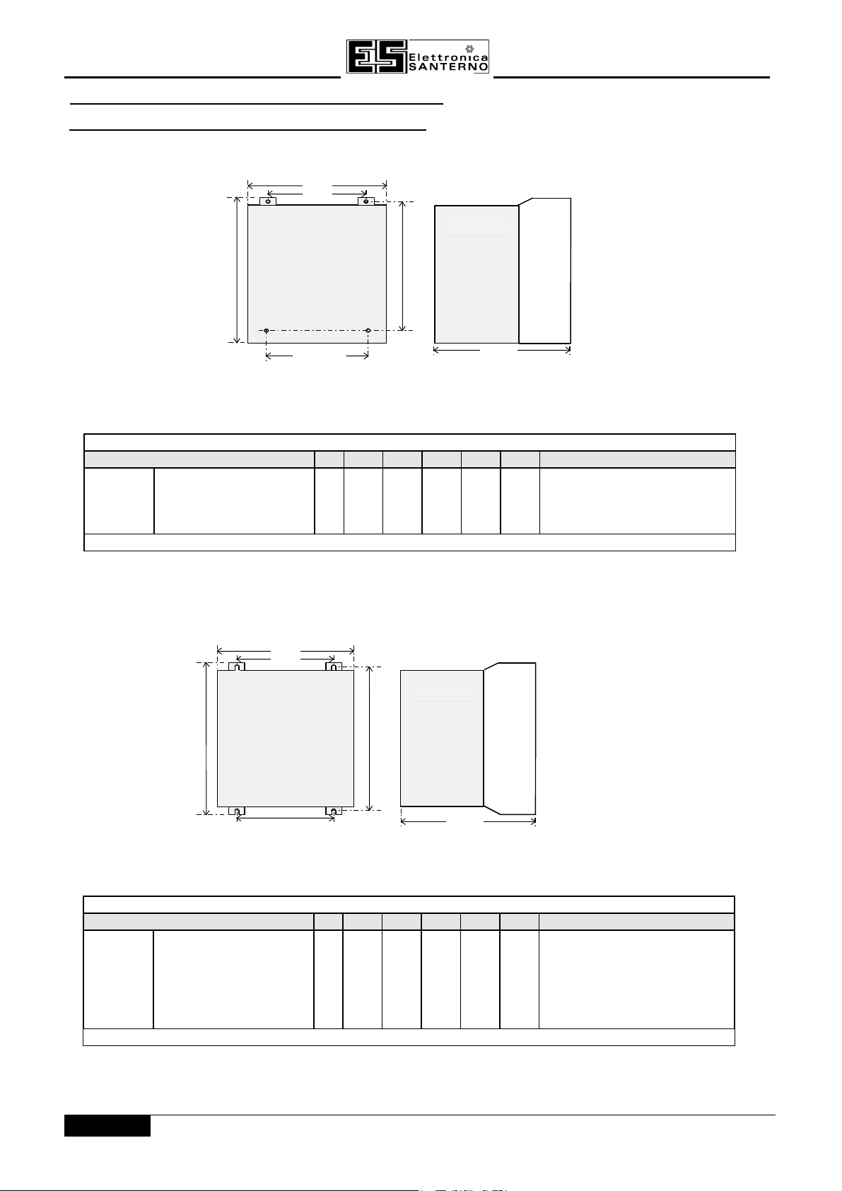
3.23.2 MECHANICAL INSTALLATIONMECHANICAL INSTALLATION
3.2.1 MOUNTING THE INVERTER
The unit must be mounted vertically on a solid, flat, vertical surface.
W
W 1
SINUS/ISD
Control
H
W 2
H 1
Heat
Sink
D
Figure 3-3 Mechanical Dimensions for SINUS/ISD Type AFigure 3-3 Mechanical Dimensions for SINUS/ISD Type A
A SINUS/ISD 200 S - 0.75 Mounting Holes 5.5 mm.
SINUS/ISD 200 S - 1.5 198 173.5 155 109 114 154.5 Use M5 Fixings.
SINUS/ISD 200 T - 0.75 Weight 3 kg
SINUS/ISD 200 T - 1.5
Table 3-1 Mechanical Dimensions for SINUS/ISD Type ATable 3-1 Mechanical Dimensions for SINUS/ISD Type A
W
W 1
Control
H
W 2
H 1
Heat
Sink
D
Figure 3-4 Mechanical Dimensions for SINUS/ISD Type BFigure 3-4 Mechanical Dimensions for SINUS/ISD Type B
B SINUS/ISD 200 S - 2.2
SINUS/ISD 200 T - 2.2
SINUS/ISD 400 T - 0.75 Mounting Holes 4.8 mm.
SINUS/ISD 400 T - 1.5
SINUS/ISD 400 T - 2.2
233 223 171 129.5 129.5 181 Use M4 Fixings.
Weight 4.3 kg
SINUS/ISD 400 T - 4
Maintain a minimum clearance for ventilation of 100 mm above and below.
Table 3-2 Mechanical Dimensions for SINUS/ISD Type BTable 3-2 Mechanical Dimensions for SINUS/ISD Type B
3 - 6/14
SINUS/ISD
15P0082B8
USER MANUAL
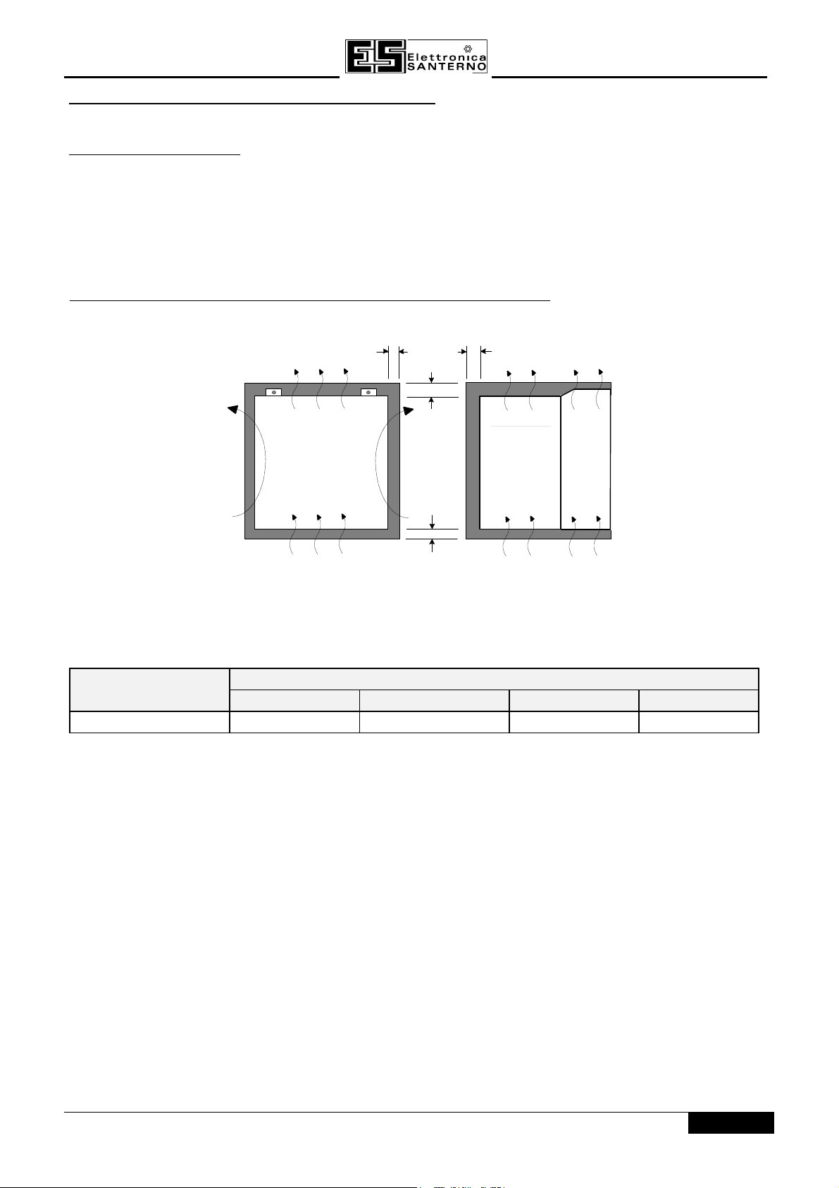
3.2.2 MINIMUM AIR CLEARANCES
3.2.2 .1 Ventilation
The inverter gives off heat in normal operation and must therefore be mounted to allow the free flow of air
through the ventilation slots and heatsink. Maintain minimum clearances for ventilation as given in the tables
below to ensure heat generated by other adjacent equipment is not transmitted to the Inverter. Be aware that
other equipment may have its own clearance requirements. When mounting two or more SINUS/ISDs together,
these clearances are additive.
Ensure that the mounting surface is normally cool.
3.2.2.2 Air Clearance for an IP20 Product/Application
The Inverter must be mounted in a suitable cubicle.
J
L
AIR FLOW
Figure 3-5 Air Clearance for an IP20 Product/ApplicationFigure 3-5 Air Clearance for an IP20 Product/Application
SINUS/ISD TypeSINUS/ISD Type Clearances for Standard ProductClearances for Standard Product
JJ KK LL MM
A & B 15 0 (zero) 70 80
M
K
Control
Heat
Sink
3 - 7/14
15P0082B8
t
b
P
c
USER MANUAL
SINUS/ISD
3.3 DYNAMIC BRAKING3.3 DYNAMIC BRAKING
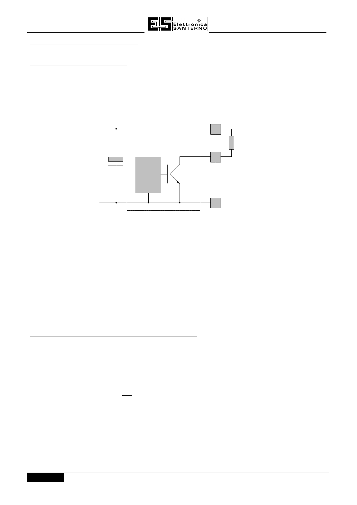
3.3.1 INTRODUCTION
During deceleration, or with an overhauling load, the motor acts as a generator. Energy flows back from the
motor into the DC link capacitors within the Frequency Inverter. This causes the DC link voltage to rise. If the
DC link voltage exceeds 810V for the 400V build (or 420V for the 230V build) then the Frequency Inverter will trip
to protect the capacitors and the inverter power devices. The amount of energy that can be absorbed in the
capacitors is relatively small; typically more than 20% braking torque will cause the Frequency Inverter to trip on
overvoltage. Dynamic braking increases the braking capability of the Frequency Inverter by dissipating the
excess energy in a high power resistor connected across the DC link (refer to Figure 3.6).
EXTERNAL
RESISTOR
NETWORK
+
GATE
DRIVE
CIRCUIT
Figure 3-6 - Dynamic Braking CircuitFigure 3-6 - Dynamic Braking Circuit
When the DC link voltage rises above 750V for the 400V build (385V for the 230V build), the brake unit switches
the external resistor network across the DC link. The brake unit switches off again when the DC link voltage falls
below the threshold level. The amount of energy produced by the motor during regeneration depends upon the
RAMP DOWN TIME parameter and the inertia of the load.
Note: The dynamic braking circuit is designed to cope with short term stopping or braking only. It is not rated
for a continuously overhauling load.
All SINUS/ISD units are supplied without braking resistors. The following paragraphs should be used as a guide
to calculate the braking requirements of the system.
3.3.2 BRAKE RESISTOR SELECTION
Brake resistor assemblies must be rated to absorb both peak braking power during deceleration and the average
power over the complete cycle.
2
Peak braking power
0 0055J n n
=
Average braking power P
= x t
av
× −. ( )
pk
t
2
1
2
b
W
( )
J ð total inertia (kgm2)
n1ð initial speed (rpm)
n2ð final speed (rpm)
tbð braking time (s)
tcð cycle time (s)
3 - 8/14
SINUS/ISD
Information on the peak power rating and the average power rating of the resistors must be obtained from the
resistor manufacturer. Alternatively if this information is not available then a large safety margin must be
incorporated to ensure that the resistors are not overloaded. Elettronica Santerno can supply suitable brake
resistor assemblies as detailed over.
By connecting these resistors in series and in parallel the braking capacity can be selected for the application.
The minimum resistance of the combination shouldn't be less than that specified in subchapter 3.3.3.
The resistor(s) must be specified to the maximum DC link voltage (810V for the 400V models, 420V for the 230V
models).
15P0082B8
USER MANUAL
3.3.3 SPECIFICATION OF THE DYNAMIC BRAKING SWITCH
SINUS/ISD
CURRENT RATING (max. 20s) 4 A 8 A 4 A 8 A 12 A
MAX. DUTY CYCLE 30 %
MIN. RESISTOR VALUE
200S -T - 0.75÷1.5
100 Ω 56 Ω 100 Ω 75 Ω
200S - T - 2.2
400T - 0.75÷1.5
400T - 2.2 400T -4
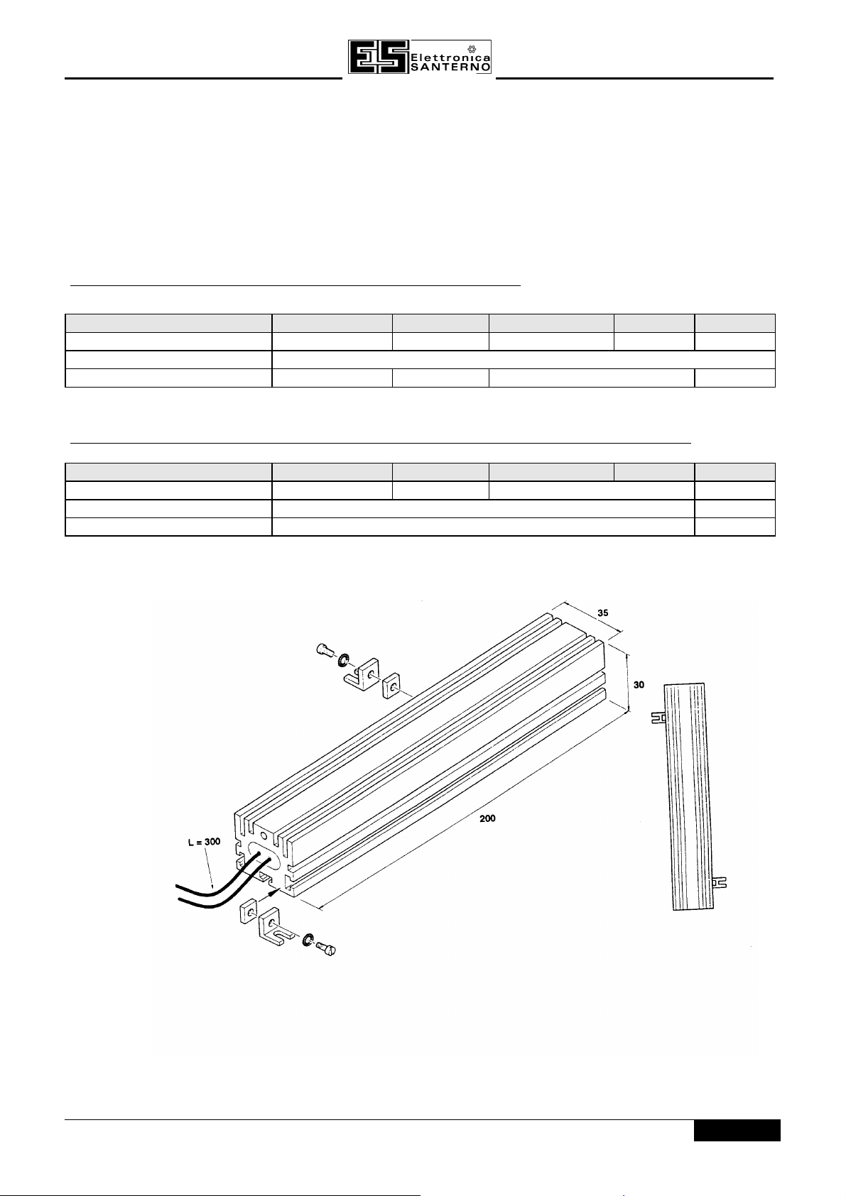
3.3.4 SPECIFICATION AND OVERALL DIMENSIONS OF THE BRAKING RESISTORS
SINUS/ISD
VALUE
POWER 350 W 550 W
DIMENSIONS Figure 3-7 Fig. 3-8
200S -T- 0.75÷1.5
100 Ω 56 Ω 100 Ω 75 Ω
200S - T - 2.2
400T - 0.75÷1.5
400T - 2.2 400T -4
Figure 3-7 – Braking resistor (350 W)Figure 3-7 – Braking resistor (350 W)
3 - 9/14
15P0082B8
inverter
motor
brake resistor
(noisy)
(noisy)
signal/control cable
(sensitive)
power
supply
(clean)
cable
fuse or suitable
circuit breaker
(RCD not
line
choke
(noisy)
motor
motor
internal ac supply EMC filter
(noisy)
filter
motor
output
EMC
USER MANUAL
SINUS/ISD
POWER W L P
550 195 174
Figure 3-8 – Braking resistor (550 W)Figure 3-8 – Braking resistor (550 W)
3.4 3.4 ELECTRICAL INSTELECTRICAL INSTALLATIONALLATION
IMPORTANT: Please read the Safety Information on PAGE 2 before proceeding.
3.4.1 WIRING THE INVERTER
WARNING!
Ensure that all wiring is electrically isolated and cannot be made “live”
unintentionally by other personnel.
Note:
Refer to Chapter 11: “Technical Specifications” for additional Cabling Requirements and Terminal Block
Wire Sizes.
choke
cable
3 - 10/14
recommended)
Figure 3-9 Cabling RequirementsFigure 3-9 Cabling Requirements
SINUS/ISD
clamp connection)
Cables are considered to be electrically
sensitive, clean
or
noisy
. You should already have planned your cable
15P0082B8
USER MANUAL
routes with respect to segregating these cables for EMC compliance.
If not, refer to the beginning of this chapter.
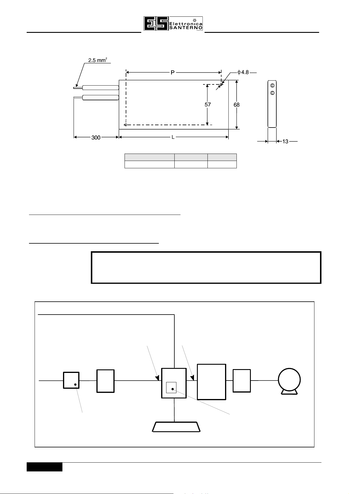
3.4.1.1 Cable Gland Requirements
Use a metal gland to connect to the internally earthed gland plate. It must be capable of securing a 360 degree
screened connection to give EMC compliance. A 360 degree screened connection can be achieved as shown.
The receiving hole in the gland plate has a compromised diameter of 22.8mm to accept metric M20, PG16 and
American ½” NPT cable gland sizes.
Figure 3-10 360 Degree Screened ConnectionFigure 3-10 360 Degree Screened Connection
3.4.1.2 Earth Connections
The unit must be permanently earthedpermanently earthed using two independent earth conductors. Protect the incoming mains
supply using a suitable fuse or circuit breaker as shown in Chapter 11: “Technical Specifications” - Power
Details.
IMPORTANT: The Inverter fitted with an internal ac supply EMC filter is only suitable for earth referenced
supplies (TN). Refer to “Earth Fault Monitoring Systems”, page 3-14/14.
3.4.1.3 Power Wiring Connections
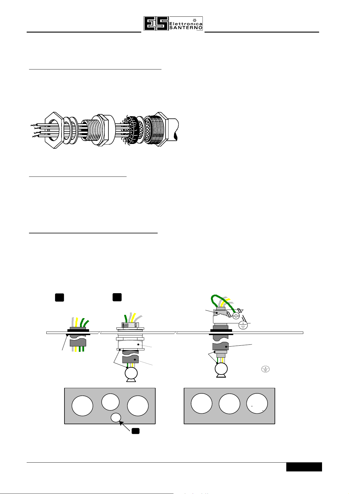
1. Remove the terminal cover retaining screws and lift off the terminal cover.
2. Remove the internal power terminal shield.
3. Feed the power supply and motor cables into the inverter through the metal gland plate using the correct
cable entries, and connect to the power terminals. Tighten the terminals to a torque of 1.0Nm (9 in.lb). Refer
to Figure 3-12 Power Wiring and Earth Connections.
4. Re-fit the internal power terminal shield.
standard fitment
1
rubber grommet
rubber
grommet
power
supply
PE
control
metal cable gland
2
M
motor
(metal
gland)
metal gland must
have 360 degree
screened connection
for EMC compliance
power wiring
to motor
screen
power
supply
PE
M
control
earth clamp connection
3
(Type A only)
fit earth clamp
over cable screen
power wiring
to motor
International
grounding symbol
Protective Earth
PE
motor
(metal
gland)
gland plate
motor
Type A Gland Plate
3
(if using earth
Type B Gland Plate
Figure 3-11 Cable and Screen Fixings showing recommended usage of Gland PlateFigure 3-11 Cable and Screen Fixings showing recommended usage of Gland Plate
3 - 11/14
15P0082B8
123456789
101112131415161718
Ω
USER MANUAL
brake resistor
L1 L2/N DC+ DBR DC- M1/U M2/V M3/W
Brakeresistorand cablemust bescreened
if notfittedinside acontrolcubicle
L1
SINUS/ISD
brake resistor
L2
DC+ DBR DC- M1/U M2/V M3/W
L3
powersupply motor
1 2
Single Phase Input
PE1 PE2
2 3
1
Type A
only
Three Phase Input
powersupply
1 2
PE1 PE2
motor
1
3
2
Type A
only
Figure 3-12 Power Wiring and Earth ConnectionsFigure 3-12 Power Wiring and Earth Connections
3.4.1.4 Control Wiring Connections
Note:
1. Feed the control cables into the inverter through the metal gland plate and connect to the control terminals.
2. Refit and secure the terminal cover using the retaining screws.
Note:
Use screened control cables to comply with EMC requirements.
The diagram below shows the typical control connections required for operation as a simple speed
controller.
Refer to Chapter 11: “Technical Specifications” for Control Terminal information
Refer to Chapter 6: “Programming Your Application” for ANALOG INPUT and ANALOG OUTPUT
configuration switch settings.
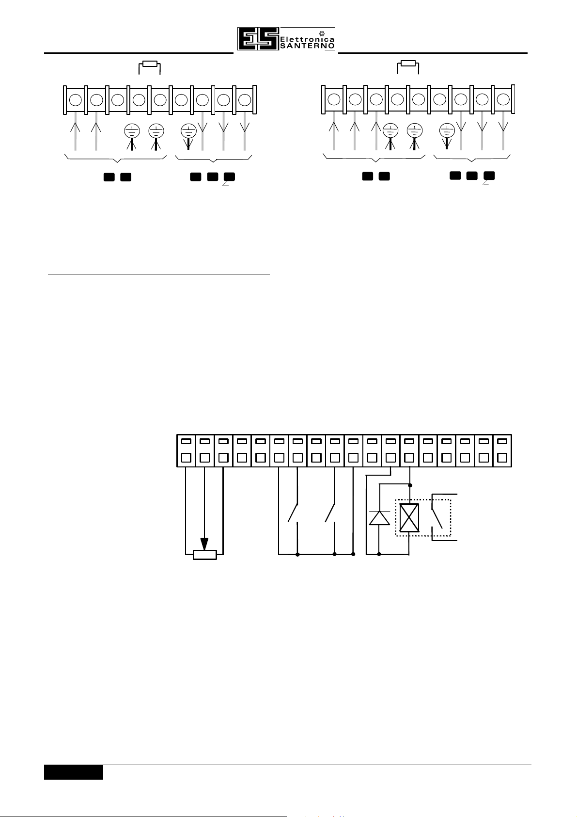
CONTROL TERMINALSCONTROL TERMINALS
1.1. 0 V REF0 V REF
2.2. Analog input 1 (speed)Analog input 1 (speed)
3.3. +10 V REF+10 V REF
4.4. Analog input 2 (speed trim)Analog input 2 (speed trim)
5.5. Analog output 2 (ramp out)Analog output 2 (ramp out)
6.6. +24 V+24 V
7.7. Digital input 1 (Run)Digital input 1 (Run)
8.8. Digital input 2 (Reset)Digital input 2 (Reset)
9.9. Digital input 3 (Direction)Digital input 3 (Direction)
10.10. Digital input 4 (Ext Trip)Digital input 4 (Ext Trip)
11.11. Digital input 5 (Jog)Digital input 5 (Jog)
12.12. 0 V0 V
13.13. Digital output 1 (Health)Digital output 1 (Health)
14.14. Digital input 2 (Run)Digital input 2 (Run)
15.15. 0V0V
16.16. See Note ASee Note A
17.17. See Note BSee Note B
18.18. +24 V+24 V
10k
Speed
Setpoint
Run Direction
Figure 3-13 Typical Connection to the Control TerminalsFigure 3-13 Typical Connection to the Control Terminals
Note A: Note A: DIGITAL INPUT 6 or ENCODER SIGNAL CHANNEL A
Nota B:Nota B: DIGITAL INPUT 7 or ENCODER SIGNAL CHANNEL B
*
Health Relay
24V 50mA maximum
* Diode must be fitted across relay coil to prevent
damage to control circuit
3 - 12/14
SINUS/ISD
15P0082B8
USER MANUAL
3.4.2 OPTIONAL EQUIPMENT INSTALLATION DETAILS
3.4.2.1 EMC Filters
WARNING!
Do not use an internal or external ac supply EMC filter with supplies that are not
balanced with respect to earth (IT). They must only be used with earth referenced
supplies (TN).
Do not touch filter terminals or cabling for at least 3 minutes after removing the ac
supply.
Only use the ac supply filter with a permanent earth connection.
EMC Motor Output Filter
This can help the Inverter achieve EMC and filter thermal conformance with cable lengths greater than those
specified. It also ensure longer motor life by reducing the high voltage slew rate and overvoltage stresses. Mount
the filter as close to the VSD as possible. Please refer to Elettronica Santerno for the selection of a suitable filter.
3.4.2.2 Line Chokes (input)
Line chokes may be used to reduce the harmonic content of the supply current where this a particular
requirement of the application or where greater protection from mains borne transients is required.
Please refer to Elettronica Santerno for the selection of a suitable filter.
3.4.2.3 Motor Chokes (output)
Installations with longer than specified motor cable runs may suffer from nuisance overcurrent trips, refer to
Chapter 11: “Technical Specifications” - Cabling Requirements for maximum cable lengths. A choke may be
fitted in the inverter output to limit capacitive current. Screened cable has a higher capacitance and may cause
problems in shorter runs. The recommended choke values are shown in the table below.
Inverter kWInverter kW Choke InductanceChoke Inductance RMS Current RatingRMS Current Rating CodeCode
0.75
1.5
2.2 1.1mH 20A IM0114100
Table 3-3 Recommended Choke Values for 220-240V InvertersTable 3-3 Recommended Choke Values for 220-240V Inverters
Note:
Motor chokes must be fitted for 380-460V units with screened cable runs in excess of 50m; limit the
switching frequency to 3kHz in these applications. Refer to Chapter 6: “Programming Your Application” PATTERN GEN.
Inverter kWInverter kW Choke InductanceChoke Inductance RMS Current RatingRMS Current Rating CodeCode
0.75
1.5
2.2
3.7 1.1mH 20A IM0114100
2.2mH 10A IM0114000
2.2mH 10A IM0114000
Table 3-4 Recommended Choke Values for 380-460V InvertersTable 3-4 Recommended Choke Values for 380-460V Inverters
3.4.2.4 Output Contactors
Output contactors can be used, although we recommend that this type of operation is limited to emergency use
only, or in a system where the inverter can be inhibited before closing or opening this contactor.
3 - 13/14

15P0082B8
USER MANUAL
SINUS/ISD
3.4.2.5 Earth Fault Monitoring Systems
We do not recommend the use of circuit breakers (e.g. RCD, ELCB, GFCI), but where their use is mandatory,
they should:
• Operate correctly with dc and ac protective earth currents (i.e. type B RCDs as in Amendment 2 of IEC755).
• Have adjustable trip amplitude and time characteristics to prevent nuisance tripping on switch-on.
When the ac supply is switched on, a pulse of current flows to earth to charge the internal/external ac supply
EMC filter’s internal capacitors which are connected between phase and earth. This has been minimised in
Elettronica Santerno’s filters, but may still trip out any circuit breaker in the earth system. In addition, high
frequency and dc components of earth leakage currents will flow under normal operating conditions. Under
certain fault conditions larger dc protective earth currents may flow. The protective function of some circuit
breakers cannot be guaranteed under such operating conditions.
WARNING!
Circuit breakers used with VSDs and other similar equipment are not suitable for
personnel protection. Use another means to provide personal safety.Refer to
prEN50178 (1995) / VDE0160 (1994) / EN60204-1 (1994)
3 - 14/14

SINUS/ISD
4.0 OPERATING THE INVERTER
15P0082B8
USER MANUAL
DEFAULT
By default, the Inverter will operate in Remote Start/Stop and Remote Speed Control. Analog
and digital inputs and outputs are selected to control the unit.
The Inverter will operate as an open-loop Inverter. No set-up or tuning is required. It is
programmed to control an induction motor of equivalent power, current and voltage rating to
the Inverter.
In this chapter, refer to Control Philosophy, Start-up Routines (Remote Control using Control
Terminals) and The Start/Stop Mode Explained.
4.14.1 PRE-OPERATION CHECKSPRE-OPERATION CHECKS
WARNING!
Wait for 5 minutes after disconnecting power before working on any part of the
system or removing the terminal cover from the Inverter.
Initial checks before applying power:
• Mains power supply voltage is correct.
• Motor is of correct voltage rating and is connected in either star or delta, as appropriate.
• Check all external wiring circuits - power, control, motor and earth connections.
Note:
Completely disconnect the Inverter before point to point checking with a buzzer, or when checking
insulation with a Meggar.
• Check for damage to equipment.
• Check for loose ends, clippings, drilling swarf etc. lodged in the Inverter and system.
• If possible check that the motor can be turned freely, and that any cooling fans are intact and free from
obstruction.
Ensure the safety of the complete system before the Inverter is energised:
• Ensure that rotation of the motor in either direction will not cause damage.
• Ensure that nobody else is working on another part of the system which will be affected by powering up.
• Ensure that other equipment will not be adversley affected by powering up.
Prepare to energise the Inverter and system as follows:
• Remove the supply fuses, or isolate using the supply circuit breaker.
• Disconnect the load from the motor shaft, if possible.
• If any of the Inverter’s control terminals are not being used, check whether these unused terminals need to be
tied high or low. Refer to Chapter 11: Technical Specifications - Control Terminals.
• Check external run contacts are open.
• Check external speed setpoints are all zero.
Re-apply power to the Inverter and system
The Inverter has Macro 1 installed as the factory default. If you are controlling the Inverter in Remote control,
refer to Chapter 15: “Application Macros” for details of the most suitable macro for your application.
4 - 1/14
15P0082B8
analogue
and digital
iinputs and
outputs
PC running
SINUS/ISD
Configuration
Software
Technology
SINUS/ISD inverter
using
SINUS/ISD inverter
using
using
using
Box
to fieldbus
and
Comms link
Operato
Station
DEFAULT
SPEED SETPOINT
REMOTE
LOCAL START/STOP
SPEED SETPOINT
LOCAL
REMOTE START/STOP
SPEED SETPOINT
LOCAL
SPEED CONTROL
SPEED CONTROL
SPEED CONTROL
SPEED CONTROL
DEFAULT
USER MANUAL
4.24.2 CONTROL PHILOSOPHYCONTROL PHILOSOPHY
There are four ways to control the Inverter using Remote and Local control:
SINUS/ISD
SINUS/ISD inverter
REMOTE CONTROL
SINUS/ISD inverter
LOCALCONTROL
Figure 4-Figure 4- 11 Remote and Local Control Modes Remote and Local Control Modes
4.34.3 START/STOP AND SPEED CONTROLSTART/STOP AND SPEED CONTROL
There are two forms of control in operation at any time:
selected to be under either Local or Remote Control.
• Local or Remote Start/StopLocal or Remote Start/Stop decides how you will start and stop the Inverter.
• Local or Remote Speed ControlLocal or Remote Speed Control determines how you will control the motor speed.
In each case, Local and Remote control are offered by using the following:
Local:Local: The Operator Station
Remote: Remote: Analog and digital inputs and outputs, RS232 Port or the Technology Box
Thus the Inverter can operate in one of four combinations of local and remote modes:
Start/Stop
and
Speed Control.
r
Each can be individually
4 - 2/14
REMOTE START/STOP
REMOTE
SPEED SETPOINT
LOCAL START/STOP
Figure 4-Figure 4- 22 The Four Combinations of Local and Remote Control The Four Combinations of Local and Remote Control
 Loading...