

IT MANUALE DI ISTRUZIONE PER SALDATRICE AD ARCO....................Pag. 3
EN INSTRUCTION MANUAL FOR ARC WELDING MACHINE ....................Page 8
DE BETRIEBSANLEITUNG FÜR LICHTBOGENSCHWEISSMASCHINEN.....Seite 13
FR MANUEL D'INSTRUCTIONS POUR POSTES A SOUDER A L'ARC.........Page 18
ES MANUAL DE INSTRUCCIONES PARA SOLDADORAS DE ARCO...........Pag. 23
PT
MANUAL DE INSTRUÇÕES PARA SOLDADORES A ARCO...................
Pag. 28
NL HANDLEIDING VOOR BOOGLASTOESTELLEN...................................Pag. 33
Parti di ricambio e schema elettrico
Spare parts and wiring diagram
Ersatzteile und elektrischer Schaltplan
Pièces de rechanges et schéma électrique
Partes de repuesto y esquema eléctrico
Peças e esquema eléctrico
Reserveonderdelen en elektrisch schema
Pagg. Seiten 38
1
2
2
MANUALE DI ISTRUZIONI PER SALDATRICE AD ARCO
IMPORTANTE:
PRIMA DELL’INSTALLAZIONE, DELL’USO O DI QUALSIASI
MANUTENZIONE ALLA SALDATRICE LEGGERE IL
CONTENUTO DI QUESTO MANUALE E DEL MANUALE
“REGOLE DI SICUREZZA PER L’USO DELLE
APPARECCHIATURE” PONENDO PARTICOLARE
ATTENZIONE ALLE NORME DI SICUREZZA. CONTATTARE
IL VOSTRO DISTRIBUTORE SE NON AVETE COMPRESO
COMPLETAMENTE QUESTE ISTRUZIONI.
1. PREMESSA
Questo apparecchio deve essere utilizzato esclusivamente per
operazioni di saldatura. Non deve essere utilizzato per
scongelare tubi.
E’ inoltre indispensabile tenere nella massima considerazione
il manuale riguardante le regole di sicurezza.
I simboli posti in prossimità dei paragrafi ai quali si riferiscono,
evidenziano situazioni di massima attenzione, consigli pratici o
semplici informazioni.
Entrambi i manuali devono essere conservati con cura, in un
luogo noto ai vari interessati. Dovranno essere consultati ogni
qual volta vi siano dubbi, dovranno seguire tutta la vita
operativa della macchina e saranno impiegati per l’ordinazione
delle parti di ricambio.
2. DESCRIZIONI GENERALI
2.1. SPECIFICHE
Questa saldatrice è un generatore di corrente continua
costante realizzata con tecnologia INVERTER, progettata per
saldare gli elettrodi rivestiti (con esclusione del tipo cellulosico)
e con procedimento TIG con accensione a contatto e con alta
frequenza.
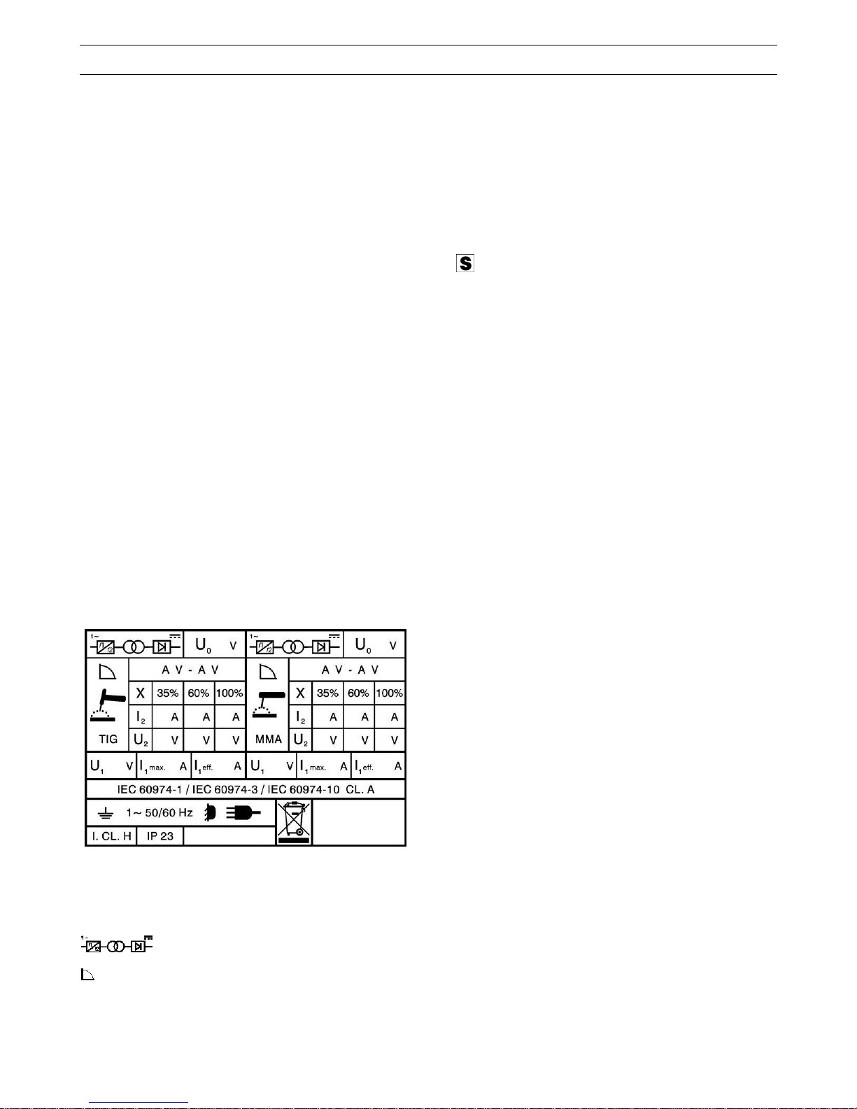
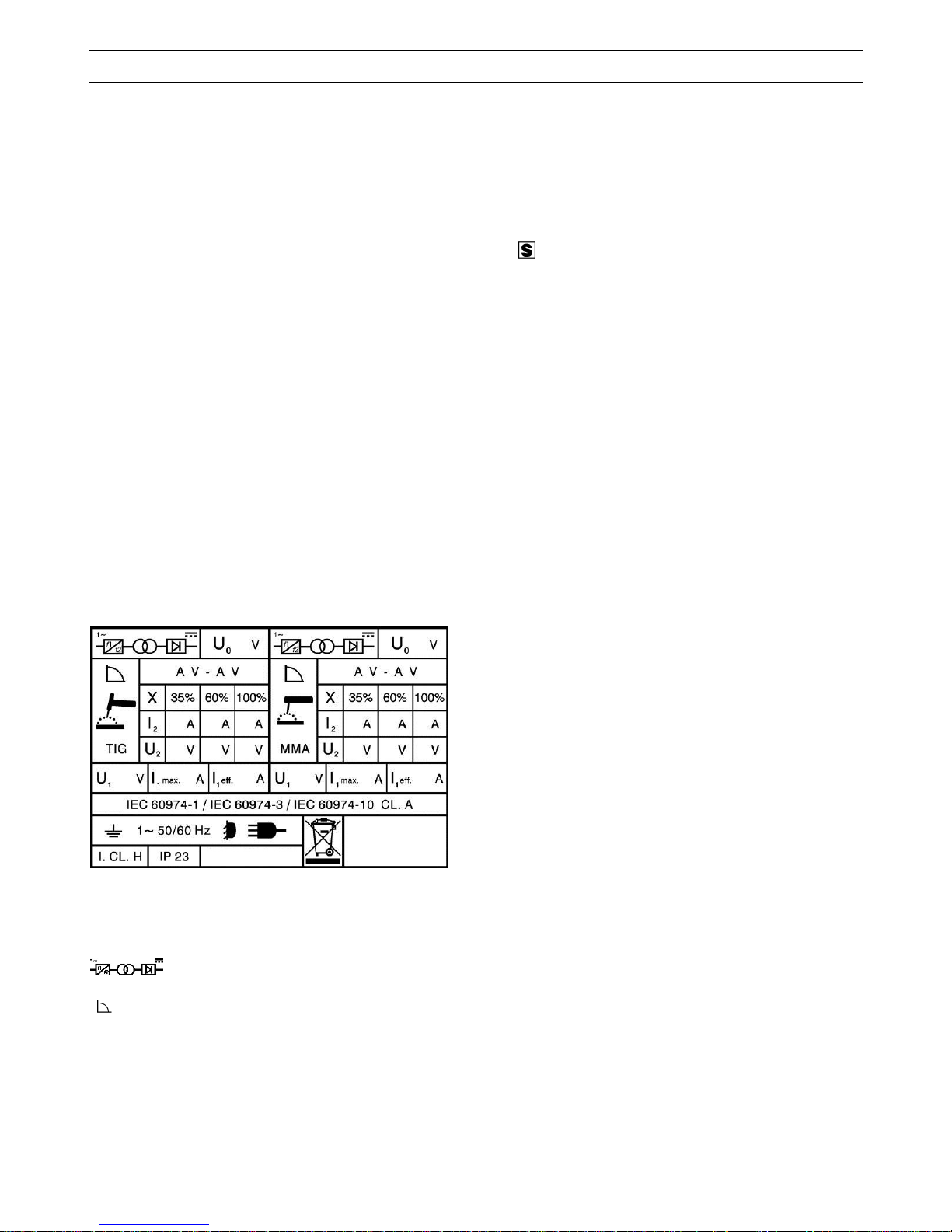
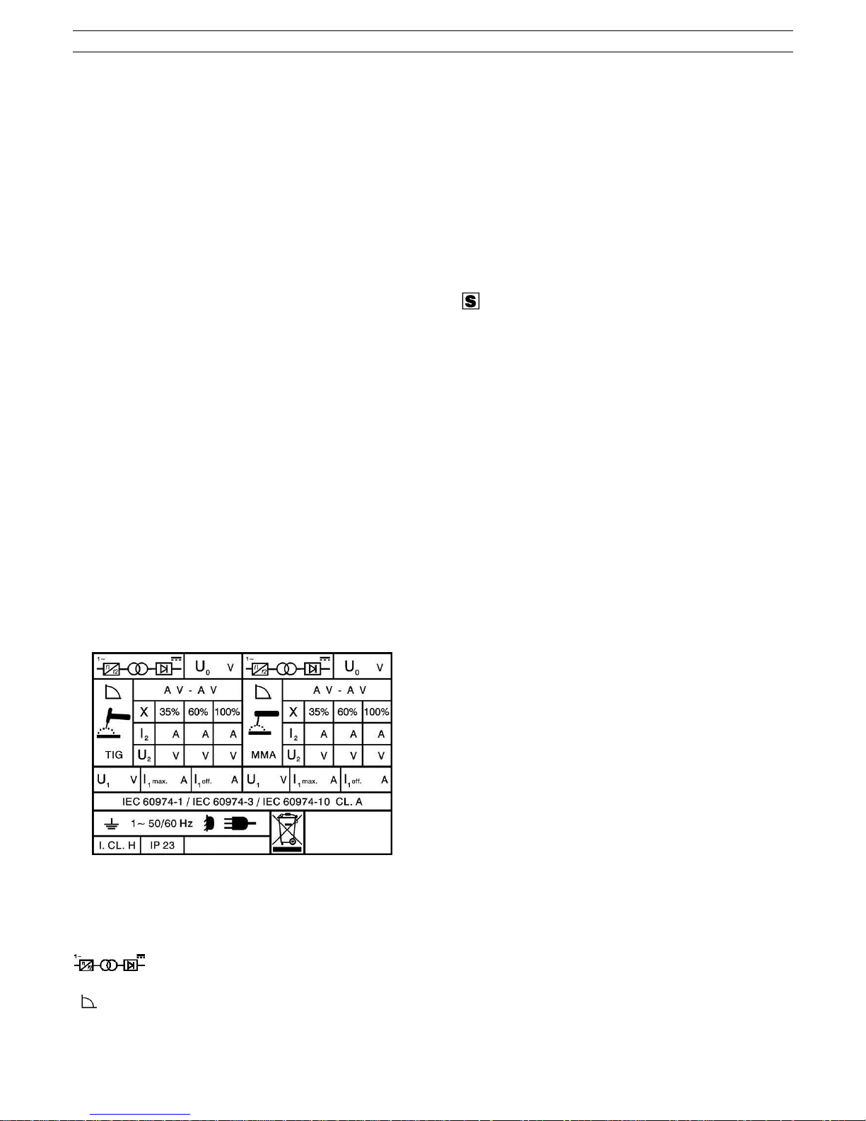
2.2. SPIEGAZIONE DEI DATI TECNICI RIPORTATI SULLA
TARGA DI MACCHINA
IEC60974-1 La saldatrice é costruita secondo
IEC60974-10 queste norme internazionali.
Cl. A Apparecchiatura per uso industriale e
professionale.
N° Numero di matricola da citare sempre per
qualsiasi richiesta relativa alla saldatrice.
Convertitore statico di frequenza monofase
trasformatore-raddrizzatore.
Caratteristica discendente.
MMA Adatto per saldatura con elettrodi rivestiti.
TIG Adatto per saldatura TIG.
U
0
Tensione a vuoto secondaria
X Fattore di servizio percentuale. % di 10 minuti in
cui la saldatrice può lavorare ad una
determinata corrente senza causare
surriscaldamenti.
I
2
Corrente di saldatura
U
2
Tensione secondaria con corrente I2
U
1
Tensione nominale di alimentazione
1~ 50/60Hz Alimentazione monofase 50 oppure 60 Hz
l
1
max. E’ il massimo valore della corrente assorbita.
l
1
eff. E’ il massimo valore della corrente effettiva
assorbita considerando il fattore di servizio.
IP23 Grado di protezione della carcassa che
omologa l’apparecchio per lavorare all’esterno
sotto la pioggia.
Idoneità ad ambienti con rischio accresciuto.
NOTE: La saldatrice è inoltre idonea a lavorare in ambienti
con grado di inquinamento 3. (Vedi IEC 664).
2.3. DESCRIZIONE DELLE PROTEZIONI
2.3.1 Protezione termica
Questo apparecchio è protetto da una sonda di temperatura
la quale, se si superano le temperature ammesse, impedisce
il funzionamento della macchina.
In queste condizioni il ventilatore continua a funzionare ed il
LED U si accende.
2.3.2 Protezione di blocco
Questa saldatrice è provvista di diverse protezioni che
fermano la macchina prima che subisca danni.
La segnalazione di fermo macchina è data dall’accensione
intermittente del LED rosso S.
L’accensione segnala:
1) Durante la fase di accensione, lo stato di alimentazione
della macchina.
2) Finita la fase di accensione, un’errata tensione di
alimentazione.
3) A macchina accesa, che la tensione è scesa sotto i 118V.
4) A macchina accesa, che la tensione di alimentazione
supera i 300V.
5) Se, durante la saldatura, la tensione supera i 300V.
Per ripristinare il funzionamento, verificare la tensione.
Quindi spegnere e riaccendere, dopo 5 secondi,
l’interruttore A9. Se l’inconveniente è stato risolto la
saldatrice ricomincerà a funzionare.
6) Se in saldatura a TIG la tensione a vuoto sul secondario
supera i 63 Vrms.
N.B. Se alla accensione la tensione di alimentazione è
inferiore a 170V nessun LED si accende e il ventilatore è
alimentato.
Se sul display compare la scritta E2 la macchina
necessita di un intervento tecnico.
2.3.3 Password
Quest’apparecchio è protetto contro l’uso da parte di
personale non autorizzato mediante la richiesta,
all’accensione, di una password.
Per attivare la funzione password, premere il tasto G e,
mantenendolo premuto, premere il tasto Y.
(Solo per art.165 Mantenerli premuti fino a quando sul
display T compare la sigla H2O, premere una volta il tasto Y
per far comparire la scritta PSS sul display T).
(Solo per art.164 Mantenerli premuti fino a quando sul
display T compare la scritta PSS).
Con la manopola R mettere su 1, confermare tenendo
premuto per 3sec. il tasto Y; all’ accensione della macchina
comparirà la scritta PSS sul display T e con la manopola R
inserire la password (visualizzata sul display T) e confermare
tenendo premuto il tasto Y.
3
Se il codice è errato, il generatore si blocca visualizzando la
scritta E72 e per reinserire nuovamente la password è
necessario spegnere e riaccendere il generatore.
Il codice password viene fornito insieme alla macchina e non
si può cambiare. Si consiglia di custodirlo separatamente e in
caso di smarrimento, contattare il servizio assistenza.
Il generatore esce dalla fabbrica con la funzione PSS su OFF.
2.3.4 Motogeneratori
Debbono avere un dispositivo di regolazione elettronico della
tensione, una potenza uguale o superiore a 4,5 kVA per art.
164 kVA e 6,5 kVA per art. 165 e non debbono erogare una
tensione superiore a 260V.
3. INSTALLAZIONE
Controllare che la tensione di alimentazione corrisponda alla
tensione indicata sulla targa dei dati tecnici della saldatrice.
La portata dell'interruttore magnetotermico o dei fusibili, in
serie alla alimentazione, deve essere uguale alla corrente I1
assorbita dalla macchina.
ATTENZIONE!: Le prolunghe fino a 30m devono essere
almeno di sezione 2,5 mm
2
.
3.1. MESSA IN OPERA
L'installazione della macchina deve essere fatta da personale
esperto. Tutti i collegamenti debbono essere eseguiti in
conformità alle norme vigenti e nel pieno rispetto della legge
antinfortunistica (norma CEI 26-10- CENELEC HD 427).
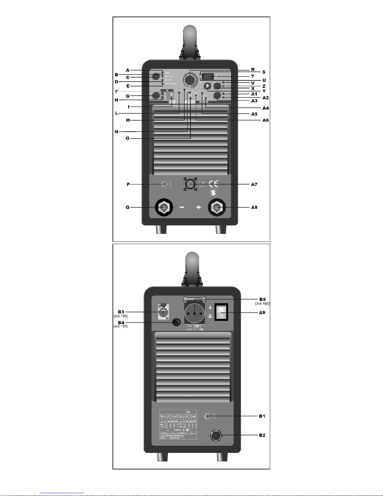
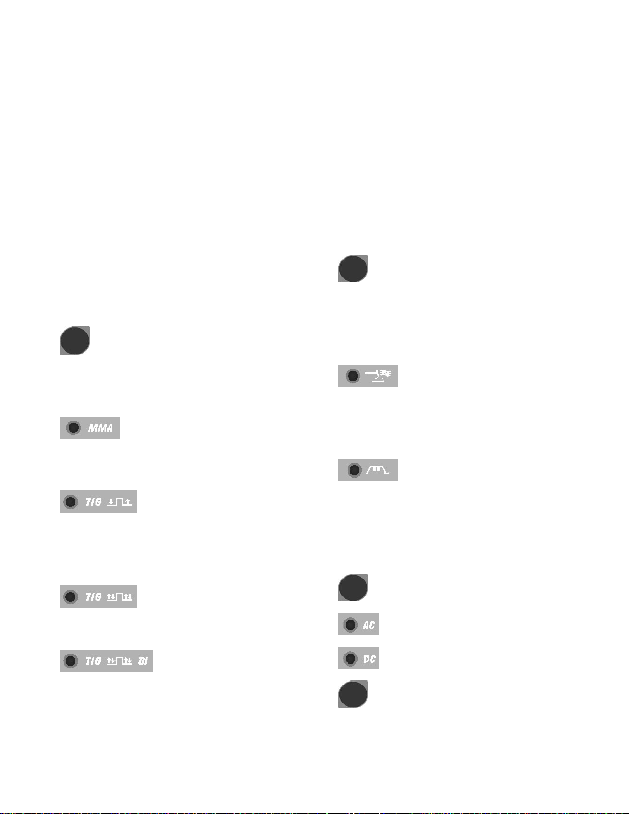
3.2 DESCRIZIONE DELL’APPARECCHIO (fig. 1 e 2)
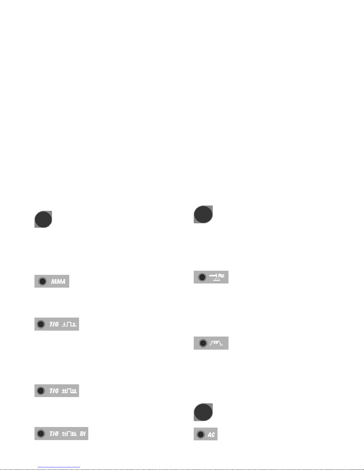
C - Selettore di procedimento e di modo
Tramite questo pulsante avviene la scelta del procedimento di
saldatura (Elettrodo o TIG) e del modo (2 tempi, 4 tempi e 4
tempi con due livelli di corrente).
A ogni pressione di questo pulsante si ottiene una nuova
selezione.
L'accensione dei LED in corrispondenza dei simboli visualizza
la Vostra scelta.
LED A - Saldatura ad elettrodo MMA.
Questa macchina può fondere tutti i tipi di elettrodi rivestiti
escluso il tipo cellulosico.
In questa posizione è abilitata a funzionare solo la manopola R
per la regolazione della corrente di saldatura.
LED B - Saldatura a TIG 2 tempi
(manuale)
Premendo il pulsante della torcia la corrente inizia ad
aumentare ed impiega un tempo corrispondente allo "slope
up" (LED L acceso) preventivamente regolato, per
raggiungere il valore regolato con la manopola R. Quando si
lascia il pulsante la corrente inizia a diminuire ed impiega un
tempo corrispondente allo "slope down" (LED A5 acceso)
preventivamente regolato, per ritornare a zero.
LED D - Saldatura a TIG 4 tempi
(automatico)
Questo programma differisce dal precedente perché sia
l'accensione che lo spegnimento vengono comandati
premendo e rilasciando il pulsante della torcia TIG.
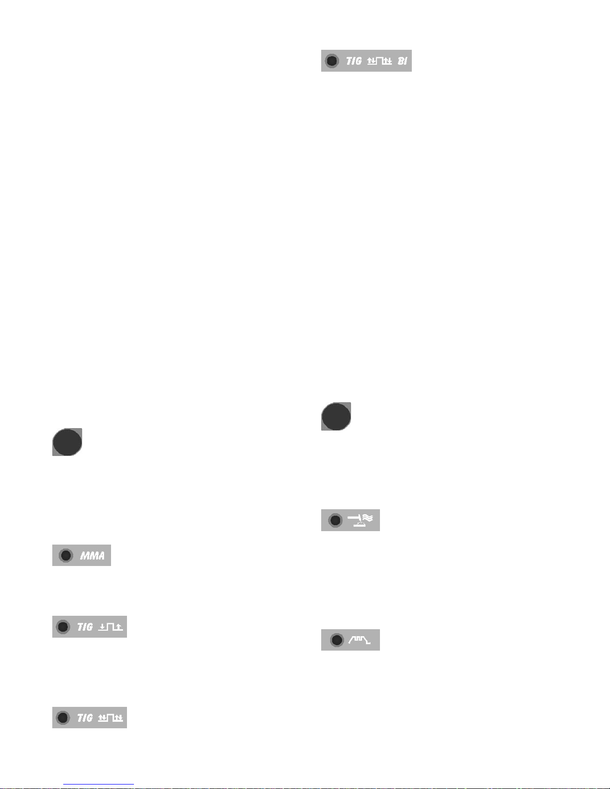
LED E - Saldatura a TIG 4 tempi
con due livelli di corrente (automatico bilevel)
Prima di accendere l'arco impostare i due livelli di corrente.
Primo livello: premere il tasto G fino ad accendere il LED M
e regolare la corrente principale con la manopola R.
Secondo livello: premere il tasto G fino ad accendere il LED
A6 e regolare la corrente con la manopola R.
Dopo l'accensione dell'arco la corrente inizia ad aumentare
ed impiega un tempo corrispondente allo "slope up" (LED L
acceso), preventivamente regolato, per raggiungere il valore
regolato con manopola R. Il LED M si accende e il display T
la visualizza.
Se durante la saldatura vi è la necessità di diminuire la
corrente senza spegnere l'arco (per esempio cambio del
materiale d'apporto, cambio di posizione di lavoro,
passaggio da una posizione orizzontale ad una verticale
ecc.…) premere e rilasciare immediatamente il pulsante
torcia, la corrente si porta al secondo valore selezionato, il
LED A6 si accende e M si spegne.
Per tornare alla precedente corrente principale ripetere
l'azione di pressione e di rilascio del pulsante torcia, il LED
M si accende mentre il LED A6 si spegne. In qualsiasi
momento si voglia interrompere la saldatura premere il
pulsante torcia per un tempo maggiore di 0,7 secondi poi
rilasciarlo, la corrente comincia a scendere fino al valore di
zero nel tempo di "slope down", preventivamente stabilito
(LED A5 acceso).
Durante la fase di "slope down", se si preme e si rilascia
immediatamente il pulsante della torcia, si ritorna in "slope
up" se questo è regolato ad un valore maggiore di zero,
oppure alla corrente minore tra i valori regolati.
N.B. il termine "PREMERE E RILASCIARE IMMEDIATAMENTE" fa riferimento ad un tempo massimo di 0,5 sec.
A3 - Selettore accensione con alta frequenza e
arco pulsato, on-off
Tramite questo pulsante avviene la scelta del tipo di
accensione (con alta frequenza o per contatto) e del modo
continuo o con arco pulsato. A ogni pressione di questo
pulsante si ottiene una nuova selezione.
L'accensione dei LED in corrispondenza dei simboli
visualizza la Vostra scelta.
LED A1 - Accensione con alta frequenza
o per contatto (solo TIG DC)
Quando il LED è spento per accendere l'arco premere il
pulsante torcia e toccare con l'elettrodo di tungsteno il pezzo
da saldare e rialzarlo. Il movimento deve essere deciso e
rapido.
Quando il LED è acceso per accendere l'arco premere il
pulsante torcia, una scintilla pilota di alta tensione/frequenza
accenderà l'arco.
LED A2 - Arco pulsato on-off
Quando il LED è acceso il modo arco pulsato è attivato.
Da 0,16 fino a 1,1Hz di frequenza di pulsazione il display T
visualizza alternativamente la corrente di picco (principale) e
la corrente di base
I LED M e N si accendono alternativamente; oltre 1,1Hz il
display T visualizza la media delle due correnti e i LED M e
N restano entrambi accesi.
Quando il LED è spento è attivo il modo continuo.
X - Selettore modo TIG AC o TIG DC
LED V - Saldatura TIG AC (corrente alternata)
4
LED Z - Saldatura TIG DC (corrente continua)
G - Selettore parametri di saldatura TIG
Premendo questo pulsante si illuminano in successione i LED.
dica il parametro che può essere regolato tramite
Attenzione si illumineranno solo i LED che si riferiscono al
modo di saldatura scelto; es. in saldatura TIG continuo non si
illuminerà il LED O che rappresenta la frequenza di
pulsazione.
Ogni LED in
la manopola R durante il tempo di accensione del LED stesso.
Dopo 5 secondi dall'ultima variazione il LED interessato si
spegne e viene indicata la corrente di saldatura principale e si
accende il corrispondente LED M.
LED F – Frequenza AC
Regola la ternata da 50 a 150Hz. frequenza della corrente al
LED H – Bilanciamento dell’onda.
Regola la pulizia da –8 a 0 o la penetrazione da 0 a 8.
LED I – Scelta del diametro dell’elettrodo in AC
Regola la partenza in funzione del diametro dell’elettrodo
LED L
Slope up. E' il tempo in cui la corrente, partendo dal minimo,
raggiunge il valore di corrente impostato. (0-10 sec.).
LED M
Corrente di saldatura principale.
LED N
Corrente di base in modo arco pulsato.
LED O
Frequenza di pulsazione da 0,16 a 250 Hz.
I tempi di base e di picco sono uguali.
LED A6
Secondo livello di corrente in modo bilevel.
LED A5
Slope down. E' il tempo in cui la corrente raggiunge il minimo
e lo spegnimento dell'arco. (0-10 sec.)
R - Manopola
Regola la corrente di saldatura LED M.
Inoltre in abbinamento del pulsante G è possibile:
ettrodo I
zione N
ulsazione O
l A6
- regolare la frequenza F
- regolare la pulizia o la penetrazione H
- regolare il diametro dell’el
- regolare lo "slope up" L
- regolare la corrente di base in pulsa
- regolare la frequenza di p
- regolare il secondo livello di corrente in bileve
- regolare lo "slope down" A5
- regolare il post gas A4.
LED S - Blocco saldatrice (vedi 2.3.2)
LED U - Protezione termica
Si accende quando l'operatore supera il fattore di servizio o
di intermittenza percentuale ammesso per la macchina e
blocca contemporaneamente l'erogazione di corrente.
N.B. In questa condizione il ventilatore continua a
raffreddare il generatore.
T - Display
Visualizza la corrente di saldatura e le impostazioni
selezionate con il p golate con la manopola R. ulsante G e re
Y - Selettore programmi in memoria.
Seleziona e memorizza i programmi.
La salda are nove
e di poterli richiamare
revemente questo pulsante viene visualizzato
il numero del programma successivo a quello in
tempo
ndi, si memorizzano i dati.
trice ha la possibilità di memorizz
programmi di saldatura P01…..P09
tramite questo pulsante. Inoltre è disponibile un programma
lavoro PL .
Selezione
Premendo b
sul display T
cui si sta lavorando. Se questo non è stato memorizzato la
scritta sarà lampeggiante, contrariamente sarà fissa.
Memorizzazione
Una volta selezionato il programma, premendo per un
maggiore di 3 seco
A conferma di questo, il numero del programma, visualizzato
sul display T, terminerà di lampeggiare.
A7 -CONNETTORE 10 POLI
A questo connettore vanno collegati i
seguenti com
art,
potenziometro,
andi remoti:
a) pedale,
b) torcia con pulsante di st
c) torcia con
d) torcia con up/down,
e) comando a distanza ecc.
LED A4
Post gas. Regola il tempo di uscita del gas al termine della
saldatura. (0-30 sec.).
5
P - Raccordo ¼ gas
Vi si connette il tubo gas della torcia di saldatura TIG.
Q
Morsetto di uscita negativo (-).
A8
Morsetto di uscita positivo (+).
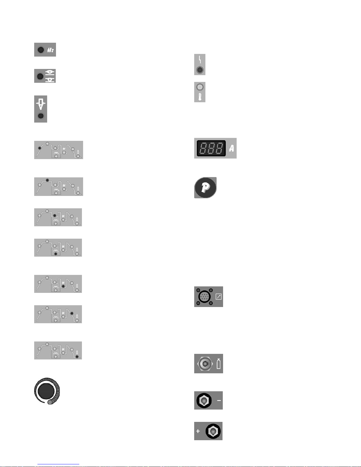
A9 - Interruttore
Accende e spegne la macchina.
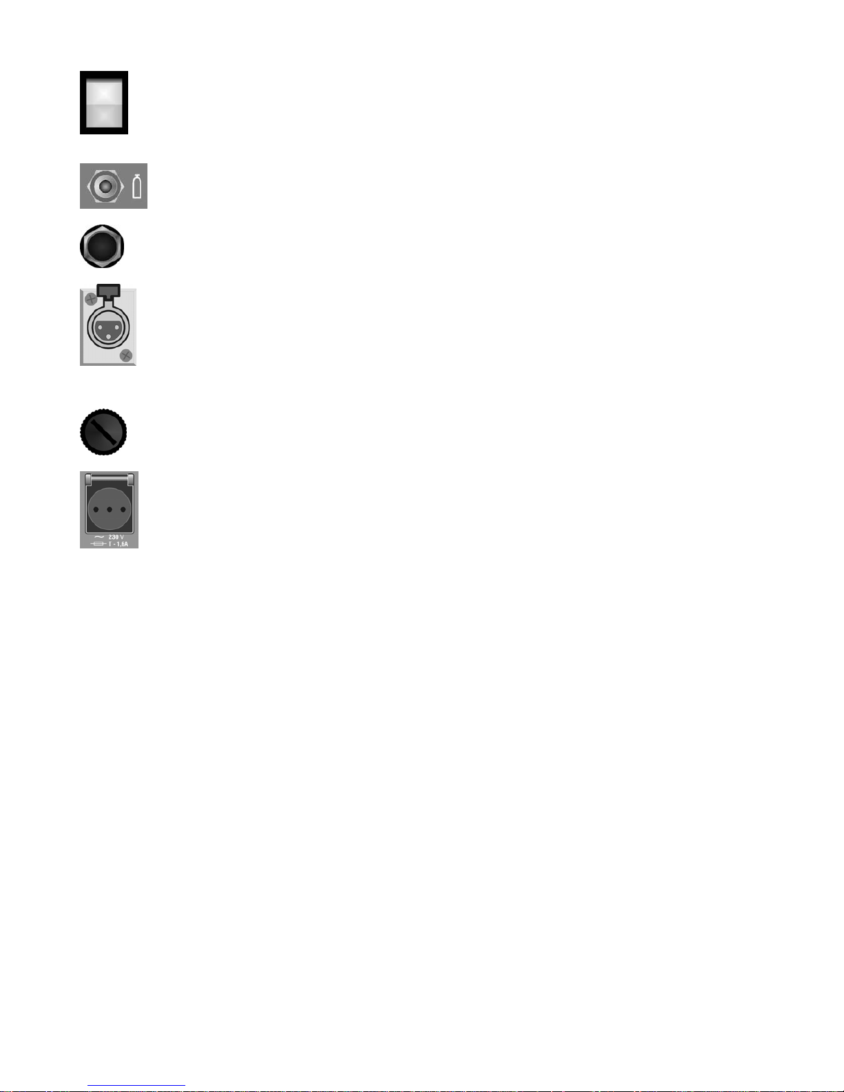
B1 - Raccordo ingresso gas
B2 - Cavo di alimentazione
B3 – Connettore (Solo per art.165)
Connettore a tre poli a cui va collegato il cavetto
del pressostato del gruppo di raffreddamento.
B4 – Portafusibile (Solo per art.165)
B5 – Presa (Solo per art.165)
A cui colleg
: 1,6.
.3. NOTE GENERALI
rima dell'uso di questa saldatrice leggere attentamente le
.4. SALDATURA DI ELETTRODI RIVESTITI (MMA)
Questa saldatrice è idonea alla saldatura di tutti i tipi di
quindi
are il gruppo di raffreddamento.
Attenzione: Potenza max: 360VA - Ampere
Non collegare utensili quali smerigliatrici o similari.
3
P
norme CEI 26/9 - CENELEC HD 407 e CEI 26.11 - CENELEC
HD 433 inoltre verificare l'integrità dell'isolamento dei cavi,
delle pinze porta elettrodi, delle prese e delle spine e che la
sezione e la lunghezza dei cavi di saldatura siano compatibili
con la corrente utilizzata.
3
elettrodi ad eccezione del tipo cellulosico (AWS 6010).
- Assicurarsi che l'interruttore A9 sia in posizione O,
collegare i cavi di saldatura rispettando la polarità richiesta dal
costruttore di elettrodi che andrete ad utilizzare e il morsetto
del cavo di massa al pezzo nel punto più vicino possibile alla
saldatura assicurandosi che vi sia un buon contatto elettrico.
- Non toccare contemporaneamente la torcia o la pinza porta
elettrodo ed il morsetto di massa.
- Accendere la macchina mediante l'interruttore A9.
- Selezionare, premendo il pulsante C, il procedimento MMA,
LED A acceso.
- Con procedimento MMA la ventola di raffreddamento è
sempre attiva.
- Regolare la corrente in base al diametro dell'elettrodo, alla
posizione di saldatura e al tipo di giunto da eseguire.
- Terminata la saldatura spegnere sempre l'apparecchio e
togliere l'elettrodo dalla pinza porta elettrodo.
3.5. SALDATURA TIG
Questa saldatrice è idonea a saldare con procedimento TIG
DC l'acciaio inossidabile, il ferro, il rame e con procedimento
TIG AC l’alluminio, l’ottone e il magnesio.
Collegare il connettore del cavo di massa al polo positivo (+)
della saldatrice e il morsetto al pezzo nel punto più vicino
possibile alla saldatura assicurandosi che vi sia un buon
contatto elettrico.
Collegare il connettore di potenza della torcia TIG al polo
negativo (-) della saldatrice.
Collegare il connettore di comando della torcia al connettore
A7 della saldatrice.
Collegare il raccordo del tubo gas della torcia al raccordo P
della macchina ed il tubo gas proveniente dal riduttore di
pressione della bombola al raccordo gas B1.
Solo per art.165 - Se si utilizza una torcia raffreddata ad
acqua utilizzare il gruppo di raffreddamento. Dopo avere
riempito di liquido refrigerante il serbatoio collegare la spina
del cavo rete del gruppo alla presa B5 della saldatrice,
quindi collegare il connettore maschio volante 3 poli del
gruppo al connettore B3. Accendere il gruppo di
raffreddamento utilizzando l’apposito interruttore (vedi
paragrafo 3.5.1).
Accendere la macchina mediante l'interruttore A9.
Non toccare parti sotto tensione e i morsetti di uscita quando
l'apparecchio è alimentato.
Alla prima accensione della macchina selezionare il modo
mediante i pulsanti C, X e A3 e i parametri di saldatura
mediante il tasto G e la manopola R come indicato al
paragrafo 3.2.
Con procedimento TIG la ventola di raffreddamento si attiva,
dopo 5 secondi si ferma per poi ripartire in fase di saldatura
fino al raffreddamento della macchina.
Il flusso di gas inerte deve essere regolato ad un valore (in
litri al minuto) di circa 6 volte il diametro dell'elettrodo.
Se si usano accessori tipo il gas-lens la portata di gas può
essere ridotta a circa 3 volte il diametro dell'elettrodo. Il
diametro dell'ugello ceramico deve avere una dimensione da
4 a 6 volte il diametro dell'elettrodo.
Normalmente il gas più usato è l'ARGON perché ha un costo
minore rispetto agli altri gas inerti, ma possono essere usate
anche miscele di ARGON con un massimo del 2%
IDROGENO per la saldatura dell'acciaio inossidabile e ELIO
o miscele di ARGON-ELIO per la saldatura del rame. Queste
miscele aumentano il calore il calore dell'arco in saldatura
ma sono molto più costose.
Se si usa gas ELIO aumentare litri al minuto fino a 10 volte il
diametro dell'elettrodo (Es. diametro 1,6 x10= 16 l/min. di
Elio).
Usare vetri di protezione D.I.N. 10 fino a 75A e D.I.N. 11 da
75A in poi.
3.5.1. GRUPPO DI RAFFREDDAMENTO (optional art.
560010)
Se si utilizza una torcia raffreddata ad acqua utilizzare il
gruppo di raffreddamento.
6

7
Per selezionare il modo di funzionamento del gruppo di
raffreddamento agire come segue:
1. Selezionare un qualsiasi procedimento TIG.
2. Premere il tasto Y e mantenendolo premuto premere il
tasto G. Mantenerli premuti fino a quando sul display T
compare la sigla H2O.
3. Selezionare il funzionamento tramite la manopola R
1 = Gruppo spento,
2 = Funzionamento in continuo,
3 = Funzionamento in automatico.
Per uscire dalla selezione, premere brevemente il tasto Y.
N.B. Per "Funzionamento automatico" si intende che il gruppo
di raffreddamento si mette in moto alla pressione del pulsante
torcia e smette di funzionare dopo circa 2 minuti dal rilascio
del pulsante torcia.
Attenzione! Se selezionata la saldatura in elettrodo, il
raffreddamento non è acceso e non è selezionabile. E'
normale che alla accensione della macchina il display T
visualizzi, in modo lampeggiante, la sigla H2O.
3.6. MEMORIZZAZIONE
E' possibile memorizzare solo dopo avere saldato.
Il pulsante Y, premuto brevemente, effettua una scelta;
premuto per un tempo maggiore di 3 secondi, effettua una
memorizzazione.
Ad ogni accensione, la macchina presenta sempre l'ultima
condizione utilizzata in saldatura.
3.6.1 Memorizzare i dati del programma PL
Utilizzando la macchina per la prima volta
Alla accensione della macchina il display visualizza la sigla PL
questa, dopo 5 secondi, scompare e viene visualizzata una
corrente di lavoro. Seguire le indicazioni dei paragrafi 3.2 e 3.5
quindi, per memorizzare i dati nel programma P01, procedere
nel seguente modo:
· Premere brevemente il pulsante Y comparirà la scritta P01
lampeggiante.
· Premere il pulsante Y per un tempo maggiore di 3 secondi
fino a che la sigla P01 smetta di lampeggiare, a questo punto
la memorizzazione è avvenuta.
· Ovviamente se invece di memorizzare nel programma P01 si
vuole memorizzare in un programma diverso si premerà il
pulsante Y in maniera breve tante volte quante necessarie per
visualizzare il programma desiderato. Alla riaccensione della
macchina viene visualizzato P01.
IL PULSANTE Y PREMUTO BREVEMENTE EFFETTUA
UNA SCELTA, PREMUTO PER UN TEMPO MAGGIORE DI
3 SECONDI EFFETTUA UNA MEMORIZZAZIONE.
3.6.2 Memorizzare da un programma libero
L'operatore può modificare e memorizzare un programma
scelto procedendo nel seguente modo:
· Premere il pulsante Y in modo breve e scegliere il numero di
programma desiderato.
I programmi liberi hanno la sigla lampeggiante.
· Premere i pulsanti C, X e A3 e scegliere il procedimento e il
modo di saldatura (paragrafo 3.2).
· Girare la manopola R ed impostare la corrente di saldatura.
Se è stato scelto il procedimento TIG, attivare il LED A4 (post
gas) tramite il pulsante G e regolare tramite la manopola R il
valore desiderato (paragrafo 3.2)
Se dopo queste regolazioni, necessarie per saldare, si
vogliono regolare i tempi di "slope" o altro agire come descritto
al paragrafo 3.2.
Eseguire una saldatura anche breve e decidere dove
memorizzare
Per memorizzare nel programma scelto precedentemente,
premere il pulsante Y per più di 3 secondi fino a che il numero
smette di lampeggiare.
Per memorizzare in un programma diverso, fare la scelta
premendo brevemente il pulsante Y quindi premere il
pulsante Y per più di 3 secondi.
3.6.3 Memorizzare da un programma memorizzato
Partendo da un programma già memorizzato l'operatore può
modificare i dati in memoria per aggiornare il programma
stesso o per trovare nuovi parametri da memorizzare in un
altro programma.
3.6.3.1 Aggiornare
· Dopo avere acceso la macchina selezionare i parametri da
modificare e modificarli.
· Eseguire una saldatura anche breve.
· Premere per un tempo maggiore di 3 secondi il tasto Y fino
alla conferma della memorizzazione (sigla del programma
da lampeggiante a continua).
3.6.3.2 Memorizzare in un nuovo programma
· Dopo avere acceso la macchina selezionare i parametri da
modificare e modificarli.
· Eseguire una saldatura anche breve.
· Premere brevemente il selettore Y fino alla visualizzazione
del programma da Voi desiderato.
· Premere di continuo il tasto Y fino alla conferma della
memorizzazione (sigla del programma da lampeggiante a
continua).
4. COMANDI A DISTANZA
Per la regolazione della corrente di saldatura a questa
saldatrice possono essere connessi i seguenti comandi a
distanza:
Art. 570008 Comando a pedale (usato in saldatura TIG)
Art. 535805 Torcia TIG UP/DOWN.
Art. 530330 +Art. 570006 (usato in saldatura MMA)
Art. 363307 Connessione per collegare la torcia e il
comando a pedale contemporaneamente.
Con questo accessorio l’Art. 570008 può essere utilizzato in
qualsiasi modo di saldatura TIG.
I comandi che includono un potenziometro regolano la
corrente di saldatura dal minimo fino alla massima
corrente impostata con la manopola R.
I comandi con logica UP/DOWN regolano dal minimo al
massimo la corrente di saldatura.
Le regolazioni dei comandi a distanza sono sempre attive
nel programma PL mentre in un programma memorizzato
non lo sono.
INSTRUCTION MANUAL FOR ARC WELDING MACHINES
IMPORTANT: READ THIS MANUAL AND THE “SAFETY
RULES” MANUAL CAREFULLY BEFORE INSTALLING,
USING, OR SERVICING THE WELDING MACHINE, PAYING
SPECIAL ATTENTION TO SAFETY RULES.
CONTACT YOUR DISTRIBUTOR IF YOU DO NOT FULLY
UNDERSTAND THESE INSTRUCTIONS.
1. PRECAUTIONS
This machine must be used for welding only. It must not be
used to defrost pipes.
It is also essential to pay special attention to the "SAFETY
RULES" Manual. The symbols next to certain paragraphs
indicate points requiring extra attention, practical advice or
simple information.
This MANUAL and the "SAFETY RULES" MANUAL must be
stored carefully in a place familiar to everyone involved in using
the machine. They must be consulted whenever doubts arise
and be kept for the entire lifespan of the machine; they will also
be used for ordering replacement parts.
2. GENERAL DESCRIPTIONS
2.1. SPECIFICATIONS
This welding machine is a constant current power source built
using INVERTER technology, designed to weld covered
electrodes (not including cellulosic) and for TIG procedures,
with contact starting and high frequency.
2.2. EXPLANATION OF THE TECHNICAL SPECIFICATIONS
LISTED ON THE MACHINE PLATE.
IEC60974-1 This welding machine is manufactured
IEC60974-10 according to these international standards.
Cl. A Machine for professional and industrial use
N°
Serial number, which must be indicated on any
type of request regarding the welding machine.
Single-phase static transformer-rectifier
frequency converter.
Drooping-characteristic.
MMA Suitable for welding with covered electrodes.
TIG Suitable for TIG welding.
U
0
Secondary open-circuit voltage.
X Duty cycle percentage. % of 10 minutes during
which the welding machine may run at a certain
current without overheating.
I
2
Welding current.
U
2
Secondary voltage with current I2.
U
1
Rated supply voltage.
1- 50/60Hz 50- or 60-Hz single-phase power supply
I1 max. This is the maximum value of the absorbed
current.
I
1
eff. This is the maximum value of the actual
current absorbed, considering the duty
cycle.
IP23 Protection grade of the housing, approving
the equipment as suitable for use outdoors
in the rain.
Suitable for hazardous environments.
NOTES: the welding machine has also been designed for
use in environments with a pollution rating of 3. (See IEC
664).
2.3. DESCRIPTION OF PROTECTIVE DEVICES
2.3.1 Thermal protection
This machine is protected by a temperature probe, which
prevents the machine from operating if the allowable
temperatures are exceeded. Under these conditions the fan
keeps running and the LED U lights.
2.3.2 Block protections
This welding machine is equipped with various safety
devices that stop the machine before it can suffer damage.
The stop of the machine is indicated by the flashing of the
red LED S and signals:
1) During the start-up phase, the power status of the
machine.
2) After the start-up phase, incorrect supply voltage.
3) With the machine running, that the voltage has fallen
below 118V.
4) With the machine running, that the supply voltage is
above 300V.
5) During welding, that the voltage exceeds 300V. To
restore operation, check the voltage. Then shut off the
A9 switch, wait 5 seconds, and switch it on again. If the
problem has been corrected, the welding machine will
begin operating again.
6) During TIG welding, that the secondary open-circuit
voltage exceeds 63 Vrms.
NOTE: if the supply voltage is below 170V at start-up,
no LED will light and the fan is powered.
If the message E2 appears on the display, the machine
requires technical intervention.
2.3.3 PASSWORD
This equipment is protected against the use on behalf of
unauthorized personnel through the request, on ignition, of
a password.
To activate the Password function, press the G key and
then, holding it down, press the Y key.
(Only for item 165: hold both keys down until the message
H2O is displayed on display T, then press the Y key once to
bring the message PSS to the T display).
(Only for item 164: hold both keys down until the message
PSS is displayed on display T).
By means of the knob R put on 1, confirm by pressing the
key Y for 3 seconds; when igniting the machine, the writing
PSS will appear on display T and with knob R insert the
password (displayed on display T) and confirm by holding
the Y key down.
If the code is incorrect, the generator will block, displaying
the writing ERR 72 and to insert the password again, it is
necessary to switch the generator off and on.
The password code is supplied together with the machine
and cannot be changed. It is recommended to keep it
8
separate, and in case of loss, contact the after-sales
assistance.
The generator leaves the factory with the PSS function on OFF.
2.3.4 Motor-driven generators
They must have an electronic regulator of the tension, a power
equal to or greater than 4,5 kVA, for art. 164, and 6,5 kVA, for
art. 165, and must not deliver a voltage greater than 260V.
3. INSTALLATION
Make sure that the supply voltage matches the voltage
indicated on the specification plate of the welding machine.
The capacity of the overload cut-out switch or fuses installed in
series with the power supply must be equivalent to the
absorbed current I1 of the machine.
WARNING! Extension cords of up to 30m must have a crosssection of at least 2.5 mm2.
3.1. START-UP
Only skilled personnel should install the machine. All
connections must be carried out according to current standards
and regulations, and in full observance of safety laws (CEI 2610 -CENELEC HD 427).
3.2. DESCRIPTION OF THE EQUIPMENT (pict. 1 and 2).
C – Procedure and mode selector switch
This push-button selects the welding procedure (MMA or TIG)
and mode (2-step, 4-step and 4-step with dual current level).
The selection changes each time the button is pressed.
The LEDs light next to the various symbols to display your
choice.
A LED – MMA (Manual Metal Arc) welding.
This machine can melt all types of coated electrodes, except for
cellulose.
In this position, only the R knob is enabled to adjust the welding
current.
B LED – 2-step TIG welding (manual)
When the torch trigger is pressed, the current begins to
increase over the previously set “slope up” time (L LED on),
until it reaches the value set by means of the R knob. When the
trigger is released, the current begins to drop over the
previously set “slope down” time (A5 LED on), until it goes back
to zero.
D LED – 4-step TIG welding (automatic)
This program differs from the previous one in that the arc is
both started and extinguished by pressing and releasing the
TIG torch trigger.
E LED – 4-step TIG welding with
dual current level (automatic dual level)
Set the two current levels before starting the arc.
First level: press the G key until the M LED lights, and adjust
the main current using the R knob.
Second level: press the G key until the A6 LED lights, and
adjust the current using the R knob.
After arc ignition, the current begins to increase over the
previously set “slope up” time (L LED on), until it reaches the
value set by means of the R knob. The M LED lights and
the display T shows the current.
Should it be necessary to reduce the current during
welding, without extinguishing the arc (for example when
changing the weld material or the working position, moving
from horizontal to standing position, etc.) press and
immediately release the torch trigger, the current will switch
to the second value selected, the A6 LED will light and the
M LED will go off.
To return to the previous main current, press and release
the torch trigger once again, the M LED will light and the A6
LED will go off. To stop welding at any time, simply hold
down the torch trigger for more than 0.7 seconds, then
release. The current begins to fall to zero within the
previously set "slope down" time interval (A5 LED on).
If you press and immediately release the torch trigger
during the "slope down" phase, you will revert to "slope up"
if this is set to any value greater than zero, or to the lesser
current value of those set.
N.B. the wording "PRESS AND IMMEDIATELY RELEASE"
refers to a maximum time of 0.5 seconds.
A3 – Selector switch for high frequency ignition
and pulsed arc mode, on-off
This push-button selects the ignition type (with high
frequency or by contact) and the continuous or pulsed arc
mode. The selection changes each time the button is
pressed.
The LEDs light next to the various symbols to display your
choice.
A1 LED – Ignition with high frequency or
by contact (only TIG DC mode).
When the LED is off, to start the arc, press the torch trigger
and touch the tungsten electrode to the workpiece, then lift
it. This move must be quick and sharp.
When the LED is on, to start the arc, press the torch trigger:
a high voltage/frequency pilot spark will start the arc.
A2 LED – Pulsed arc, on-off
When the LED is on, the pulsed arc mode is activated.
From a pulse frequency of 0.16 to 1.1Hz, the T display
alternately shows the peak (main) current and the base
current
The M and N LEDs light alternately: beyond 1.1 Hz the T
display shows the mean of the two currents and the M and
N LEDs both remain on.
When the LED is off, the continuous mode is activated.
X - TIG AC or TIG DC mode selector switch
V LED – AC TIG welding
Z LED – DC TIG welding
G – TIG welding parameters selector switch
Pressing this button will light the LEDs in sequence:
Warning: only those LEDs which refer to the chosen
welding mode will light; e.g. in continuous TIG welding the
LED O, representing the pulse frequency, will not light.
Each LED indicates the parameter, which may be adjusted
via the R knob during the lighting time of the LED.
9
5 seconds after the last variation, the LED involved will light off;
the main welding current will then be displayed and the
corresponding M LED will light.
F LED – AC frequency
Adjust the AC frequency from 50 to 150Hz.
H LED – Wave balance.
Adjust the cleaning from –8 to 0 or the penetration from 0 to 8.
LED I – Selection of the electrode diameter in AC
mode
Adjust the start-up according to the diameter of the electrode.
L LED
Slope up. This is the time during which the current, starting
from the minimum, reaches the set current value (0-10 sec.)
M LED
Main welding current.
N LED
Base current in pulsed arc mode.
O LED
Pulse frequency (0.16 to 250 Hz).
The base and peak times are the same.
A6 LED
Second level of current in dual level mode.
A5 LED
Slope down. This is the time during which the current reaches
its minimum value and the arc is extinguished (0-10 sec.).
A4 LED
Post gas. Adjusts the gas flow time at the end of welding (0-30
sec.).
R – Knob.
Adjusts the welding current – M LED.
In addition, combined with the G push-button, you may:
- adjust the frequency F
- adjust the cleaning or the penetration H
- adjust the diameter of the electrode I
- adjust the "slope up" L
- adjust the base pulse current N
- adjust the pulse frequency O
- adjust the second level of current in dual level A6
- adjust the "slope down" A5
- adjust the post gas A4
S LED – Welding machine block (see 2.3.2)
U LED – Thermal protection.
It lights when the operator exceeds the duty cycle or
percentage intermittence allowed for the machine and
simultaneously locks the current output.
N.B. Under this condition the fan goes on cooling the
power source.
T – Display
Displays the welding current and the settings which were
selected via the G push-button and adjusted via the R knob.
Y – Selector switch for programs in memory.
Selects and saves the programs in memory.
The welding machine can save nine welding programs
P01…..P09 and call them up via this button. A working
program PL is also available.
Selecting
When this push-button is pressed briefly, the T display
shows the program number next to the one in use. If this
has not been saved, the message will flash, otherwise it
remains steady.
Saving
Once the program has been selected, hold down for more
than 3 seconds to save the data in memory.
To confirm this, the program number on the T display will
stop flashing
A7 – 10-PIN CONNECTOR.
The following remote controls are to be connected to this
connector:
a) foot control,
b) torch with start button,
c) torch with potentiometer,
d) torch with up/down,
e) remote control, etc.
P – ¼ gas fitting.
This is where the gas hose of the TIG welding torch is to be
connected.
Q
Negative output terminal (-)
A8
10
Positive output terminal (+)
A9 – Switch.
Turns the machine on and off.
B1 – Gas intake fitting.
B2 – Power supply cable.
B3 – Connector (only for item 165)
Three-pin connector to which to connect the wire of the cooling
unit pressure switch.
B4 – Fuse holder (only for item 165)
B5 – Socket (only for item 165)
To which to connect the cooling unit.
Caution: Max. power: 360VA - Amps: 1.6. Do not connect tools
such as polishers or similar.
3.3. GENERAL NOTES
Before using this welding machine, carefully read the standards
CEI 26/9 - CENELEC HD 407 and CEI 26.11 - CENELEC HD
433. Also make sure the insulation of the cables, electrode
clamps, sockets and plugs are intact, and that the size and
length of the welding cables are compatible with the current
used.
3.4. MMA WELDING (MANUAL METAL ARC)
- This welding machine is suitable for welding all types of
electrodes, with the exception of cellulosic (AWS 6010)*.
- Make sure that the switch A9 is in position O, then connect
the welding cables, observing the polarity required by the
manufacturer of the electrodes you will be using; also connect
the clamp of the ground cable to the workpiece, as close to the
weld as possible, making sure that there is good electrical
contact.
- Do NOT touch the torch or electrode clamp simultaneously
with the earth clamp.
-Turn the machine on using the switch A9.
- Select the MMA procedure by pressing the button C: LED A
lit.
- In MMA procedure the cooling fan is always on.
- Adjust the current based on the diameter of the electrode, the
welding position and the type of joint to be made.
- Always remember to shut off the machine and remove the
electrode from the clamp after welding.
3.5. TIG WELDING
This welding machine is suitable for welding stainless steel,
iron, or copper using the TIG procedure in DC mode and
aluminium, brass and magnesium using the TIG procedure
in AC mode.
Connect the earth cable connector to the positive pole (+) of
the welding machine, and the clamp to the workpiece as
close as possible to the welding point, making sure there is
good electrical contact.
Connect the power connector of the TIG torch to the
negative pole (-) of the welding machine.
Connect the torch connector to the welding machine
connector A7.
Connect the torch gas hose fitting to the fitting P on the
machine, and the gas hose from the cylinder pressure
regulator to the gas fitting B1 on the rear panel.
Only for item 165 - If using a water-cooled torch, use the
cooling unit. After having filled the tank with coolant,
connect the plug of the mains cable to the socket B5 of the
welding machine, then connect the 3-pin male patch
connector to the connector B3. Turn on the cooling unit by
means of the apposite switch (see par. 3.5.1).
Turn on the machine by means of the switch A9.
Do not touch live parts and output terminals while the
machine is powered.
The first time the machine is turned on, select the mode
using the push-buttons C, X and A3 and the welding
parameters by means of the key G and the knob R
as
described in paragraph 3.2.
In TIG procedure the cooling fan starts working, after 5
seconds it stops for starting again to work during welding
process till the machine is cooled.
The flow of inert gas must be set to a value (in litres per
minute) approximately 6 times the diameter of the
electrode.
If you are using gas-lens type accessories, the gas
throughput may be reduced to approximately 3 times the
diameter of the electrode. The diameter of the ceramic
nozzle must be 4 to 6 times the diameter of the electrode.
The most commonly used gas is normally ARGON,
because it is less costly than other inert gases, but you may
also use blends of ARGON with a maximum of 2%
HYDROGEN for welding stainless steel, and HELIUM or
ARGON-HELIUM blends for welding copper.
These blends increase the heat of the arc while welding, but
are much more expensive.
If you are using HELIUM gas, increase the litters per minute
to 10 times the diameter of the electrode (Ex. diameter 1.6 x
10= 16 It./min of Helium).
Use D.I.N. 10 protective glasses for up to 75A, and D.I.N.
11 from 75A up.
3.5.1 Cooling unit (optional item 560010).
When using a water-cooled torch, use the cooling unit.
To select the cooling unit working mode, proceed as
follows:
1. Select any TIG procedure.
2. Press the key Y and while holding it down, press the
key G. Hold both keys down until the display T reads
H2O.
3. Select the working mode with the knob R.
1 = Unit off,
2 = Continuous operation,
3 = Automatic operation.
To exit the selection menu briefly press Y.
N.B. "Automatic operation" means that the cooling unit is
started when the torch button is pressed and stopped after
approximately 2 minutes from releasing the torch button.
Caution! If electrode welding is selected, cooling is not
active and cannot be selected. Upon machine power-on,
11

12
the display T may show the flashing message H2O.
3.6. SAVING
You may save parameters only after welding.
Pressing the push-button Y briefly makes a selection, while
holding it down for more than 3 seconds saves the data.
Each time it is turned on, the machine always shows the last
welding condition used.
3.6.1 Saving data from the PL program
Using the machine for the first time
When the machine is turned on, the display shows the symbol
PL; this disappears after 5 seconds, and a working current is
displayed. Follow the instructions in paragraphs 3.2 and 3.5,
then proceed as follows to save the data in the program P01:
• Briefly press the push-button Y, the message P01 will appear
flashing.
• Press push-button Y for more than 3 seconds, until the
symbol P01 stops flashing: at this point, the data have been
saved.
• Obviously, if you wish to save in a program other than P01,
you should briefly press the push-button Y as many times as
necessary to display the desired program. P01 will be displayed
the next rime the machine is turned on.
PRESSING THE Y PUSH-BUTTON BRIEFLY MAKES A
SELECTION, WHILE HOLDING IT DOWN FOR MORE THAN
3 SECONDS SAVES THE DATA.
3.6.2 Save from a free program
The operator may edit and save a selected program by
proceeding as follows:
• Press the push-button Y briefly and select the desired
program number.
• The symbol of free programs is flashing.
• Press the push buttons C, X and A3 and select the welding
procedure and mode (paragraph 3.2).
• Turn the knob R and set the welding current.
• If the TIG procedure has been selected, activate the LED A4
(post gas) by means of the push-button G, and set the desired
value via the knob R (paragraph 3.2.)
• If you wish to adjust the "slope" times or other parameters,
after making these adjustments which are necessary in order
to weld, follow the steps described in paragraph 3.2.
• Weld, even briefly, and decide where to save
• To save in the previously selected program, press the button
Y for more than 3 seconds, until the number stops flashing.
• To save in a different program, make your selection by briefly
pressing the push-button Y, then hold down the push button Y
for more than 3 seconds.
3.6.3. Save from a saved program
Beginning with a previously saved program, the operator may
edit the data in memory to update the program itself, or to find
new parameters to save in another program.
3.6.3.1 Update
• Alter turning on the machine, select the parameters to be
edited and edit them.
• Weld, even briefly.
• Hold down the Y button for more than 3 seconds, until the
save is confirmed (program symbol changes from flashing to
steady).
3.6.3.2 Save in a new program
• After turning on the machine, select the parameters to be
edited and edit them.
• Weld, even briefly.
• Briefly press the selector Y until the desired program is
displayed.
• Hold down the Y button until the save is confirmed
(program symbol changes from flashing to steady).
4. REMOTE CONTROLS
The following remote controls may be connected to this
machine to adjust the welding current:
Item 570008 Foot control (used in TIG welding)
Item 535805 TIG UP/DOWN Torch.
Item 530330+ltem 570006 (used in MMA welding)
Item 363307 Connection to simultaneously connect the
torch and the pedal control. With this accessory, item
570008 may be used in any TIG welding mode.
Remote controls that include a potentiometer regulate
the welding current from the minimum to the maximum
current set via the knob R.
Remote controls with UP/DOWN Iogic regulate the
welding current from the minimum to the maximum.
Remote control settings are always active in the PL
program, while they are not active in a saved program.
BEDIENUNGSANLEITUNG FÜR LICHTBOGENSCHWEISSMASCHINEN
WICHTIG:
VOR INSTALLATION UND GEBRAUCH DIESER
SCHWEISSMASCHINE BZW. VOR AUSFÜHRUNG VON
BELIEBIGEN WARTUNGSARBEITEN, DIESES HANDBUCH
UND DAS HANDBUCH “SICHERHEITSVORSCHRIFTEN
FÜR DEN GERÄTEGEBRAUCH” AUFMERKSAM LESEN.
DABEI IST DEN SICHERHEITSNORMEN BESONDERE
BEACHTUNG ZU SCHENKEN. BITTE WENDEN SIE SICH
AN IHREN DISTRIBUTOR, WENN IHNEN AN DIESER
ANLEITUNG ETWAS UNKLAR IST.
1. VORWORT
Diese Maschine darf nur zur Ausführung von Schweißarbeiten
verwendet werden. Sie darf nicht zum Enteisen von Rohren
benutzt werden.
Des Weiteren ist dem Handbuch, das die
Sicherheitsvorschriften enthält, größte Beachtung zu
schenken.
Die Symbole neben den einzelnen Paragraphen weisen auf
Situationen, die größte Aufmerksamkeit verlangen, Tipps oder
einfache Informationen hin.
Die beiden Handbücher sind sorgfältig an einem Ort
aufzubewahren, der allen Personen, die mit dem Gerät zu tun
haben, bekannt ist. Sie sind immer dann heranzuziehen, wenn
Zweifel bestehen. Die beiden Handbücher haben die Maschine
über ihre ganze Lebensdauer zu “begleiten” und sind bei der
Bestellung von Ersatzteilen heranzuziehen.
2. ALLGEMEINE BESCHREIBUNG
2.1. EIGENSCHAFTEN
Bei dieser Schweißmaschine handelt es sich um eine
Konstant-Gleichstromquelle mit INVERTER-Technologie, die
zum WIG-Schweißen mit umhüllten Elektroden
(Zelluloseumhüllungen ausgenommen) und mit Berührungsund Hochfrequenzzündung entwickelt wurde. Nicht zum
Entfrosten von Rohrleitungen verwenden.
2.2. ERLÄUTERUNG DER TECHNISCHEN DATEN
IEC60974-1 Die Schweißmaschine wurde nach diesen
IEC60974-10 internationale Normen gebaut.
Cl. A Maschine für den industriellen und den
professionellen Einsatz.
Nr. Seriennummer; sie muss bei allen Anfragen zur
Schweißmaschine stets angegeben werden.
Statischer Einphasen-Frequenzumrichter
Transformator-Gleichrichter.
Fallende Kennlinie.
MMA Geeignet zum Schweißen mit umhüllten
Elektroden.
WIG Geeignet zum WIG-Schweißen
13
U
0
Leerlaufspannung Sekundärseite
X Einschaltdauer. Die Einschaltdauer ist der auf
eine Spieldauer von 10 Minuten bezogene
Prozentsatz der Zeit, die das Gerät bei einer
bestimmten Stromstärke arbeiten kann, ohne
sich zu überhitzen.
I2 Schweißstrom.
U
2
Sekundärspannung bei Schweißstrom I2.
U
1
Bemessungsspeisespannung.
1~ 50/60Hz Einphasen-Stromversorgung 50 oder 60 Hz.
I1 max. Dies ist der Höchstwert der Stromaufnahme.
I1 eff. Dies ist der Höchstwert der effektiven
Stromaufnahme bei Berücksichtigung der
relativen Einschaltdauer.
IP23 Schutzart des Gehäuses, die bescheinigt, dass
das Gerät im Freien bei Regen betrieben
werden darf.
Geeignet zum Betrieb in Umgebungen mit
erhöhter Gefährdung.
ANMERKUNGEN: Das Gerät ist außerdem für den Betrieb in
Umgebungen mit Verunreinigungsgrad 3 konzipiert. (Siehe
IEC 664).
2.3. BESCHREIBUNG DER SCHUTZEINRICHTUNGEN
2.3.1 Thermischer Schutz
Dieses Gerät wird durch einen Temperaturfühler geschützt,
der, wenn die zulässigen Temperaturen überschritten werden,
den Betrieb der Maschine sperrt. In diesem Zustand bleibt der
Lüfter eingeschaltet und die LED U leuchtet auf.
2.3.2 Schutzverriegelungen
Diese Schweißmaschine verfügt über verschiedene
Schutzeinrichtungen, welche die Maschine ausschalten, bevor
sie Schaden nehmen kann.
Die Ausschaltung der Maschine wird durch das Blinken der
roten LED S signalisiert.
Das Aufleuchten signalisiert:
1) Beim Einschalten: die Speisung der Maschine.
2) Nach dem Einschalten: eine falsche Speisespannung.
3) Bei eingeschalteter Maschine: die Spannung ist unter 118 V
gesunken.
4) Bei eingeschalteter Maschine: die Speisespannung
überschreitet 300V.
5) Während des Schweißens: die Spannung überschreitet
300V. Zum Wiederherstellen der normalen
Betriebsbedingungen die Spannung prüfen. Dann den
Schalter A9 ausschalten und nach 5 Sekunden wieder
einschalten. Wenn das Problem behoben wurde, arbeitet
die Schweißmaschine wieder ordnungsgemäß.
6) Beim WIG-Schweissen die Leerlaufspannung auf
Sekundärseite überschreitet 63 Vrms.
Hinweis: wenn die Speisespannung beim Einschalten
weniger als 170 V beträgt, leuchtet keine LED auf und der
Lüfter ist gespeist.
Auf dem Display erscheint die Meldung E2 und es ist der
Eingriff eines Technikers erforderlich.
2.3.3 PASSWORT
Dieses Gerät ist gegen den Zugriff seitens nicht autorisierter
Personen durch Abfrage eines Passworts zum Zeitpunkt des
Einschaltens geschützt.
Zur Aktivierung der Passwort-Funktion die Taste G drücken,
gedrückt halten und die Taste Y drücken.
(Nur für art. 165: die Tasten gedrückt halten, bis auf dem
Display T das Kürzel H2O angezeigt wird. Die Taste Y einmal
drücken: auf dem Display T wird der Schriftzug PSS
angezeigt).
(Nur für art. 164: die Tasten gedrückt halten, bis auf dem
Display T das Kürzel PSS angezeigt wird).
Dann gehen Sie mit dem Bedienungsknopf R auf 1. Zum
Bestätigen für 3 Sekunden den Drucktaster Y gedrückt halten;
bei Einschalten der Maschine erscheint die Meldung PSS am
Display T, mit dem Bedienungsknopf R das Passwort
eingeben (am Display T angezeigt) und zum Bestätigen die
Taste Y gedrückt halten.
Wenn der Code falsch ist, bleibt der Generator stehen und es
erscheint die Meldung ERR 72. Um neuerlich das Passwort
einzugeben muss man den Generator aus- und wieder
einschalten.
Der Passwort-Code wird gemeinsam mit der Maschine
geliefert und kann nicht verändert werden. Es wird empfohlen,
diesen separat aufzubewahren. Im Fall eines Verlustes ist der
Kundendienst zu kontaktieren. Bei der Auslieferung des
Generators steht die Funktion PSS auf OFF.
2.3.4 Generator-Aggregat
Seine Leistung muss größer oder gleich 4,5 kVA (Einphasen)
für Typ 164 und 6,5 kVA (Einphasen) für Typ 165 sein und es
darf keine Spannung von mehr als 260 V abgeben und darf
über eine elektronische Spannungregulierungsvorrichtung
verfügen.
3. INSTALLATION
Sicherstellen, dass die Speisespannung der auf dem
Leistungsschild der Schweißmaschine angegebenen
Bemessungsspannung entspricht.
Der Bemessungsstrom des in Reihe mit der Speisung
geschalteten thermomagnetischen Schalters oder der
Sicherungen muss gleich dem von der Maschine
aufgenommenen Strom I1 sein.
ACHTUNG! Die Verlängerungen bis 30 m müssen einen
Querschnitt von mindestens 2,5 mm
2
haben.
3.1. INGANGSETZEN
Die Installation der Maschine muss durch Fachpersonal
erfolgen. Alle Anschlüsse müssen nach den geltenden
Bestimmungen und unter strikter Beachtung der
Unfallverhütungsvorschriften ausgeführt werden (Norm CEI
26-10 CENELEC HD 427).
3.2 BESCHREIBUNG DES GERÄTS (Abb. 1 und 2)
C – Schweißverfahren- und Betriebsarten-
Wahlschalter
Mit diesem Drucktaster wählt man das Schweißverfahren
(Elektroden- oder WIG-Schweißen) und die Betriebsart (2Takt, 4-Takt und 4-Takt mit Zweiwertschaltung).
Jede Betätigung dieses Drucktasters bewirkt eine neue
Einstellung.
Die von Ihnen getroffene Wahl wird durch das Aufleuchten der
LEDs neben den jeweiligen Symbolen angezeigt.
A – LED Elektrodenschweißen (MMA)
Diese Maschine kann alle Arten von Elektroden mit Ausnahme
von Elektroden mit Zelluloseumhüllung schmelzen.
In dieser Position ist nur der Regler R für die Einstellung des
Schweißstroms freigegeben.
B – LED WIG-Schweißen – 2-Takt
(Handbetrieb)
Drückt man den Brennertaster, steigt der Strom in der zuvor
eingestellten Zeit "slope up" an (LED L leuchtet), bis der mit
dem Regler R eingestellte Wert erreicht wird. Löst man den
Brennertaster, sinkt der Strom in der zuvor eingestellten Zeit
“slope down” (LED A5 leuchtet) auf den Wert 0.
D – LED WIG-Schweißen – 4-Takt
(Automatikbetrieb)
Dieses Programm unterscheidet sich von dem vorherigen
darin, dass sowohl die Zündung als auch das Löschen durch
Betätigen und Lösen des WIG-Brennertasters gesteuert
werden.
E – LED WIG-Schweißen mit
Zweiwertschaltung – 4-Takt (Bilevel-Automatikbetrieb)
Vor dem Zünden des Lichtbogens müssen die zwei
verschiedenen Schweißströme eingestellt werden: Erste Stufe:
den Drucktaster G drücken, bis die LED M aufleuchtet, und
dann den Hauptstrom mit Regler R einstellen.
Zweite Stufe: den Drucktaster G drücken, bis die LED A6
aufleuchtet, und dann den Hauptstrom mit Regler R einstellen.
Nach dem Zünden des Lichtbogens steigt der Strom in der
zuvor eingestellten Zeit “slope up” an (LED L leuchtet), bis der
mit dem Regler R eingestellte Wert erreicht ist. Die LED M
leuchtet auf und das Display T zeigt den Wert an.
Wenn während des Schweißens das Erfordernis besteht, den
Strom zu senken, ohne den Lichtbogen zu löschen (z.B.
Wechsel des Schweißzusatzes, Wechsel der Arbeitsstellung,
Übergang von einer horizontalen Lage in eine vertikale usw.
…), muss man den Brennertaster drücken und wieder
loslassen: der Strom sinkt dann auf den zweiten gewählten
Wert, die LED A6 leuchtet auf und die LED M erlischt.
Um zum vorherigen Hauptstrom zurückzukehren, muss man
den Brennertaster erneut drücken und wieder loslassen: die
LED M leuchtet auf und die LED A6 erlischt. Wenn man den
Schweißprozess unterbrechen will, muss man den
Brennertaster für eine Dauer von mehr als 0,7 Sekunden
drücken und dann wieder loslassen: der Strom sinkt dann
innerhalb des Zeitintervalls „slope down“, das zuvor festgelegt
wurde, bis auf den Wert 0 (LED A5 leuchtet).
Wenn man während des „slope down“ den Brennertaster
drückt und sofort wieder löst, kehrt man entweder zum „slope
up“, wenn dessen Wert größer Null ist, oder zum niedrigeren
der eingestellten Stromwerte zurück.
HINWEIS: Mit dem Ausdruck „DRÜCKEN UND SOFORT
WIEDER LÖSEN“ ist eine Betätigungsdauer von maximal 0,5
Sekunden gemeint.
A3 –On-Off-Wahlschalter für Hochfrequenz-
Zündung und Impulsschweißen
Mit diesem Wahlschalter wählt man das Zündverfahren (HFoder Berührungszündung) und die Betriebsart Konstantstromoder Impulsschweißen. Jede Betätigung dieses Drucktasters
bewirkt eine neue Einstellung.
Die von Ihnen getroffene Wahl wird durch das Aufleuchten der
LEDs neben den jeweiligen Symbolen angezeigt.
A1 – LED Hochfrequenz- oder
Berührungszündung (nur WIG DC)
Wenn diese LED nicht leuchtet, muss man zum Zünden des
Lichtbogens den Brennertaster drücken, mit der WolframElektrode das Werkstück berühren und die Elektrode wieder
anheben. Diese Bewegung muss entschieden und rasch
ausgeführt werden.
Wenn diese LED leuchtet, muss man zum Zünden des
Lichtbogens den Brennertaster drücken: ein Zündfunke hoher
Spannung/Frequenz zündet den Lichtbogen.
A2 – LED Impulsschweißen on-off
Diese LED leuchtet auf, wenn die Betriebsart Impulsschweißen
eingeschaltet ist.
Bei einer Impulsfrequenz von 0,16 bis 1,1 Hz zeigt das Display
T abwechselnd den Spitzenstrom (Hauptstrom) und den
Grundstrom an.
Die LEDs M und N leuchten abwechselnd auf; jenseits von 1,1
Hz zeigt das Display T den Mittelwert der beiden Ströme an
und die LEDs M und N leuchten beide ständig. Leuchtet diese
LED nicht auf, ist die Betriebsart Konstantstromschweißen
eingeschaltet.
14

X – WIG DC oder WIG AC Betriebsarten-
Wahlschalter
V - LED WIG-AC-Schweissen (Wechselstrom)
Z - LED WIG-DC-Schweissen (Gleichstrom)
G – Wahlschalter für die WIG-Schweißparameter
Drückt man diesen Drucktaster, leuchten nacheinander
folgende LEDs auf:
Achtung: es leuchten nur die dem gewählten Schweißprozess
entsprechenden LEDs auf; beim WIG-Konstantstromverfahren
leuchtet zum Beispiel nicht die LED O auf, welche die
Impulsfrequenz repräsentiert.
Die einzelnen LEDs zeigen den Parameter an, der mit dem
Regler R innerhalb des Zeitraums, in dem die LED leuchtet,
eingestellt werden kann.
5 Sekunden nach der letzten Änderung erlischt die betreffende
LED und es wird der Hauptschweißstrom angezeigt; außerdem
leuchtet die zugehörige LED M auf.
F - LED AC Frequenz
Sie regelt die Frequenz für den Wechselstrom von 50 bis
150Hz.
H - LED Balanceregelung.
Sie regelt die Reinigungswirkung von –8 bis 0 oder die
Einbrandwirkung von 0 bis 8.
I – LED Wahl von der Elektrodendurchmesser beim
AC-Schweissen
Sie regelt der Start in Abhängigkeit vom
Elektrodendurchmesser
L - LED
Slope up. Dies ist das Zeitintervall, in dem der Strom
ausgehend vom Mindestwert den eingestellten
Schweißstromwert erreicht. (0-10 s)
M - LED
Hauptschweißstrom
N - LED
Grundstrom in der Betriebsart Impulsschweißen
O - LED
Impulsfrequenz (0,16 bis 250 Hz)
Impulszeit und Grundzeit sind gleich.
A6 - L ED
Zweite Schweißstromstufe in der Betriebsart Bilevel
A5 - LED
Slope down. Dies ist das Zeitintervall, in dem der Strom den
Mindestwert erreicht und der Lichtbogen gelöscht wird. (0-10s)
A4 - L ED
Post gas. Zum Einstellen der Dauer des Gasaustritts nach
Abschluss der Schweißung. (0-30 s)
R - Regler
Für die Einstellung des Schweißstroms LED M.
Außerdem bestehen in Verbindung mit Drucktaster G folgende
Möglichkeiten:
- Einstellung der Frequenz F
- Einstellung der Reinigungswirkung oder der
Einbrandwirkung H
- Einstellung des Elektrodendurchmessers I
- Einstellung der Stromanstiegszeit "slope up" L
- Einstellung des Grundstroms für die Betriebsart
Impulsschweißen N
- Einstellung der Impulsfrequenz O
- Einstellung der zweiten Schweißstromstufe für die Betriebsart
Bilevel A6
- Einstellung der Stromabfallszeit "slope down" A5
- Einstellung der Post-gas-Zeit A4
S – LED für die Verriegelungsanzeige (siehe 2.3.2)
U – LED thermischer Schutz
Diese LED leuchtet auf, wenn der Schweißer die zulässige
Einschaltdauer oder die zulässige Dauer des Aussetzbetriebs
für die Maschine überschreitet; zugleich wird die Stromabgabe
gesperrt.
HINWEIS. In diesem Zustand kühlt der Lüfter weiterhin die
Stromquelle.
T -Display
Anzeige des Schweißstroms und der mit dem Drucktaster G
und dem Regler R vorgenommenen Einstellungen.
Y - Wahlschalter
Wahl und Speicherung der Programme.
Die Schweißmaschine kann neun Programme (P01 bis P09)
abspeichern, die mit diesem Drucktaster aufgerufen werden
können. Außerdem ist ein Arbeitsprogramm PL verfügbar.
Wahl
Betätigt man diesen Drucktaster kurz, zeigt das Display T die
Nummer des Programms an, das auf das Programm folgt, mit
dem gerade gearbeitet wird. Wenn dieses Programm nicht
gespeichert wurde, blinkt die Anzeige; andernfalls ist die
Anzeige permanent.
Speicherung
Drückt man nach Wahl des Programms den Drucktaster für
mehr als 3 Sekunden, werden die Daten gespeichert.
Zur Bestätigung hört die Anzeige der Programmnummer auf
dem Display T auf zu blinken.
A7 – 10-POLIGE STECKDOSE
An diese Steckdose können folgende
15

Fernregler angeschlossen werden:
a) Fußregler
b) Brenner mit Start-Taster
c) Brenner mit Potentiometer
d) Brenner mit UP/DOWN-Steuerung
e) Fernbedienung usw. ...
P – Anschluss (¼ Gas).
Hier wird der Gasschlauch des WIG-Brenners angeschlossen.
Q
Ausgangsklemme Minuspol (-)
A8
Ausgangsklemme Pluspol (+)
A9 – Schalter
Zum Ein- und Ausschalten der Maschine.
B1 –Gas-Speiseanschluss
B2 – Speisekabel
B3 – Steckvorrichtung (nur für art. 165)
Dreipolige Steckvorrichtung für den Anschluss des Kabels des
Druckschalters des Kühlaggregats.
B4 – Sicherungshalter (nur für art. 165)
B5 - Steckdose (nur für art. 165)
Für den Anschluss des Kühlaggregats.
Achtung: Max. Leistung: 360VA - Ampere: 1,6. Keine
Werkzeugmaschinen wie Schleifmaschinen o.ä. anschließen.
3.3. ALLGEMEINE HINWEISE
Vor Gebrauch dieser Schweißmaschine die Normen CEI 26/9 CENELEC HD 407 und CEI 26.11 - CENELEC HD 433
aufmerksam lesen; außerdem sicherstellen, dass die
Isolierung der Leitungen, der Elektrodenspannzange, der
Steckdosen und der Stecker intakt ist und dass Querschnitt
und Länge der Schweißleitungen mit dem verwendeten Strom
verträglich sind.
3.4. SCHWEISSEN MIT UMHÜLLTEN ELEKTRODEN (MMA)
- Diese Schweißmaschine ist zum Schweißen mit allen Arten
von umhüllten Elektroden mit Ausnahme von Elektroden
mit Zelluloseumhüllungen (AWS 6010) geeignet.
- Sicherstellen, dass sich Schalter A9 in Schaltstellung O
befindet. Dann die Kabel unter Beachtung der vom
Hersteller der verwendeten Elektroden verlangten Polung
anschließen. Außerdem die Klemme des Massekabels an
das Werkstück so nahe wie möglich an der Schweißstelle
anschließen und sicherstellen, dass ein guter elektrischer
Kontakt gegeben ist.
- Niemals gleichzeitig den Brenner oder die
Elektrodenspannzange und die Masseklemme berühren.
- Die Maschine mit dem Schalter A9 einschalten.
- Durch Drücken von Drucktaster C das Schweißverfahren
MMA wählen; die LED A leuchtet.
- Bei MMA Verfahren das Lüfterrad ist immer laufend.
- Den Strom in Abhängigkeit vom Elektrodendurchmesser,
der Schweißposition und der auszuführenden Art von
Schweißverbindung einstellen.
- Nach Abschluss des Schweißvorgangs stets das Gerät
ausschalten und die Elektrode aus der
Elektrodenspannzange nehmen.
3.5. WIG-SCHWEISSEN
Diese Schweißmaschine ist zum Schweißen von rostfreiem
Stahl, Eisen und Kupfer mit dem DC-WIG-Verfahren und von
Aluminium, Messing und Magnesium mit dem AC-WIGVerfahren geeignet
Den Steckverbinder des Massekabels an den Pluspol (+) der
Schweißmaschine und die Klemme an das Werkstück
möglichst nahe bei der Schweißstelle anschließen;
sicherstellen, dass ein guter elektrischer Kontakt gegeben ist.
Den WIG-Brenner an den Minuspol (-) der Schweißmaschine
anschließen.
Den Steckverbinder der Steuerleitung des Schlauchpakets an
die Steckdose A7 der Schweißmaschine anschließen.
Den Anschluss des Gasschlauchs des Schlauchpakets an den
Anschluss P der Maschine und den vom Druckminderer der
Gasflasche kommenden Gasschlauch an den Gasanschluss
B1 anschließen.
Nur für art. 165 - Für einen wassergekühlten Brenner das
Kühlaggregat verwenden.
Die Kühlflüssigkeit einfüllen und den Netzstecker in die
Steckdose B5 der Schweißmaschine einstecken. Dann den
dreipoligen fliegenden Stecker an die Steckvorrichtung B3
anschließen. Die Kühlflüssigkeit mit dem dazu bestimmten
Schalter einschalten (Siehe Abschnitt 3.5.1).
Die Maschine mit dem Schalter A9 einschalten.
Keinesfalls spannungführende Teile und die
Ausgangsklemmen berühren, wenn das Gerät eingeschaltet
ist.
Beim ersten Einschalten der Maschine mit den Drucktastern C,
X und A3 das Verfahren wählen; außerdem die
Schweißparameter mit der Taste G und dem Regler R wie in
Abschnitt 3.2 beschrieben einstellen.
Bei WIG Verfahren das Lüfterrad aktiviert sich, nach 5
Sekunden anhält sich und dann, bei Schweißen, es bis die
Kühlung der Schweißmaschine abstartet.
Der Shutzgasfluß muss auf einen Wert (Liter/Minute)
eingestellt werden, der ungefähr dem Sechsfachen des
Elektrodendurchmessers entspricht.
Bei Verwendung von Zubehör wie Gaslinsen kann die GasLiefermenge auf ungefähr das Dreifache des
Elektrodendurchmessers gesenkt werden. Der Durchmesser
der Keramikdüse muss dem Vier- bis Sechsfachen des
Elektrodendurchmessers entsprechen.
Normalerweise wird als Gas ARGON verwendet, da es
preisgünstiger ist als andere Inertgase. Es können jedoch auch
Gemische mit ARGON als Grundgas und einem Anteil von
maximal 2% WASSERSTOFF zum Schweißen von rostfreiem
Stahl bzw. HELIUM und Gemische aus ARGON - HELIUM
zum Schweißen von Kupfer verwendet werden. Diese
Gemische erhöhen die Temperatur des Lichtbogens beim
Schweißen, sind aber sehr teuer.
Bei Verwendung von HELIUM muss die Liefermenge
(Liter/Minute) bis auf das Zehnfache des
16

17
Elektrodendurchmessers erhöht werden (Beispiel:
Durchmesser 1,6 x 10= 16 l/min Helium).
Augenschutzgläser DIN 10 bis 75 A und DIN 11 ab 75 A
aufwärts verwenden.
3.5.1 Kühlaggregat (Art. 560010 optional).
Bei Gebrauch eines wassergekühlten Brenners das
Kühlaggregat verwenden.
Zur Auswahl der Betriebsart des Kühlaggregats auf folgende
Weise vorgehen:
1. Ein beliebiges WIG-Schweißverfahren auswählen.
2. Die Taste Y drücken, gedrückt halten und die Taste G
drücken. Beide Tasten gedrückt halten, bis auf dem
Display T das Kürzel H2O angezeigt wird.
3. Die Funktionsweise über den Regler R auswählen:
1 = Aggregat ausgeschaltet,
2 = Dauerbetrieb,
3 = Automatikbetrieb.
Zum Verlassen der Wahlfunktion kurz den Taster Y
drücken.
HINWEIS: „Automatikbetrieb“ bedeutet, dass das
Kühlaggregat bei Betätigung des Brennertasters anläuft und
rund 2 Minuten nach Loslassen des Brennertasters wieder
abschaltet.
Achtung! Wenn das Elektrodenschweißen gewählt wurde, ist
die Kühlung nicht eingeschaltet und kann folglich auch nicht
gewählt werden. Es ist normal, dass im Moment der
Einschaltung der Maschine auf dem Display T die blinkende
Anzeige „H2O“ erscheint.
3.6. SPEICHERUNG
Das Speichern ist erst nach dem Schweißen möglich.
Durch kurze Betätigung von Drucktaster Y nimmt man die
Wahl vor; durch Betätigung von mehr als 3 Sekunden
veranlasst man die Speicherung.
Bei jeder Einschaltung befindet sich die Maschine stets in dem
Zustand, in dem sie bei der letzten Schweißung verwendet
wurde.
3.6.1. Speichern der Daten von Programm PL
Bei erstmaliger Verwendung der Maschine.
Beim Einschalten der Maschine erscheint auf dem Display das
Kürzel PL. Nach 5 Sekunden erlischt diese Anzeige und es
wird ein Arbeitsstrom angezeigt. Die Anweisungen in den
Abschnitten 3.2 und 3.5 befolgen und dann zum Speichern der
Daten in Programm P01 wie folgt vorgehen:
• Kurz Drucktaster Y drücken: es erscheint die blinkende
Anzeige P01.
• Drucktaster Y für mehr als 3 Sekunden drücken, bis die
Anzeige P01 zu blinken aufhört: an diesem Punkt wurde die
Speicherung ausgeführt.
• Wenn man die Daten anstatt in Programm P01 in einem
anderen Programm speichern will, muss man lediglich den
Drucktaster Y mehrmals kurz betätigen, bis das gewünschte
Programm angezeigt wird. Bei Wiedereinschaltung der
Maschine wird das Programm P01 angezeigt.
DURCH KURZE BETÄTIGUNG VON DRUCKTASTER Y
NIMMT MAN EINE WAHL VOR. DRÜCKT MAN IHN
LÄNGER ALS 3 SEKUNDEN, VERANLASST MAN EINE
SPEICHERUNG.
3.6.2. Speichern in einem freien Programm
Der Benutzer kann ein gewähltes Programm modifizieren und
speichern, indem er wie folgt vorgeht:
• Drucktaster Y kurz drücken und die gewünschte
Programmnummer wählen.
• Die freien Programme erkennt man daran, dass ihr Kürzel
blinkt.
• Drucktaster C, X und A3 drücken und das Schweißverfahren
und die Betriebsart wählen (Abschnitt 3.2).
• Regler R drehen und den Schweißstrom einstellen.
• Wenn das WIG-Verfahren gewählt wurde, die LED A4 (post
gas) mit Drucktaster G einschalten und mit dem Regler R
den gewünschten Wert einstellen (Abschnitt 3.2).
Wenn nach diesen, zum Schweißen erforderlichen
Einstellungen, die Slope-Zeiten oder sonstiges eingestellt
werden sollen, wie in Abschnitt 3.2 beschrieben vorgehen.
Eine auch nur kurze Schweißung ausführen und festlegen,
in welchem Programm die Daten gespeichert werden
sollen.
Zum Speichern in dem zuvor gewählten Programm den
Drucktaster Y für mehr als 3 Sekunden gedrückt halten, bis die
Nummer zu blinken aufhört.
Zum Speichern in einem anderen Programm durch kurze
Betätigung von Drucktaster Y die Wahl vornehmen und dann
den Drucktaster Y für mehr als 3 Sekunden gedrückt halten.
3.6.3 Speichern ausgehend von einem schon
gespeicherten Programm
Ausgehend von einem schon gespeicherten Programm kann
der Benutzer die Daten im Speicher ändern, um das
Programm zu aktualisieren oder um neue Parameterwerte
festzulegen, die in einem anderen Programm gespeichert
werden sollen.
3.6.3.1 Aktualisieren
· Nach Einschaltung der Maschine die zu ändernden
Parameter wählen und sie modifizieren.
· Eine auch nur kurze Schweißung ausführen.
· Für mehr als 3 Sekunden den Drucktaster Y gedrückt
halten, bis die Ausführung der Speicherung bestätigt wird
(die Anzeige der Kurzbezeichnung des Programms blinkt
nicht mehr, sondern wird ständig angezeigt).
3.6.3.2 Speichern in einem neuen Programm
· Nach Einschaltung der Maschine die zu ändernden
Parameter wählen und sie modifizieren.
· Eine auch nur kurze Schweißung ausführen.
· Kurz Wahlschalter Y drücken, bis das gewünschte
Programm angezeigt wird.
· Ständig den Drucktaster Y drücken, bis die Speicherung
bestätigt wird (die Anzeige der Kurzbezeichnung des
Programms blinkt nicht mehr, sondern wird ständig
angezeigt).
4 FERNREGLER
Für die Einstellung des Schweißstroms können an diese
Schweißmaschine folgende Fernregler angeschlossen werden:
Best.-Nr. 570008 Fußregler (Gebrauch beim WIG-Schweißen)
Best.-Nr. 535805 WIG-Brenner mit UP/DOWN-Steuerung.
Best.-Nr. 530330 + Best.Nr. 570006 (Gebrauch beim MMASchweißen).
Best.-Nr. 363307 Steckdose für den gleichzeitigen Anschluss
des Brenners und des Fußreglers.
Mit diesem Zubehör kann Best.-Nr. 570008 in jeder Betriebsart
des WIG-Schweißverfahrens verwendet werden.
Die Stellteile, die ein Potentiometer einschließen, regeln
den Schweißstrom vom Minimum bis zum maximalen, mit
Regler R einstellten Strom.
Die Stellteile mit UP/DOWN-Steuerung regeln den
Schweißstrom vom Minimum bis zum Maximum.
Die Einstellungen der Fernregler sind im Programm PL stets
aktiv, während dies bei einem gespeicherten Programm nicht
der Fall ist.

MANUEL D'INSTRUCTIONS POUR POSTES A SOUDER A L'ARC
IMPORTANT :
VEUILLEZ LIRE ATTENTIVEMENT LE CONTENU DE CE
LIVRET ET DU LIVRET" REGLES DE SECURITE POUR
L'UTILISATION DES APPAREILS AVANT TOUTE
INSTALLATION, UTILISATION OU TOUT ENTRETIEN DU
POSTE A SOUDER, EN PRETANT PARTICULIEREMENT
ATTENTION AUX NORMES DE SECURITE. CONTACTEZ
VOTRE DISTRIBUTEUR SI VOUS N'AVEZ PAS
PARFAITEMENT COMPRIS CES INSTRUCTIONS.
1. PREFACE
Cet appareil doit être utilisé exclusivement pour souder. Il ne
doit pas être utilisé pour décongeler les tubes.
Il est indispensable de prendre en considération le manuel
relatif aux règles de sécurité. Les symboles indiqués à côté de
chaque paragraphe, mettent en évidence des situations
nécessitant le maximum d'attention, des conseils pratiques ou
de simples informations.
18
Les deux manuels doivent être conservés avec soin, dans un
endroit connu des intéressés. Ils devront être consultés en cas
de doute et devront accompagner toutes les utilisations de
l'appareil et seront utilisés pour commander les pièces de
rechange.
En cas de mauvais fonctionnement, demander l’assistance de
personnel qualifié.
2. DESCRIPTIONS GENERALES
2.1. SPECIFICATIONS
Ce poste à souder est un générateur de courant continu
constant réalisé avec la technologie ONDULEUR, conçu pour
souder les électrodes enrobées (exception faite pour le type
cellulosique), souder avec le procédé TIG avec allumage par
contact et avec haute fréquence. Cet appareil ne doit pas être
utilisé pour dégeler les tuyaux.
2.2. EXPLICATION DES DONNEES TECHNIQUES
IEC60974-1 Ce poste à souder est construit selon ces
IEC60974-10 normes internationales.
Cl. A Machine à usage industriel et professionnel.
N° Numéro de série qui doit toujours être indiqué
pour toute demande concernant ce poste à
souder.
Convertisseur statique de fréquence
monophasé transformateur - redresseur.
Caractéristique descendante.
MMA Indiqué pour la soudure avec électrodes
enrobées.
TIG Indiqué pour soudure TIG.
U
0
Tension à vide secondaire.
X La durée de cycle exprime le pourcentage des
10 minutes au cours desquelles le poste à
souder peut travailler avec un courant fixe
sans provoquer de surchauffage.
I
2
Courant de soudure.
U
2
Tension secondaire avec courant I2.
U
1
Tension nominale d’alimentation.
1~ 50/60Hz Alimentation monophasée 50 ou bien 60 Hz.
I
1
max. C'est la valeur maximale du courant absorbé.
I
1
eff. C'est la valeur maximale du courant effectif
absorbé en considérant la durée de cycle.
IP23 Degré de protection de la carcasse qui signifie
que la machine peut être utilisée à l’extérieur,
sous la pluie.
Indiqué pour être utilisé dans des milieux avec
un risque accru.
NOTE: De plus, ce poste à souder est indiqué pour être
utilisé dans des milieux avec un degré de pollution égal à 3.
(Voir IEC 664).
2.3 DESCRIPTION DES PROTECTIONS
2.3.1. Protection thermique
Cette machine est protégée par une sonde de température
qui bloque le fonctionnement de la machine lors du
dépassement des températures admises. Dans ces
conditions, le ventilateur continue à fonctionner et le voyant
U s'allume.
2.3.2. Protections d'arrêt
Ce poste à souder est pourvu de plusieurs protections qui
arrêtent la machine avant qu'elle soit endommagée.
L'indication d'arrêt de l'appareil se manifeste par l'allumage
du voyant rouge S clignotant.
Son allumage signale:
1) l'état d'alimentation de la machine, pendant la phase de
mise en marche.
2) une tension d'alimentation erronée, une fois que la phase
de mise en marche est terminée.
3) que la tension est descendue au-dessous de 118V, quand
la machine est en marche.
4) ou que la tension d'alimentation dépasse 300V, quand la
machine est en marche.
5) que la tension dépasse 300V au cours de la soudure.
Pour rétablir le fonctionnement, vérifiez la tension. Puis
relâchez et appuyez de nouveau, après 5 secondes, sur
l'interrupteur A9. Si l'inconvénient a été résolu, le poste à
souder recommencera à fonctionner.
6) que la tension à vide sur le secondaire dépasse 63 Vrms,
en soudant à TIG
N.B. Si, à la mise en marche, la tension d'alimentation
est inférieure à 170V, aucun voyant ne s'allume et le
ventilateur est alimenté. Si l'inscription E2 apparaît sur
le display, la machine nécessite une intervention
technique.
2.3.3 Mot de passe (PASSWORD)
Cet appareil est protégé, grâce à un mot de passe, contre
les utilisations de la part d'un personnel non autorisé.
Pour activer la fonction mot de passe (password), appuyer
sur la touche G et, tout en la maintenant, appuyer sur la
touche Y.
(Seulement pour art. 165: les maintenir pressées jusqu’à
ce que la mention H2O s’affiche sur l’afficheur T, presser
une fois la touche Y pour que l’afficheur T visualise la
mention PSS).
(Seulement pour art. 164: les maintenir pressées jusqu’à
ce que la mention PSS s’affiche sur l’afficheur T).
Avec la manette R mettre sur 1, confirmer en appuyant
pendant un temps de 3 secondes sur la touche Y; à

l'allumage de la machine s'affichera l'inscription PSS sur
l'écran T et avec la manette R introduire le mot de passe (qui
s'affiche sur l'écran t) et valider en maintenant la touche Y
pressée.
Si le code est erroné, le générateur se bloque en affichant
l'inscription ERR 72, il est donc nécessaire d'introduire à
nouveau le mot de passe en éteignant et en rallumant le
générateur.
Le mot de passe est fourni avec la machine et ne peut pas
être changé. Nous conseillons de le conserver séparément et
en cas de perte, veuillez contacter le service assistance.
Le générateur sort de l’usine avec la fonction PSS en position
OFF.
2.3.4 Motogénérateurs
Ils doivent avoir un dispositif de réglage électronique de la
tension, une puissance égale ou supérieure à 4,5 kVA
monophasé pour art. 164 et 6,5 kVA monophasé pour art. 165
et ils ne doivent pas débiter une tension supérieure à 260V.
3. INSTALLATION
Contrôler que la tension d'alimentation corresponde à la
tension indiquée sur la plaque des données techniques du
poste à souder.
La portée de l'interrupteur magnétothermique ou des fusibles,
en série à l'alimentation, doit être égale au courant I1 absorbé
par la machine.
ATTENTION ! Les rallonges jusqu'à 30 m doivent avoir une
section d'au moins 2,5 mm
2
.
3.1. MISE EN OEUVRE
L'installation de la machine doit être exécutée par un
personnel expert. Tous les raccordements doivent être
exécutés conformément aux normes en vigueur et dans le
plein respect de la loi de prévention des accidents (norme CEI
26-10- CENELEC HD 427).
3.2 DESCRIPTION DE L'APPAREIL (Fig. 1 et 2)
C - Sélecteur de procédé et de mode
A l'aide de ce bouton, il est possible de choisir le procédé de
soudage (Electrode ou TIG) et le mode (2 temps, 4 temps et 4
temps avec deux niveaux de courant). A chaque pression de
ce bouton correspond une nouvelle sélection. L'allumage des
voyants en correspondance des symboles indique votre choix.
Voyant A - Soudure à l'électrode MMA
Cette machine peut fondre tous les types d'électrodes
enrobées, excepté le type cellulosique.
Dans cette position, il n'y a que le bouton R pour le réglage du
courant de soudure qui est habilité au fonctionnement.
Voyant B - Soudure TIG 2 temps
(manuel)
En appuyant sur le bouton de la torche, le courant commence
à augmenter pendant un temps correspondant au "slope up"
(voyant L allumé), préalablement réglé, pour atteindre la
valeur réglée avec le bouton R. Quand on lâche le bouton, le
courant commence à diminuer pendant un temps
correspondant au "slope down" (voyant A5 allumé),
préalablement réglé pour revenir à 0.
Voyant D - Soudure TIG 4 temps
(automatique)
Ce programme diffère du précédent parce que l'allumage et
l'extinction sont commandés en appuyant et en relâchant le
bouton de la torche TIG.
Voyant E - Soudure TIG 4 temps
avec deux niveaux de courant (automatique bilevel)
Avant d'allumer l'arc, régler les deux niveaux de courant:
Premier niveau: appuyer sur la touche G jusqu'à ce que le
voyant M s'allume et régler le courant principal à l'aide du
bouton R. Deuxième niveau : appuyer sur la touche G
jusqu'à ce que le voyant A6 s'allume et régler le courant à
l'aide du bouton R.
Après l'allumage de l'arc, le courant commence à augmenter
pendant un temps correspondant au "slope up" (voyant L
allumé) réglé au préalable pour atteindre la valeur réglée à
l'aide du bouton R. Le voyant M s'allume et le display T
l'affiche.
Si au cours de la soudure il faut diminuer le courant sans
éteindre l'arc (par exemple pour changer le métal d'apport,
pour changer la position de travail, pour passer d'une
position horizontale à une autre verticale, etc...), appuyer et
relâcher immédiatement le bouton de la torche : le courant
se règle sur la deuxième valeur sélectionnée, le voyant A6
s'allume et le voyant M s'éteint.
Pour revenir au courant principal précédent, appuyer et
relâcher le bouton de la torche de nouveau : le voyant M
s'allume alors que le voyant A6 s'éteint. Chaque fois que l'on
désire interrompre la soudure, appuyer sur le bouton de la
torche pendant un temps supérieur à 0,7 secondes, puis
relâcher: le courant commence à descendre jusqu'à zéro
pendant le temps de "slope down" réglé au préalable (voyant
A5 allumé).
Pendant la phase de "slope down", si l'on appuie et relâche
immédiatement le bouton de la torche, on revient au "slope
up" si ce dernier est réglé à une valeur supérieure à zéro, ou
bien au courant le plus bas des valeurs réglées.
N.B. le terme "APPUYER ET RELACHER
IMMEDIATEMENT" se réfère à un temps maximal de 0,5
secondes.
A3 - Sélecteur de l'allumage avec haute
fréquence et arc pulsé, on-off
Grâce à ce bouton, on choisit le type d'allumage (avec haute
fréquence ou par contact) et le mode continu ou avec arc
pulsé. A chaque pression de ce bouton, on obtient une
nouvelle sélection.
L'allumage des voyants correspondant aux symboles
indiquent votre choix.
Voyant A1 - Allumage avec haute
fréquence ou par contact (seulement en soudant à TIG
en courant continu DC)
Quand le voyant est éteint, pour allumer l'arc, il faut appuyer
sur le bouton de la torche et mettre en contact l'électrode en
tungstène et la pièce à souder puis relâcher le bouton. Ce
mouvement doit être décidé et rapide.
Quand le voyant est allumé, pour allumer l'arc, il faut
appuyer sur le bouton de la torche, une étincelle pilote de
haute tension/fréquence allumera l'arc.
Voyant A2 - Arc pulsé on-off
Quand ce voyant est allumé le mode arc pulsé est activé.
De 0,16 jusqu'à 1,1 Hz de fréquence de pulsation, le display
T affiche alternativement le courant de pic (principal) et le
courant de base. Les voyants M et N s'allument
alternativement; au delà de 1,1 Hz, le display T affiche la
moyenne des deux courants et les voyants M et N restent
allumés tous les deux.
19

Quand ce voyant est éteint, le mode continu est actif.
X - Sélecteur mode TIG courant alternatif AC ou
TIG courant continu DC.
Voyant V - Soudure à TIG AC (courant alternatif)
Voyant Z - Soudure à TIG DC (courant continu)
G - Sélecteur des paramètres de soudage TIG
En appuyant sur ce bouton, les voyants suivants s'allument en
succession:
Attention: seulement les voyants se référant au mode de
soudure choisi s'allumeront; par exemple, en soudure TIG
continu le voyant O qui indique la fréquence de pulsation ne
s'allumera pas.
Chaque voyant indique le paramètre pouvant être réglé à
l'aide du bouton R pendant le temps d'allumage du voyant
même. Cinq secondes après la dernière variation, le voyant
concerné s'éteint, le courant de soudure principal est indiqué
et le voyant M correspondant s'allume.
Voyant F – Fréquence courant alternatif AC
Règle la fréquence du courant alternatif de 50 à 150Hz.
Voyant H – Balancement de l’onde.
Règle le nettoyage de –8 à 0 où la pénétration de 0 à 8.
Voyant I – Choix du diamètre de l'électrode en
courant alternatif AC
Règle le départ en fonction du diamètre de l’électrode
3
Voyant L
Slope up. C'est le temps durant lequel, le courant atteint la
valeur du courant imposé, en partant de la valeur minimale.
(0-10 sec.)
Voyant M
Courant de soudage principal.
Voyant N
Courant de base en mode arc pulsé.
Voyant O
Fréquence de pulsation de 0,16 à 250 Hz.
Les temps de base et de pic sont les mêmes.
Voyant A6
Second niveau de courant en mode bilevel.
Voyant A5
Slope down. C'est le temps durant lequel le courant atteint la
valeur minimale jusqu'à ce que l'arc s'éteigne. (0-10 sec.)
Voyant A4
Post-gaz. Règle le temps de sortie du gaz à la fin de la
soudure. (0-30 sec.)
R -Bouton
Règle le courant de soudure (voyant M).
En outre, combiné avec le bouton G, il permet de:
- régler la fréquence F
- régler le nettoyage ou la pénétration H
- régler le diamètre de l’électrode I
- régler le "slope up" L
- régler le courant de base en pulsation N
- régler la fréquence de pulsation O
- régler le deuxième niveau de courant en bilevel A6
- régler le "slope down" A5
- régler le post-gaz A4
Voyant S - Bloc du poste à souder (voir 2.3.2)
Voyant U - Protection thermique.
Ce voyant s'allume quand l'utilisateur dépasse le facteur de
marche ou le pourcentage d'intermittence admis pour cette
machine et bloque en même temps le débit de courant.
N.B. Dans ces conditions, le ventilateur continue à
refroidir le générateur.
T -Display
Affiche le courant de soudure et les paramètres sélectionnés
à l'aide du bouton G et réglés à l'aide du bouton R.
Y - Sélecteur des programmes en mémoire.
Sélectionne et mémorise les programmes.
Ce poste à souder a la possibilité de mémoriser neuf
programmes de soudure P01…..P09 et de les utiliser à l'aide
de ce bouton. Un programme de travail PL est également
disponible.
Sélection
En appuyant brièvement sur ce bouton, le display T affiche
le numéro du programme successif à celui en cours
d'exécution. Si celui-ci n'a pas été mémorisé, l'inscription
sera clignotante, dans le cas contraire elle sera fixe.
Mémorisation
Après avoir sélectionné le programme, en appuyant sur ce
bouton pendant plus de 3 secondes on mémorise les
données. En confirmation, le numéro du programme affiché
sur le display T arrêtera de clignoter.
20

A7 – Connecteur à 10 trous
On peut brancher ce connecteur aux commandes à distance
suivantes:
a) pédale
b) torche avec bouton de marche
c) torche avec potentiomètre
d) torche avec up/down
e) commande à distance etc...
P –Raccord ¼ gaz.
On y raccorde le tuyau de gaz sortant de la torche de soudure
TIG.
Q
Borne de sortie moins (-)
A8
Borne de sortie plus (+)
A9 - Interrupteur.
Met en marche et éteint l'appareil
B1 - Raccord entrée gaz.
B2 - Câble d'alimentation.
B3 – Connecteur (uniquement pour art. 165)
Connecteur à trois pôles sur lequel il faut brancher le câble du
pressostat du groupe de refroidissement.
B4 - Porte fusible (uniquement pour art. 165).
B5 – Prise (uniquement pour art. 165)
Pour le branchement du groupe de refroidissement.
Attention: Puissance maxi: 360VA - Ampères: 1,6. Ne pas
brancher d'outils tels que les ponceuses ou similaires.
3.3. NOTES GENERALES
Avant d'employer ce poste à souder, lire attentivement les
normes CEI 26/9 - CENELEC HD 407 et CEI 26.11 -
CENELEC HD 433 et vérifier en outre l'intégrité de
l'isolement des câbles, des pinces porte-électrodes, des
prises et des fiches et vérifier que la section et la longueur
des câbles de soudure soient compatibles avec le courant
utilisé.
3.4. SOUDURE AVEC ELECTRODES ENROBEES (MMA)
- Ce poste à souder est indiqué pour la soudure de tous les
types d'électrodes, exception faite pour le type cellulosique
(AWS 6010).
- S'assurer que l'interrupteur A9 soit en position O; puis
raccorder les câbles de soudure en respectant la polarité
demandée par le constructeur des électrodes utilisées et la
borne du câble de masse à la pièce à souder dans le point
le plus près possible de la soudure en s'assurant qu'il y ait
un bon contact électrique.
- Ne pas toucher la torche ou la pince porte-électrode et la
borne de masse en même temps.
- Mettre en marche la machine à l'aide de l'interrupteur A9.
- Sélectionner, en appuyant sur le bouton C, le procédé
MMA, voyant A allumé.
- Avec le procédé MMA le ventilateur de refroidissement
fonctionne toujours.
- Régler le courant selon le diamètre de l'électrode, la
position de soudure et le type de jonction à exécuter.
- A la fin de la soudure, éteindre toujours la machine et
enlever l'électrode de la pince porte-électrode.
3.5. SOUDURE TIG
Ce poste à souder est indiqué pour souder l'acier
inoxydable, le fer et le cuivre avec le procédé TIG en courant
continu DC et l’aluminium, le laiton et le magnésium avec le
procédé TIG en courant alternatif AC.
Raccorder le connecteur du câble de masse au pôle plus (+)
du poste à souder et la borne à la pièce à souder dans le
point le plus près possible de la soudure en s'assurant qu'il y
ait un bon contact électrique.
Raccorder le connecteur de puissance de la torche TIG au
pôle moins (-) du poste à souder.
Raccorder le connecteur de commande de la torche au
connecteur A7 du poste à souder.
Raccorder le raccord du tuyau gaz de la torche au raccord P
de la machine et le tuyau gaz venant du détendeur de
pression de la bouteille au raccord gaz B1.
Uniquement pour art. 165 - Lorsqu'on utilise une torche
refroidie par eau, utiliser le groupe de refroidissement. Après
avoir rempli le réservoir de liquide de refroidissement,
enfoncer la fiche du câble réseau dans la prise B5 du poste
à souder et ensuite brancher le connecteur mâle volant à 3
pôles sur le connecteur B3. Mettre en marche le groupe de
refroidissement à l'aide de l'interrupteur ad hoc (voir par.
3.5.1).
Mettre en marche le poste à l'aide de l’interrupteur A9.
Ne pas toucher les pièces sous tension et les bornes de
sortie lorsque la machine est alimentée.
A la première mise en marche de la machine, sélectionnez
le mode à l'aide des boutons C, X et A3 et les paramètres de
soudure à l'aide de la touche G et du bouton R comme
indiqué au paragraphe 3.2.
Avec le procédé TIG, le ventilateur se met en route, après 5
secondes il s'arrête pour repartir en phase de soudage,
jusqu'au refroidissement de l'appareil.
Le débit de gaz inerte doit être réglé à une valeur
(litres/minute) d'environ 6 fois le diamètre de l'électrode.
Lorsqu'on utilise des accessoires type le gas-lens, le débit
de gaz peut être réduit à environ 3 fois le diamètre de
l'électrode. Le diamètre de la buse céramique doit être de 4
à 6 fois le diamètre de l'électrode.
Normalement le gaz le plus utilisé est l'ARGON, car il a un
coût inférieur par rapport aux autres gaz inertes, mais il est
21

22
possible d'utiliser également des mélanges d'ARGON avec
2% au maximum d'HYDROGENE pour la soudure de l'acier
inoxydable et l'HELIUM ou des mélanges d'ARGON-HELIUM
pour la soudure du cuivre. Ces mélanges augmentent la
chaleur de l'arc en soudure, mais sont beaucoup plus coûteux.
Lorsque l'on utilise le gaz HELIUM, il faut augmenter les litres
par minute jusqu'à 10 fois le diamètre de l'électrode (par
exemple diamètre 1,6 x10= 16 l/min d'HELIUM).
Il faut utiliser des verres de protection D.I.N. 10 jusqu'à 75A et
D.I.N. 11 au-dessus 75A.
3.5.1. GROUPE DE REFROIDISSEMENT (art. 560010 en
option)
Lorsqu’on emploie une torche refroidie par eau, utiliser le
groupe de refroidissement. Pour sélectionner le mode de
fonctionnement du groupe de refroidissement, procéder
comme suit:
1. Sélectionner un procédé TIG quelconque.
2. Presser la touche Y et, tout en la maintenant enfoncée
presser la touche G. Les maintenir ainsi pressés jusqu’à
ce que le sigle H20 s’affiche sur l’écran T.
3. Sélectionner le mode de fonctionnement au moyen du
bouton R.
1 = groupe éteint.
2 = fonctionnement en continu,
3 = fonctionnement en automatique.
Pour quitter la sélection, presser brièvement la touche Y.
N.B. : on entend par « fonctionnement automatique » le fait
que le groupe de refroidissement démarre en pressant le
bouton de la torche et cesse de fonctionner 2 minutes environ
après avoir relâché ce bouton.
Attention! En cas de sélection de la soudure en électrode, le
refroidissement ne s’allumera pas et ne pourra être
sélectionné. Il est normal qu’à l’allumage de la machine, le
sigle H20 clignote sur l’écran T.
3.6. MEMORISATION
La mémorisation est possible seulement après avoir
soudé.
En appuyant brièvement sur le bouton Y, on fait un choix; et
en l'appuyant pendant plus de 3 secondes, on effectue une
mémorisation.
A chaque mise en marche, la machine présente toujours le
dernier réglage utilisé en soudure.
3.6.1 Mémoriser les données du programme PL
En utilisant la machine pour la première fois
A la mise en marche de la machine, le display affiche le
symbole PL. Après 5 secondes, ce symbole disparaît et un
courant de travail s'affiche. Suivez les indications des
paragraphes 3.2 et 3.5 puis, pour mémoriser les données
dans le programme P01, procédez de la manière suivante:
· Appuyer brièvement sur le bouton Y, le symbole P01
s'affiche et clignote.
· Appuyer sur le bouton Y pendant plus de 3 secondes jusqu'à
ce que le symbole P01 arrête de clignoter; à ce moment -là, la
mémorisation a eu lieu.
· Evidemment si au lieu de mémoriser dans le programme P01
on veut mémoriser dans un autre programme, il faut appuyer
brièvement sur le bouton Y autant de fois que nécessaire pour
afficher le programme désiré. Lors de la remise en marche de
la machine, le symbole P01 s'affichera.
EN APPUYANT BRIEVEMENT SUR LE BOUTON Y, ON
FAIT UN CHOIX; EN APPUYANT PLUS DE 3 SECONDES,
ON EFFECTUE UNE MEMORISATION.
3.6.2 Mémoriser à partir d'un programme libre
L'utilisateur peut modifier et mémoriser un programme choisi
en procédant de la manière suivante:
· Appuyer brièvement sur le bouton Y et choisir le numéro de
programme désiré.
Les programmes libres ont un symbole clignotant.
· Appuyer sur les boutons C, X et A3 et choisir le procédé et
le mode de soudure (paragraphe 3.2).
· Définir le courant de soudure à l'aide du bouton R.
Quand on choisit le procédé TIG, activer le voyant A4 (postgaz) à l'aide du bouton G et régler la valeur désirée à l'aide
du bouton R (paragraphe 3.2)
Si après ces réglages, nécessaires pour souder, on veut
régler les temps de "slope" ou autre, suivre les indications
du paragraphe 3.2.
Exécuter une soudure, même brève, et décider où
mémoriser
Pour mémoriser dans le programme choisi précédemment,
appuyez sur le bouton Y pendant plus de 3 secondes jusqu'à
ce que le numéro arrête de clignoter.
Pour mémoriser dans un programme différent, faites votre
choix en appuyant brièvement sur le bouton Y, puis appuyez
sur le bouton Y pendant plus de 3 secondes.
3.6.3 Mémoriser à partir d'un programme mémorisé
En partant d'un programme déjà mémorisé, l'utilisateur peut
modifier les données en mémoire pour mettre à jour ce
programme ou pour trouver de nouveaux paramètres à
mémoriser dans un autre programme.
3.6.3.1 Mettre à jour
· Après avoir mis en marche la machine, sélectionnez les
paramètres à modifier et les modifier.
· Exécutez une soudure, même brève.
· Appuyez pendant plus de 3 secondes sur le bouton Y
jusqu'à la confirmation de la mémorisation (le symbole du
programme arrête de clignoter et reste fixe).
3.6.3.2 Mémoriser dans un nouveau programme
· Après avoir mis en marche la machine, sélectionnez les
paramètres à modifier et les modifier.
· Exécutez une soudure, même brève.
· Appuyez brièvement sur le sélecteur Y jusqu'à l'affichage
du programme désiré.
· Appuyer continuellement sur le bouton Y jusqu'à la
confirmation de la mémorisation (le symbole du programme
arrête de clignoter et reste fixe).
4. COMMANDES A DISTANCE
Pour régler le courant de soudure, les commandes à
distance suivantes peuvent être reliées à ce poste à souder:
Art. 570008 Commande à pédale (utilisée en soudure TIG)
Art. 535805 Torche TIG UP/DOWN.
Art. 530330+Art 570006 (utilisé en soudure MMA)
Art. 363307 Connexion pour raccorder en même temps la
torche et la commande à pédale. Avec cet accessoire, l'Art
570008 peut être employé dans n'importe quel mode de
soudure TIG.
Les commandes comprenant un potentiomètre, règlent
le courant de soudure de la valeur minimale à celle
maximale définie à l'aide du bouton R.
Les commandes avec logique UP/DOWN, règlent le
courant de soudure de la valeur minimale à celle
maximale.
Les réglages des commandes à distance sont toujours actifs
dans le programme PL mais ils ne le sont pas dans un
programme mémorisé.

MANUAL DE INSTRUCCIONES PARA SOLDADORAS DE ARCO
IMPORTANTE:
ANTES DE LA INSTALACIÓN, DEL USO O DE CUALQUIER
OPERACIÓN DE MANTENIMIENTO QUE SE VAYA A
REALIZAR EN LA MÁQUINA DE SOLDAR, HAY QUE LEER
EL CONTENIDO DE ESTE MANUAL ASÍ COMO DEL
MANUAL “NORMAS DE SEGURIDAD PARA EL USO DE
LOS APARATOS” DEDICANDO UNA ATENCIÓN ESPECIAL
A LAS NORMAS DE SEGURIDAD. CONTACTEN CON SU
DISTRIBUIDOR EN CASO DE QUE NO HAYAN
ENTENDIDO PERFECTAMENTE ESTAS INSTRUCCIONES.
1. PREÁMBULO
Esta máquina debe utilizarse exclusivamente para
operaciones de soldadura. No debe emplearse para
descongelar tubos.
23
Además es imprescindible tener bien en cuenta el manual
con relación a las normas de seguridad.
Los símbolos que aparecen al lado de los párrafos a los
cuales hacen referencia ponen de manifiesto situaciones de
máxima atención, consejos prácticos o simples informaciones.
Ambos manuales deben guardarse con esmero, en un sitio
conocido por las distintas personas interesadas. Se tendrán
que consultar cada vez en que surja alguna duda, tendrán
que acompañar la máquina durante toda su vida operativa y
se utilizarán a la hora de formular pedidos de repuestos.
En el caso de mal funcionamiento, pedir la asistencia de
personal cualificado.
2. DESCRIPCIONES GENERALES
2.1. ESPECIFICACIONES
Esta máquina de soldar es un generador de corriente continua
constante realizada con tecnología INVERTER, proyectada
para soldar los electrodos revestidos (con exclusión del tipo
celulósico) y con procedimiento TIG con encendido por
contacto y con alta frecuencia.
2.2. EXPLICACIÓN DE LOS DATOS TÉCNICOS CITADOS
EN LA PLACA DE LA MÁQUINA.
IEC60974-1 La soldadora está construida siguiendo lo
IEC60974-10 establecido por estas normas internacionales.
Cl. A Máquina para uso industrial y profesional.
N°. Número de matricula que se citará siempre en
Qualquier pregunta relativa a la soldadora.
Convertidor estático de frecuencia monofásica
transformador - rectificador
Característica descendiente.
MMA Adapto para soldadura con electrodos
revestidos.
TIG Adapto para soldadura TIG.
U
0
Tensión en vacío secundaria (valor de pico).
X Factor de trabajo porcentual. % de 10 minutos
en el que la soldadora puede trabajar a una
determinada corriente sin causar
recalentamientos.
I
2
. Corriente de soldadura .
U
2
. Tensión secundaria con corriente I2.
U
1
. Tensión nominal de alimentación.
1~ 50/60Hz Alimentación monofásica 50 o 60 Hz.
I
1
max. Es el máximo valor de la corriente absorbida.
I
1
efec. Es el máximo valor de la corriente efectiva
absorbida considerando el factor de servicio.
IP23 Grado de protección del armazón que homologa
el aparato para trabajar en el exterior bajo la
lluvia.
Idoneidad a ambientes con riesgo aumentado.
NOTE: La soldadora es además idónea para trabajar
en ambientes con grado de contaminación 3.
(Ver IEC 664).
2.3. DESCRIPCIÓN DE LAS PROTECCIONES
2.3.1. Protección térmica
Este aparato está protegido por una sonda de temperatura
la cual, si se superan las temperaturas admitidas, impide el
funcionamiento de la máquina. En estas condiciones el
ventilador viene alimentado y el LED U se enciende.
2.3.2. Protecciones de bloqueo
Esta máquina está dotada de varios dispositivos de
protección que la detienen antes de que sufra daños.
La información de máquina detenida viene dada por el
parpadeo del LED rojo S.
El encendido señala:
1) Durante la fase de encendido, el estado de alimentación
de la máquina.
2) Acabada la fase de encendido, una errónea tensión de
alimentación.
3) Con la máquina encendida, que la tensión ha bajado por
debajo de los 118V.
4) Con la máquina encendida, que la tensión de
alimentación supera los 300V.
5) Si durante la soldadura, la tensión supera los 300V.
Para restablecer el funcionamiento, verificar la tensión. A
continuación apagar y volver a encender, pasados 5
segundos, el interruptor A9. Si el problema se ha
resuelto la máquina de soldar volverá a funcionar.
6) Si en la soldadura TIG la tensión en vacío en el
secundario rebasa los 63 Vrms.
NOTA: si al encenderse la tensión de alimentación es
inferior a 170V ningún LED se enciende y el ventilador
viene alimentado.
Si en el display apareciera E2, la máquina necesitaría la
intervención de un técnico.
2.3.3 PASSWORD (CONTRASEÑA)
Este equipo está protegido contra el uso de parte de
personal no autorizado, mediante la solicitud de una
contraseña, en el momento del encendido.
Para activar la función password, pulsar la tecla G y,
manteniéndola pulsada, pulsar la tecla Y.
(Sólo para art. 165: mantenerlas presionadas hasta que en
el display T aparezca la sigla H2O, pulsar una vez la tecla Y
para hacer aparecer el mensaje PSS en el display T).
(Sólo para art. 164: mantenerlas presionadas hasta que en
el display T aparezca la sigla PSS).
Con el botón giratorio R posiciónese en 1, confirme
presionando la tecla Y durante un tiempo de 3 segundos;
cuando se encienda la máquina aparecerá el letrero PSS en
la pantalla T y con el botón giratorio R introduzca la

contraseña (visualizada en la pantalla T) y confirmar
manteniendo pulsada la tecla Y.
Si el código no es correcto, el generador se bloquea
visualizando el letrero ERR 72 y para volver a introducir
nuevamente la contraseña es necesario apagar y volver a
encender el generador.
El código contraseña se suministra junto con la máquina y no
se puede cambiar. Se recomienda guardarlo separadamente y
en caso de pérdida, contactar el servicio de asistencia. El
generador sale de la fábrica con la función PSS en OFF.
2.3.4 Motogeneradores
Deben tener un dispositivo de ajuste electrónico de la ténsion,
una potencia igual o superior a 4,5 kVA monofásica para art.
164 y 6,5 kVA monofásica para art. 165 y no deben distribuir
una tensión superior a 260V.
3. INSTALACIÓN
Controlar que la tensión de alimentación corresponda a la
tensión indicada en la placa de los datos técnicos de la
soldadora.
El caudal del interruptor magnetotérmico o de los fusibles, en
serie con la alimentación, debe ser igual a la corriente I1
absorbida por la máquina.
¡ATENCIÓN! Los cables de prolongación de hasta 30m
deberán tener una sección mínima de 2,5mm
2
3.1. PUESTA EN FUNCIONAMIENTO
La instalación de la máquina deberá ser hecha por personal
experto. Todas las conexiones deberán ser realizadas en
conformidad a las normas vigentes y en el pleno respeto de la
ley de prevención de accidentes (norma CEI 26-10CENELEC HD 427).
3.2 DESCRIPCIÓN DEL APARATO (Fig. 1 y 2).
C - Selector de procedimiento y de modo
Mediante este pulsador se elige el procedimiento de soldadura
(Electrodo o TIG) y del modo (2 tiempos, 4 tiempos y 4
tiempos con dos niveles de corriente).
Cada vez que se presiona este pulsador se obtiene una nueva
selección.
El encendido de los LED en correspondencia a los símbolos
visualiza su elección.
LED A - Soldadura por electrodo MMA.
Esta máquina puede fundir todo tipo de electrodos revestidos,
con la sola excepción del tipo celulósico.
En esta posición está habilitada para funcionar sólo la
manecilla R para la regulación de la corriente de soldadura.
24
LED B - Soldadura TIG de 2 tiempos
(manual)
Oprimiendo el pulsador de la antorcha, la corriente empieza a
elevarse e invierte un tiempo correspondiente al "slope up"
(LED L encendido), previamente ajustado, para alcanzar el
valor regulado mediante la manecilla R. Al soltar el pulsador,
la corriente empieza a disminuir e invierte un tiempo
correspondiente al "slope down" (LED A5 encendido),
previamente ajustado, para volver a cero.
LED D - Soldadura TIG de 4 tiempos
(automático)
Este programa se diferencia del anterior porque tanto el
encendido como el apagado vienen activados oprimiendo y
soltando el pulsador de la antorcha TIG.
LED E - Soldadura TIG de 4
tiempos con dos niveles de corriente (automático
bilevel)
Antes de encender el arco, hay que implantar los dos
niveles de corriente: Primer nivel: pulsar la tecla G hasta que
se encienda el LED M y regular la corriente principal
mediante la manecilla R.
Segundo nivel: pulsar la tecla G hasta que se encienda el
LED A6 y regular la corriente mediante la manecilla R.
Tras el encendido del arco, la corriente empieza a elevarse
e invierte un tiempo correspondiente al "slope up" (LED L
encendido), previamente ajustado, para alcanzar el valor
regulado mediante la manecilla R. El LED M se enciende y
el display T la visualiza.
Si durante la soldadura hay la necesidad de reducir la
corriente sin apagar el arco (por ejemplo cambio de material
añadido, cambio de posición de trabajo, paso de una
posición horizontal a una vertical etc.…) presionar y soltar
inmediatamente el pulsador de la antorcha, la corriente se
sitúa en el segundo valor seleccionado, el LED A6 se
enciende y M se apaga.
Para volver a la anterior corriente principal, presionar otra
vez y soltar el pulsador de la antorcha, el LED M se
enciende mientras que el LED A6 se apaga. En cualquier
momento en que se quiera interrumpir la soldadura,
presionar el pulsador de la antorcha durante un tiempo
superior a 0,7 segundos y después soltarlo, la corriente
empieza a bajar hasta alcanzar el valor cero en el tiempo de
"slope down", previamente programado (LED A5
encendido).
Durante la fase de "slope down", si se presiona y se suelta
inmediatamente el pulsador de la antorcha, se vuelve a
"slope up" si éste está situado a un valor superior a cero o a
la corriente menor entre los valores regulados.
N.B. el mensaje "PRESIONAR Y SOLTAR
INMEDIATAMEN-TE" se refiere a un tiempo máximo de 0,5
seg.
A3 - Selector encendido con alta frecuencia y
arco pulsado, on - off
Mediante este pulsador se selecciona el tipo de encendido
(con alta frecuencia o por contacto) y el modo continuo o
con arco pulsado. Cada vez que se presiona este pulsador
se consigue una nueva selección.
El encendido de los LED en correspondencia de los
símbolos visualiza su elección.
LED A1 - Encendido con alta frecuencia o
por contacto (SÓLO TIG DC).
Cuando el LED está apagado, para encender el arco hay
que oprimir el pulsador de la antorcha y tocar con el
electrodo de tungsteno la pieza a soldar y levantarla. El
movimiento debe ser rápido y decidido.
Cuando el LED está encendido, para encender el arco
presionar el pulsador de la antorcha, una chispa piloto de
alta tensión/frecuencia causará el encendido del arco.
LED A2 - Arco pulsado on - off
Cuando el LED está encendido, el modo arco pulsado está
activado.
Desde 0,16 hasta 1,1Hz de frecuencia de pulsación el
display T visualiza alternativamente la corriente de pico
(principal) y la corriente de base.

Los LED M y N se encienden alternativamente; por arriba de
1,1Hz el display T visualiza la media de las dos corrientes y
tanto el LED M como el LED N quedan encendidos.
Cuando el LED está apagado, es activo el modo continuo.
X – Conmutador de modo TIG AC o TIG DC
LED V – Soldadura TIG AC (corriente alterna)
LED Z – Soldadura TIG DC (corriente continua)
G - Selector parámetros de soldadura TIG
Presionando este pulsador se iluminan en secuencia los LED.
Atención: se iluminarán sólo los LED que atañen al modo de
soldadura seleccionado; por ej. en la soldadura TIG con
procedimiento continuo no se iluminará el LED O que
representa la frecuencia de pulsación.
Cada LED indica el parámetro que puede ser regulado
mediante la manecilla R durante el tiempo de encendido del
LED.
Cinco segundos después de la última variación el LED
interesado se apaga, viene indicada la corriente de soldadura
principal y se enciende el correspondiente LED M.
LED F - Frecuencia AC
Regula la frecuencia de la corriente alterna de 50 a 150 HZ
LED H – Equilibrado de la onda
Regula la limpieza de –8 a 0 o la penetración de 0 a 8.
LED I – Selección del diámetro del electrodo en AC
Regula el arranque en función del diámetro del electrodo.
LED L
Slope up. Es el tiempo que la corriente invierte, a partir
del mínimo, para alcanzar el valor de corriente
implantado. (0-10 seg.)
LED M
Corriente de soldadura principal.
LED N
Corriente de base en el modo arco pulsado.
LED O
Frecuencia de pulsación de 0,16 a 250 Hz.
Los tiempos de base y de pico son iguales.
LED A6
Segundo nivel de corriente en modo bilevel.
LED A5
Slope down. Es el tiempo que la corriente invierte para
alcanzar el mínimo y para que se apague el arco. (0-10
seg.)
LED A4
Post gas. Regula el tiempo de salida del gas al final de
la soldadura. (0-30 seg.)
R - Manecilla.
Regula la corriente de soldadura LED M.
Además en conjunto con el pulsador G es posible:
- regular le frecuencia F
- regular la limpieza o la penetración H
- regular el diámetro del electrodo I
- regular el "slope up" L
- regular la corriente de base en pulsación N
- regular la frecuencia de pulsación O
- regular el segundo nivel de corriente en bilevel A6
- regular el "slope down" A5
- regular el post gas A4
LED S - Bloqueo máquina de soldar (véase 2.3.2)
LED U - Protección térmica.
Se enciende cuando el operador excede el factor de servicio
o de intermitencia porcentual admitido por la máquina y
simultáneamente bloquea el suministro de corriente.
N.B. En esta condición el ventilador sigue enfriando el
generador.
T - Display
Visualiza la corriente de soldadura y las implantaciones
seleccionadas mediante el pulsador G y reguladas por la
manecilla R.
Y - Selector programas en memoria.
Selecciona y almacena en la memoria los programas.
La máquina de soldar tiene la posibilidad de memorizar
hasta nueve programas de soldadura P01…..P09 y poderlos
llamar mediante este pulsador. Además es disponible un
programa de trabajo PL .
Selección
Presionando brevemente este pulsador viene visualizado en
el display T el número del programa siguiente a aquel que
se está utilizando. Si éste no hubiese sido memorizado, el
letrero parpadearía, de lo contrario quedaría fijo.
Memorización
Una vez seleccionado el programa, presionando durante
más de 3 segundos, se memorizan los datos.
25

A confirmación de esto, el número del programa, visualizado
en el display T, dejará de parpadear.
A7 – CONECTOR 10 POLOS.
A este conector deben conectarse los siguientes comandos
remotos:
a) pedal
b) antorcha con pulsador de arranque
c) antorcha con potenciómetro
d) antorcha con up/down
e) comando remoto etc…..
P – Unión ¼ gas.
Aquí debe conectarse el tubo gas de la antorcha de soldadura
TIG.
Q
Borne de salida negativo (-)
A8
Borne de salida positivo (+)
A9 – Interruptor.
Enciende y apaga la máquina
B1 - Unión entrada gas.
B2 - Cable de alimentación.
B3 - Conector (sólo para art. 165)
Conector de tres polos a los que va conectado el cable del
presóstato del grupo de enfriamiento.
B4 – Porta fusible (sólo para art. 165)
B5 – Enchufe (sólo para art. 165)
Al que conectar el grupo de enfriamiento.
Atención: Potencia máx.: 360VA - Amperios: 1,6. No conectar
herramientas como esmeriladoras o símiles.
3.3. NOTAS GENERALES
Antes de usar esta máquina leer atentamente las normas
CEI 26/9 - CENELEC HD 407 y CEI 26.11 - CENELEC HD
433 además verificar la integridad del aislamiento de los
cables, de las pinzas porta electrodos, de los enchufes y de
las clavijas y que la sección y la longitud de los cables de
soldadura sean compatibles con la corriente utilizada.
3.4. SOLDADURA DE ELECTRODOS REVESTIDOS
- Esta soldadora es idónea a la soldadura de todos los
tipos de electrodos a excepción del tipo celulósico
(AWS 6010).
- Asegurarse de que el interruptor A9 esté en la posición O,
a continuación conectar los cables de soldadura respetando
la polaridad requerida por el constructor de electrodos, que
se utilizarán y el borne del cable de masa a la pieza en el
punto más cercano posible a la soldadura asegurándose de
que exista un buen contacto eléctrico.
- No tocar contemporáneamente la antorcha o la pinza porta
electrodo y el borne de masa.
- Encender la máquina mediante el interruptor A9.
Seleccionar, presionando el pulsador C, el procedimiento
MMA, LED A encendido.
- En procedimiento MMA el ventilador esta siempre en
marcha.
- Regular la corriente en base al diámetro del electrodo, a la
posición de soldadura y al tipo de unión por realizar.
- Terminada la soldadura apagar siempre el aparato y quitar
el electrodo de la pinza porta electrodo.
3.5. SOLDADURA TIG
Esta soldadora es idónea para soldar con procedimiento TIG
DC el acero inoxidable, el hierro, el cobre y mediante
proceso TIG AC el aluminio, el latón y el magnesio.
Conectar el conector del cable de masa al polo positivo (+)
de la máquina y el borne a la pieza en el punto más cercano
posible a la soldadura asegurándose de que exista un buen
contacto eléctrico
Conectar el conector de potencia de la antorcha TIG al polo
negativo (-) de la máquina.
Conectar el conector de mando de la antorcha al conector
A7 de la máquina.
Conectar la unión del tubo gas de la antorcha a la junta P de
la máquina y el tubo gas proveniente del reductor de presión
de la bombona a la junta gas B1.
Sólo para art. 165 - Si se utiliza una antorcha enfriada por
agua, emplear el grupo de enfriamiento. Después de haber
llenado de líquido refrigerante el depósito conectar la clavija
del cable de red al enchufe B5 de la soldadora, a
continuación conectar el conector macho volante de 3 polos
al conector B3. Encender el grupo de enfriamiento para el
Interruptor especial (véase el párrafo 3.5.1).
Encender la máquina mediante el interruptor A9.
No tocar partes bajo tensión y los bornes de salida cuando
el aparato esté alimentado.
Al primer encendido de la máquina seleccionar el modo
mediante los pulsadores C, X y A3 y los parámetros de
soldadura mediante la tecla G y la manecilla R como
indicado en el párrafo 3.2.
En procedimiento TIG el ventilador se pone en marcha,
después de 5 segundos se para, para después repartir en
fase de soldadura hasta el enfriamiento del equipo.
El flujo de gas inerte debe ser regulado a un valor (en litros
por minuto) de aproximadamente 6 veces el diámetro del
electrodo. Si se usan accesorios tipo el gas-lens el caudal
de gas se puede reducir de aproximadamente 3 veces el
diámetro del electrodo. El diámetro de la tobera cerámica
deberá tener un diámetro de 4 a 6 veces el diámetro del
electrodo.
26

27
Normalmente el gas más usado es el ARGON porque tiene un
coste menor respecto a los otros gases inertes, pero pueden
ser usadas también mezclas de ARGON con un máximo del
2% HIDRÓGENO para la soldadura del acero inoxidable y
HELIO o mezclas de ARGON - HELIO para la soldadura del
cobre. Estas mezclas aumentan el calor del arco en soldadura
pero son mucho más costosas.
Se si usa gas HELIO aumentar los litros al minuto hasta 10
veces el diámetro del electrodo (Ej. diámetro 1,6 x10= 16
l/min. de Helio). Usar cristales de protección D.I.N. 10 hasta
75A y D.I.N. 11 de 75A en adelante.
3.5.1 Grupo de enfriamiento (opcional Art. 560010).
Si se utiliza una antorcha enfriada por agua, utilizar el grupo
de enfriamiento. Para seleccionar el modo de funcionamiento
del grupo de enfriamiento actuar de la forma siguiente:
1. Seleccionar un procedimiento cualquiera TIG.
2. Pulsar la tecla Y y manteniéndolo pulsado pulsar
la tecla
G.
Mantenerlos pulsados hasta cuando en el display T
aparecerá la sigla H2O.
3. Seleccionar el funcionamiento con la empuñadura R
1 = Grupo apagado,
2 = Funcionamiento en continuo,
3 = Funcionamiento en automático.
Para salir de la selección pulsar brevemente la tecla Y.
NOTA Por “Funcionamiento automático” se entiende que el
grupo de enfriamiento se pone en funcionamiento con la
presión del pulsador antorcha y deja de funcionar pasados
aproximadamente 2 minutos al soltar el pulsador antorcha
¡Atención! Si estuviera seleccionada la soldadura en
electrodo, el enfriamiento no estaría encendido y no se podría
seleccionar. Es normal que al encendido de la máquina el
display T visualice, de forma centelleante, la sigla H2O.
3.6. MEMORIZACIÓN
Se puede memorizar solo después de haber soldado.
El pulsador Y, presionado brevemente, efectúa una elección;
presionado durante un tiempo mayor de 3 segundos, efectúa
una memorización.
A cada encendido, la máquina presenta siempre la última
condición utilizada en soldadura.
3.6.1. Memorizar los datos del programa PL
Utilizando la máquina por primera vez.
Al encendido de la máquina el display visualiza la sigla PL
ésta, pasados 5 segundos, desaparece y viene visualizada
una corriente de trabajo. Seguir las indicaciones de los
parámetros 3.2 y 3.5 a continuación, para memorizar los datos
en el programa P01, proceder de la siguiente forma:
· Presionar brevemente el pulsador Y aparecerá escrito P01
centelleante.
· Presionar el pulsador Y durante un tiempo mayor de 3
segundos hasta que la sigla P01 deje de centellear, a este
punto la memorización ha tenido lugar.
· Obviamente si en vez de memorizar en el programa P01 se
quisiera memorizar en un programa diverso, se presionará el
pulsador Y brevemente tantas veces cuantas sean necesarias
para visualizar el programa deseado. Al volver a encender la
máquina viene visualizado P01.
EL PULSADOR Y PRESIONADO BREVEMENTE EFECTÚA
UNA ELECCIÓN, PRESIONADO DURANTE UN TIEMPO
MAYOR DE 3 SEGUNDOS EFECTÚA UNA
MEMORIZACIÓN.
3.6.2. Memorizar de un programa libre
El operador puede modificar y memorizar un programa elegido
procediendo de la forma siguiente:
· Presionar los pulsadores Y en modo breve y elegir el numero
de programa deseado.
Los programas libres tienen la sigla parpadeante.
· Presionar los pulsadores C, X y A3 y elegir el procedimiento
y el modo de soldadura (párrafo 3.2).
· Girar la manecilla R y programar la corriente de soldadura.
Si se ha elegido el procedimiento TIG, activar el LED A4
(post gas) mediante el pulsador G y regular mediante la
manecilla R el valor deseado (párrafo 3.2.)
Si después de estas regulaciones, necesarias para soldar,
se quisieran regular los tiempos de "slope" u otro, actuar
como descrito en el párrafo 3.2.
Efectuar una soldadura incluso breve y decidir donde
memorizar
Para memorizar en el programa elegido anteriormente,
presionar el pulsador Y durante más de 3 segundos hasta
que el número deje de parpadear.
Para memorizar en un programa diverso, elegir
presionando brevemente el pulsador Y después presionar el
pulsador Y por más de 3 segundos.
3.6.3 Memorizar desde un programa memorizado
Partiendo de un programa ya memorizado, el operador
podrá modificar los datos en la memoria para actualizar el
programa mismo o para encontrar nuevos parámetros para
memorizar en otro programa.
3.6.3.1 Actualizar
· Después de haber encendido la máquina, seleccionar los
parámetros por modificar y modificarlos.
· Efectuar una soldadura breve.
· Presionar durante más de 3 segundos la tecla Y hasta la
confirmación de la memorización (sigla del programa de
parpadeante a continua).
3.6.3.2 Memorizar en un nuevo programa
· Después de haber encendido la máquina seleccionar los
parámetros por modificar y modificarlos.
· Efectuar una soldadura breve.
· Presionar brevemente el selector Y hasta la visualización
del programa deseado.
· Presionar de continuo la tecla Y hasta la confirmación de la
memorización (sigla del programa de centelleante a
continua).
4. MANDOS A DISTANCIA
Para la regulación de la corriente de soldadura a esta
máquina se pueden conectar los siguientes mandos a
distancia.
Art. 570008 Mando de pedal (usado en soldadura TIG).
Art. 535805 Antorcha TIG UP/DOWN.
Art. 530330 + Art. 570006 (usado en soldadura MMA).
Art. 363307 Conexión para acoplar contemporáneamente la
antorcha y el mando de pedal. Con este accesorio el Art.
570008 puede ser utilizado en cualquier tipo de soldadura
TIG.
Los mandos que incluyen un potenciómetro regulan la
corriente de soldadura del mínimo hasta la máxima corriente
programada con la manecilla R.
Los mandos con lógica UP/DOWN regulan desde el mínimo
al máximo la corriente de soldadura.
Las regulaciones de los mandos a distancia son siempre
activas en el programa PL mientras que en un programa
memorizado, no lo son.

MANUAL DE INSTRUÇÃO PARA SOLDADOR DE ARCO
IMPORTANTE:
ANTES DA INSTALAÇÃO, DO USO OU DE QUALQUER
TIPO DE MANUTENÇÃO NA MÁQUINA DE SOLDADURA
LEIA O CONTEÚDO DESTE MANUAL E DO MANUAL
“NORMAS DE SEGURANÇA PARA O USO DOS
APARELHOS” PRESTANDO MUITA ATENÇÃO ÀS
NORMAS DE SEGURANÇA. CONTACTE O SEU
DISTRIBUIDOR SE ESTAS INSTRUÇÕES NÃO FORAM
COMPREENDIDAS COMPLETAMENTE.
1. APRESENTAÇÃO
Este aparelho deve ser utilizado exclusivamente para as
operações de soldagem. Não pode ser utilizado para
descongelar tubos.
É indispensável, tomar em consideração o manual referente
às normas de segurança.
Os símbolos colocados próximo aos parágrafos aos quais se
referem, evidenciam situações de máxima atenção, conselhos
práticos ou simples informações.
Ambos os manuais devem ser conservados com cuidado, em
um local ao alcance de todas as pessoas interessadas.
Devem ser consultados todas as vezes que surgirem dúvidas,
deverão seguir a máquina por toda a sua vida operativa e
também serão empregados para efectuar o pedido das peças
de reposição.
Em caso de mau funcionamento solicitar a assistência de
pessoas qualificadas.
2. DESCRIÇÕES GERAIS
2.1. ESPECIFICAÇÕES
Esta máquina de soldadura é um gerador de corrente
contínua e constante, realizada com tecnologia INVERTER,
fabricada para soldar os eléctrodos revestidos (excepto os
eléctrodos derivados de celulose) e com procedimento TIG,
com acendimento por contacto e alta frequência.
2.2. DESCRIÇÃO DOS DADOS TÉCNICOS
IEC60974-1 A máquina e constituída segundo estas regras
IEC60974-10 internacionais.
Cl. A Máquina para uso industrial e profissional.
N°. Número de registo a referir sempre que for
necessário fazer qualquer pedido relativo à
máquina de soldar.
Conversor de frequência estático monofásico
transformador-rectificador.
Característica descendente.
MMA Adequado para soldadura com eléctrodos
revestidos.
TIG Apropriado para soldagem TIG.
U
0
Tensão a vácuo secundária (valor de pico)
X Factor de serviço percentual. % de 10 minutos
em que a máquina de soldar pode trabalhar
numa determinada corrente sem causar
sobreaquecimento.
I
2
Corrente de soldadura.
U
2
Tensão secundária com corrente I2
U
1
Tensão nominal de alimentação.
1~ 50/60Hz Alimentação monofásica 50 ou então 60 Hz
I1 máx. É o valor máximo da corrente absorvida.
I1 eff É o valor máximo da corrente efectiva
absorvida considerando factor de serviço.
IP23 Grau de protecção da carcaça que ratifica o
aparelho para trabalhar ao ar livre debaixo de
chuva.
Idoneidade em ambientes com risco
acrescentado.
OBS.: A máquina de soldar é idónea para trabalhar em
ambientes com grau de poluição 3. (Veja IEC 664).
2.3. DESCRIÇÃO DAS PROTECÇÕES
2.3.1 Protecção térmica
Este aparelho está protegido por uma sonda de temperatura
que, no caso de superação das temperaturas admitidas, o
funcionamento da máquina fica impedido. Nestas condições
o ventilador continua a funcionar e o sinalizador U acendese.
2.3.2 Protecções de bloqueio
Esta máquina de soldadura está munida de várias
protecções que bloqueiam a máquina antes que a mesma
se danifique.
A indicação de que a máquina parou è dada através do
acendimento intermitente do SINALIZADOR vermelho S.
O acendimento indica:
1) Durante a fase de acendimento, o estado de alimentação
da máquina.
2) Terminada a fase de acendimento, uma tensão de
alimentação errada.
3) Com a máquina acesa, que a tensão desceu para baixo
de 118V.
4) Com a máquina acesa, que a tensão de alimentação
superou os 300V.
5) Se, durante a soldagem, a tensão supera os 300V.
Para restabelecer o funcionamento, verificar a tensão.
Desligar e ligar novamente, após 5 segundos, o
interruptor A9. Se o problema foi resolvido a máquina de
soldadura recomeçará a funcionar.
6) Se em soldagem tipo TIG, a tensão sem carga no
secundário superar os 63 Vrms.
N.B. Se no momento do acendimento a tensão de
alimentação for inferior a 170V, os SINALIZADORES não
se acenderão e o ventilador não será alimentado.
Se no écran/display aparecer a escrita E2 a máquina
necessita de uma intervenção técnica.
2.3.3 PASSWORD (SENHA)
Esse aparelho é protegido contra o uso por parte de pessoal
não autorizado mediante a solicitação, no momento da
ligação, de uma senha.
Para activar a função password, prima a tecla G e,
mantendo-a premida, prima a tecla y.
(Só para art. 165: mantenha-as premidas até aparecer no
visor T a sigla H2O, prima uma vez a tecla Y para fazer
aparecer a mensagem PSS no visor T.)
(Só para art. 164: mantenha-as premidas até aparecer no
visor T a sigla PSS).
Com o botão R colocar em 1, confirmar pressionando a tecla
Y por 3 segundos; no momento da ligação da máquina
28

aparecerá a escrita PSS no display T e com o botão R inserir
o código (visualizado no display T) e confirme, mantendo
premida a tecla Y.
Se o código for errado, o gerador se bloqueia visualizando a
escrita ERR 72 e para inserir novamente a senha è
necessário desligar e religar o gerador.
O código senha é fornecido junto com a máquina e não se
pode mudar. Aconselha-se guardá-lo separadamente e em
caso de desaparecimento, contatar o serviço de assistência.
O gerador sai da fábrica com a função PSS em OFF.
2.3.4 Motogeradores
Devem ter um dispositivo de regulação electrónica da tensão,
uma potência igual ou superior a 4,5 kVA monofásico para art.
164 e 6,5 kVA monofásico para art. 165 e não devem distribuir
uma tensão superior a 260V.
3 INSTALAÇÃO
Controlar se a tensão de alimentação corresponde com a
tensão indicada na placa dos dados da máquina de soldadura.
A capacidade do interruptor magnetotérmico ou dos fusíveis,
em série na alimentação, deve ser igual à corrente I1
absorvida pela máquina.
ATENÇÃO! As extensões de até 30m devem ter pelo menos
2,5 mm
2
de secção.
3.1. FUNCIONAMENTO
A instalação da máquina deve ser feita por pessoal
qualificado. Todas as ligações devem ser feitas conforme as
normas vigentes e no pleno respeito das leis sobre acidentes
no trabalho (norma CEI 26-10- CENELEC HD 427).
3.2 DESCRIÇÃO DO APARELHO (Fig. 1 e 2)
C - Selector de procedimento e de modo
Mediante este botão ocorre a selecção do procedimento de
soldagem (Eléctrodo ou TIG) e de modo (2 tempos, 4 tempos
e 4 tempos com dois níveis de corrente).
A cada pressão deste botão obtém-se uma nova selecção.
O acendimento dos LED em correspondência aos símbolos
visualizam a sua escolha.
LED A - Soldagem com eléctrodo MMA.
Esta máquina pode fundir todos os tipos de eléctrodos
revestidos excepto o do tipo celulósico.
Nesta posição está habilitada para funcionar com o manípulo
R somente para a regulação da corrente de soldagem.
LED B - Soldagem TIG 2 tempos
(manual)
Pressionando o botão tocha a corrente começa a aumentar e
emprega um tempo correspondente ao "slope up" (LED L
aceso), preventivamente regulado, para alcançar o valor
regulado com o manípulo R. Soltando o botão a corrente
começa a diminuir e emprega um tempo correspondente ao
"slope down" (LED A5 aceso), preventivamente regulado, para
voltar a zero.
LED D - Soldagem TIG 4 tempos
(automático)
Este programa distingui-se do anterior porque tanto a
operação de ligar como a de desligar são comandadas
pressionando e soltando o botão tocha TIG.
LED E - Soldagem TIG 4 tempos
com dois níveis de corrente (automático bilevel)
Antes de ligar o arco programe os dois níveis de corrente:
Primeiro nível: pressione a tecla G até acender o LED M e
regule a corrente principal com o manípulo R.
Segundo nível: pressione a tecla G até acender o LED A6 e
regule a corrente com o manípulo R.
Depois da ligação do arco a corrente começa a aumentar e
emprega um tempo correspondente ao de "slope up" (LED L
aceso), preventivamente regulado, para alcançar o valor
regulado com o manípulo R. O LED M acende-se e o display
T o visualiza.
Se durante a soldagem for necessário diminuir a corrente
sem desligar o arco (por exemplo, troca do material de
processamento, troca da posição de trabalho, passagem de
uma posição horizontal para uma vertical etc.…) pressione e
solte imediatamente o botão tocha, a corrente vai para o
segundo valor seleccionado, o LED A6 acende-se e o M
apaga-se.
Para voltar à corrente principal anterior repita a acção,
pressione e solte o botão tocha, o LED M acende-se e o
LED A6 apaga-se. A qualquer momento, quando se desejar
interromper a soldagem, pressione o botão tocha por mais
de 0,7 segundos e em seguida solte-o, a corrente começa a
descer até o valor de zero no tempo de "slope down",
preventivamente estabelecido (LED A5 aceso).
Se durante a fase de "slope down", o botão tocha for
pressionado e solto logo em seguida, volta-se para a fase
de "slope up" se este estiver regulado com um valor maior
do que zero, ou na corrente menor entre os valores
regulados.
N.B. o termo "PRESSIONE E SOLTE IMEDIATAMENTE"
refere-se a um tempo máximo de 0,5 seg.
A3 - Selector ligação a alta frequência e arco
pulsado, on-off
Mediante este botão ocorre a selecção do tipo de ligação (a
alta frequência ou por contacto) e do modo contínuo ou com
arco pulsado. A cada pressão deste botão obtém-se uma
nova selecção.
O acendimento dos LED em correspondência aos símbolos
visualizam a sua escolha.
LED A1 - Ligação a alta frequência ou por
contacto (somente TIG DC).
Quando o LED está apagado para ligar o arco pressione o
botão tocha e toque com o eléctrodo de tungsténio a peça a
soldar e levante-o. O movimento deve ser decidido e rápido.
Quando o LED está aceso para ligar o arco pressione o
botão tocha, uma faísca piloto de alta tensão/frequência
ligará o arco.
LED A2 - Arco pulsado on-off
Quando o LED está aceso significa que o modo a arco
pulsado está activado.
Com uma frequência de pulsação de 0,16 até 1,1Hz o
display T visualiza alternativamente a corrente de pico
(principal) e a corrente de base. Os LED M e N acendem-se
alternativamente; além de 1,1Hz o display T visualiza a
média das duas correntes e os LED M e N permanecem
acesos.
Quando o LED está apagado significa que está activo o
modo contínuo.
29

X - Selector de modo TIG AC o TIG DC
LED V – Soldagem TIG AC (CORRENTE
ALTERNADA)
LED Z – Soldagem TIG DC (CORRENTE
CONTÍNUA)
G - Selector parâmetros de soldagem TIG
A pressão deste botão ilumina em sucessão os seguintes
LED.
Atenção se iluminará somente os LED que se referem ao
modo de soldagem escolhido; por exemplo: em soldagem TIG
contínua não se iluminará o LED O que representa a
frequência de pulsação.
Cada LED indica o parâmetro que pode ser regulado
mediante o manípulo R durante o tempo de acendimentos do
próprio LED.
Após 5 segundos da última variação o LED envolvido apagase, aparece a indicação da corrente de soldagem principal e
acende-se o LED M correspondente.
LED F – Frequência AC
Regula a frequência da corrente alternada de 50 a 150 HZ.
LED H – Balanceamento da onda
Regula a limpeza de – 8 a 0 ou a penetração de 0 a 8.
LED I - Escolha do diâmetro do eléctrodo em AC
Regula o arranque em função do diâmetro do eléctrodo.
LED L
Slope up. É o tempo que a corrente atinge, partindo do
mínimo, alcança o valor de corrente programada. (0-10 seg.)
LED M
Corrente de soldagem principal.
LED N
Corrente de base em modo arco pulsado.
LED O
Frequência de pulsação de 0,16 a 250 Hz.
Os tempos de base e de pico são iguais.
LED A6
Segundo nível de corrente em modo bilevel.
LED A5
Slope down. É o tempo em que a corrente alcança o mínimo
e o arco se desliga. (0-10 seg.)
LED A4
Post gas. Regula o tempo de saída do gás no final da
soldagem. (0-30 seg.)
R - Manípulo.
Regula a corrente de soldagem LED M.
Além disso se associado ao botão G é possível:
- regular a frequência F
- regular a limpeza ou a penetração H
- regular o diâmetro do eléctrodo I
- regular o "slope up" L
- regular a corrente de base em pulsação N
- regular a frequência de pulsação O
- regular o segundo nível de corrente em bilevel A6
- regular o "slope down" A5
- regular o post gas A4
LED S - Bloqueio máquina de soldadura (veja
2.3.2)
LED U - Protecção térmica.
Acende-se quando o operador supera o factor de serviço ou
de intermitência percentual admitido para a máquina e
bloqueia contemporaneamente o fornecimento de corrente.
N.B. Nesta condição o ventilador continua arrefecendo
o gerador.
T - Display
Visualiza a corrente de soldagem e as programações
seleccionadas com o botão G e reguladas com o manípulo
R.
Y - Selector programas em memória.
Selecciona e memoriza os programas.
A máquina de soldadura pode memorizar até nove
programas de soldagem P01…..P09, com a possibilidade de
chamá-los através deste botão. Além disso, tem à
disposição um programa de trabalho PL.
Selecção
Se pressionado brevemente este botão, visualiza-se no
display T o número do programa sucessivo ao número em
uso. Se este número ainda não foi memorizado a inscrição
permanecerá intermitente, ao contrário permanecerá fixa.
Memorização
Uma vez seleccionado o programa, pressione por mais de 3
segundos para memorizar os dados.
30

Para confirmar a operação, o número do programa visualizado
no display T cessará de intermitir.
A7 – CONECTOR 10 PÓLOS.
Neste conector devem ser conectados os seguintes
comandos remotos:
a) pedal,
b) tocha com botão de start,
c) tocha com potenciómetro,
d) tocha com up / down,
e) comando à distância etc…..
P – Conexão ¼ gás.
Para conectar o tubo de gás da tocha de soldagem TIG.
Q
Borne de saída negativo (-)
A8
Borne de saída positivo (+)
A9 – Interruptor.
Para ligar e desligar a máquina.
B1 - Conexão entrada gás.
B2 - Cabo de alimentação.
B3 – Ligador (só para art. 165)
Ligador de três pólos no qual deverá ser ligado o cabo do
medidor/regulador de pressão do grupo de arrefecimento.
B4 – Porta fusível (só para art. 165)
B5 – Tomada (só para art. 165)
Nesta tomada deverá ser ligado o grupo de arrefecimento.
Atenção: Potência max: 360VA - Ampere: 1,6. Não ligar
ferramentas como esmeriladoras ou instrumentos análogos.
3.3. OBSERVAÇÕES GERAIS
Antes de usar esta máquina de soldadura ler com atenção
as normas CEI 26/9 - CENELEC HD 407 e CEI 26.11 CENELEC HD 433 além de verificar a integridade do
isolamento dos cabos, das pinças porta-eléctrodos, das
tomadas e das fichas. Certificar-se também de que a secção
e o comprimento dos cabos de soldagem sejam compatíveis
com a corrente utilizada.
3.4. SOLDAGEM DE ELÉCTRODOS REVESTIDOS (MMA)
- Esta máquina de soldadura é idónea para soldar todos os
tipos de eléctrodos excepto os do tipo celulósico (AWS
6010).
- Certificar-se que o interruptor A9 esteja na posição O, ligar
então os cabos de soldagem, respeitando a polaridade
indicada pelo fabricante de eléctrodos que serão utilizados e
o borne do cabo de massa à peça no ponto mais próximo
possível da soldagem, certificando-se que haja um bom
contacto eléctrico.
- Não tocar contemporaneamente a tocha ou a pinça porta
eléctrodo e o borne de massa.
- Acender a máquina usando o interruptor A9.
Seleccionar, carregando no botão C, o procedimento MMA,
sinalizador A aceso.
- No procedimento MMA o ventilador de arrefecimento está
sempre activo.
- Regular a corrente com base no diâmetro do eléctrodo, na
posição de soldagem e no tipo de liga a efectuar.
- Terminada a soldagem, desligar sempre o aparelho e
retirar o eléctrodo da pinça porta eléctrodo.
3.5. SOLDAGEM TIG
Esta máquina de soldadura é idónea para soldar, com
procedimento TIG DC, o aço inoxidável, o ferro e o cobre e,
com procedimento TIG AC, o alumínio, o cobre e o
magnésio.
Ligar o conector do cabo de massa ao pólo positivo (+) da
máquina de soldadura e o borne à peça no ponto mais
próximo possível da máquina de soldadura, certificando-se
que haja um bom contacto eléctrico.
Ligar o conector de potência da tocha TIG ao pólo negativo
(-) da máquina de soldadura.
Ligar o conector de comando da tocha ao conector A7 da
máquina de soldadura.
Ligar o acoplamento do tubo gás da tocha ao acoplamento
P da máquina e o tubo gás proveniente do redutor de
pressão da bomba ao acoplamento gás B1.
Só para art. 165
- Se for utilizada uma tocha arrefecida a
água, utilizar o grupo de arrefecimento. Após ter enchido o
reservatório com líquido refrigerante, ligar o pino do cabo de
rede na tomada B5 da máquina de soldadura, ligar então o
ligador macho volante de 3 pólos no ligador B3. Acender o
grupo de arrefecimento usando o interruptor especial (ver
parágrafo 3.5.1).
Acender a máquina usando o interruptor A9.
Não tocar partes sob tensão e os bornes de saída quando o
aparelho estiver alimentado.
Ao ligar pela primeira vez a máquina seleccionar o modo,
usando os botãos C, X e A3, e os parâmetros de soldagem,
usando a tecla G e o manípulo R, como indicado no
parágrafo 3.2.
No procedimento TIG o ventilador é activado, depois de 5
segundos pára, em seguida, em fase de soldagem, funciona
novamente hasta o arrefecimento do equipo.
O fluxo de gás inerte deve ser regulado num valor
aproximadamente 6 vezes o diâmetro do eléctrodo (em litros
por minuto).
Se forem usados acessórios do tipo gás-lens, a capacidade
de gás pode ser reduzida para aproximadamente 3 vezes o
diâmetro do eléctrodo. O diâmetro do bocal cerâmico deve
ser de 4 a 6 vezes o diâmetro do eléctrodo.
31

32
Normalmente o gás mais usado é o ARGON porque
apresenta custos mais baixos do que os outros gases inertes,
mas podem ser usados também misturas de ARGON com um
máximo de 2% de HIDROGÊNIO para a soldagem do aço
inoxidável e HÉLIO ou misturas de ARGON-HÉLIO para a
soldagem do cobre. Estas misturas aumentam o calor do arco
durante a soldagem, mas são muito caras.
Se for usado gás HÉLIO, aumentar litros por minuto até 10
vezes o diâmetro do eléctrodo (Ex. diâmetro 1,6 x10= 16
L/min de Hélio).
Usar vidros de protecção D.I.N. 10 até 75A e D.I.N. 11 de 75A
para cima.
3.5.1 Grupo de arrefecimento (opcional, art. 560010).
Quando se utiliza uma tocha arrefecida a água, utilizar o
grupo de arrefecimento.
Para seleccionar o modo de funcionamento do grupo de
arrefecimento, proceder da seguinte forma:
1. Seleccionar um procedimento TIG qualquer.
2. Carregar na tecla Y e, mantendo-a carregada, carregar
na tecla G. Mantê-las carregadas até que apareça no
visor T a sigla H2O.
3. Seleccionar o funcionamento no manípulo R
1 = Grupo apagado,
2 = Funcionamento em contínuo,
3 = Funcionamento em automático.
Para sair da selecção, carregar por pouco tempo na tecla
Y.
NOTA.: Por “Funcionamento automático” entende-se que o
grupo de arrefecimento põe-se em movimento quando se
carrega no botão da tocha e deixa de funcionar após cerca de
2 minutos depois de largar o botão da tocha.
Atenção! Se for seleccionada a soldadura em eléctrodo, o
arrefecimento não está aceso e não é seleccionável. É normal
que ao acender a máquina o visor T mostre, a piscar, a sigla
H2O.
3.6. ARMAZENAMENTO
É possível memorizar somente após ter salvado.
O botão Y, carregado brevemente, efectua uma escolha;
carregado por mais de 3 segundos, efectua um
armazenamento.
A cada ligação, a máquina apresenta sempre a última
condição utilizada na soldagem.
3.6.1 Armazenar os dados do programa PL
Utilização da máquina pela primeira vez
No momento em que se coloca em funcionamento a máquina,
o display/écran visualiza a sigla PL após 5 seg. a mesma
desaparece e é visualizada uma corrente de trabalho. Seguir
as indicações dos parágrafos 3.2 e 3.5. para armazenar os
dados no programa P01, prosseguir da seguinte forma:
- Carregar brevemente no botão Y (desenho botão
mem+mem-). Aparecerá a escrita P01 lampejante.
- Carregar no botão Y por mais de 3 segundos, até que a sigla
P01 pare de lampejar. O armazenamento agora está
completo.
- Obviamente, se ao invés de armazenar no programa P01 se
desejar armazenar num programa diferente, será preciso
carregar no botão Y, de maneira rápida e breve, o número de
vezes que for necessário para visualizar o programa
desejado. Ao pôr a máquina em funcionamento novamente
aparecerá visualizado P01.
O BOTÃO Y CARREGADO BREVEMENTE EFECTUA UMA
ESCOLHA, CARREGADO POR MAIS DE 3 SEGUNDOS,
EFECTUA UM ARMAZENAMENTO.
3.6.2 Armazenamento de um programa livre
O operador pode modificar e armazenar um programa
escolhido, procedendo da seguinte forma:
- Carregar no botão Y de modo breve e escolher o número de
programa desejado.
Os programas disponíveis apresentam uma sigla
lampejante.
- Carregar nos botãos C, X e A3 e escolher o procedimento
e o modo de soldagem (parágrafo 3.2).
- Girar o manípulo R e estabelecer a corrente de soldagem.
Se for escolhido o procedimento TIG, activar o sinalizador
A4 (post gás), através do botão G, e regular, através do
manípulo R, o valor desejado (parágrafo 3.2.)
Se após estas regulações, necessárias para soldar,
desejar regular o período de "slope" ou outro período,
operar como descrito no parágrafo 3.2.
Efectuar uma soldagem eventualmente breve e escolher
onde armazenar
Para armazenar no programa escolhido anteriormente,
carregar no botão Y por mais de 3 segundos até que o
número pare de lampejar.
Para armazenar num programa diferente, fazer a escolha
carregando no botão Y e depois carregar no botão Y por
mais de 3 segundos.
3.6.3 Armazenar de um programa armazenado
Partindo de um programa já armazenado, o operador pode
modificar os dados na memória para actualizar o programa
ou para encontrar novos parâmetros a armazenar num outro
programa.
3.6.3.1 Actualizar
- Após ter acendido a máquina, seleccionar os parâmetros a
modificar e modificá-los.
- Efectuar uma soldagem eventualmente breve.
- Carregar por mais de 3 segundos a tecla Y até a
confirmação do armazenamento (sigla do programa: de
lampejante para contínuo).
3.6.3.2 Armazenamento num novo programa
- Após ter ligado a máquina, seleccionar os parâmetros a
modificar e modificá-los.
- Efectuar uma soldagem eventualmente breve.
- Carregar brevemente no selector Y até visualizar o
programa desejado.
- Carregar continuamente na tecla Y, até a confirmação do
armazenamento (sigla do programa: de lampejante para
contínuo).
4. CONTROLO REMOTO
Para a regulação da corrente de soldagem é possível
conectar os seguintes controlos remotos:
Art. 570008 Comando por pedal (usado em soldagem TIG)
Art. 535805 Tocha TIG UP/DOWN.
Art. 530330 +Art. 570006 (usado em soldagem MMA)
Art. 363307 Conexão para ligar contemporaneamente a
tocha e o comando a pedal. Com este acessório o Art.
570008 pode ser utilizado em qualquer modo de soldagem
TIG.
Os comandos que incluem um potenciómetro regulam a
corrente de soldadura desde a mínima até a máxima
corrente estabelecida com o manípulo R.
Os comandos com lógica UP/DOWN regulam do mínimo
ao máximo a corrente de soldagem.
As regulações dos comandos à distância permanecem
sempre activas no programa PL enquanto que num
programa memorizado não permanecem.

HANDLEIDING VOOR BOOGLASTOESTELLEN
BELANGRIJK: LEES DIT HANDBOEK EN HET BOEKJE
MET DE “VEILIGHEIDSVOORSCHRIFTEN” VOORDAT
U HET LASTOESTEL INSTALLEERT, GEBRUIKT, OF
ONDERHOUDT EN BESTEEDT DAARBIJ VOORAL
AANDACHT AAN DE VEILIGHEIDSVOORSCHRIFTEN;
CONTACTEER UW VERDELER ALS U DEZE
INSTRUCTIES NIET VOLLEDIG BEGRIJPT.
1. VOORZORGSMAATREGELEN
Dit toestel mag enkel om te lassen gebruikt worden. Het mag
niet gebruikt worden om pijpen te ontdooien. Het is ook zeer
belangrijk dat u speciale aandacht besteedt aan de inhoud van
het boekje met de “VEILIGHEIDSVOORSCHRIFTEN”. De
symbolen naast bepaalde alinea’s wijzen op punten waaraan u
extra aandacht moet besteden, die praktische raad geven of die
gewoon informatie geven.
Deze HANDLEIDING en het boekje met de
“VEILGHEIDSVOORSCHRIFTEN” moeten zorgvuldig op een
plaats bewaard worden waar alle personen die betrokken zijn bij
het gebruik van het toestel toegang tot hebben. Ze moeten
geraadpleegd worden in geval van twijfel en moeten gedurende
de volledige gebruiksduur van het toestel bewaard worden, ze
moeten ook geraadpleegd worden als reserveonderdelen besteld
worden.
2. ALGEMENE OMSCHRIJVINGEN
2.1. SPECIFICATIES
Dit lastoestel is een constante stroombron die de INVERTERtechnologie gebruikt, die ontworpen is om te lassen met beklede
elektroden (met uitzondering van cellulose-elektroden) en voor
TIG-procedures met lift arc (contact maken) en hoogfrequent.
2.2. UITLEG VAN DE TECHNISCHE SPECIFICATIES DIE OP
DE PLAAT WEERGEGEVEN ZIJN.
IEC60974-1 Deze machine wordt vervaardigd volgens
IEC60974-10 deze nternationale normen.
Cl. A Deze machine mag uitsluitend worden gebruikt
voor professionele en industriële doeleinden.
N°
Serienummer, dat vermeld moet worden bij eender
welk soort aanvraag in verband met het lastoestel.
Eenfasige statische omzetter die de frequentie
weergeeft van de transformator-gelijkrichter.
Dalend kenmerk.
MMA Geschikt om te lassen met beklede elektroden.
TIG Geschikt voor TIG-lassen.
U
0
Secundaire nullasspanning
X Inschakelduur; wordt gerekend op lascyclus van
10 minuten waarbinnen het lastoestel kan werken
bij een bepaalde buitentemperatuur zonder dat het
lastoestel in veiligheid gaat
I
2
Lasstroom
U
2
Secundaire spanning met stroom I2
U
1
Gemeten geleverde spanning
1- 50/60Hz 50- or 60-Hz eenfasige stroomlevering.
I
1
max. Dit is de maximumwaarde van de opgenomen
stroom.
I
1
eff. Dit is de maximumwaarde van de
daadwerkelijk opgenomen stroom, rekening
houdende met de inschakelduur.
IP23 Beschermgraad van het omhulsel, dat
aangeeft dat het materiaal geschikt is om
buiten in de regen te gebruiken.
Geschikt voor gevaarlijke omgevingen.
OPMERKINGEN: het lastoestel is ook ontworpen om te
gebruiken in omgevingen met een verontreinigingsgraad van
3. (Zie IEC 664).
2.3. OMSCHRIJVING VAN DE VEILIGHEIDSTOESTELLEN
2.3.1 Thermische bescherming
Dit toestel is uitgerust met een thermiek, die het toestel
uitschakelt als de toegelaten temperaturen overschreden
worden. In deze omstandigheden blijft de ventilator werken
en licht de U-LED op.
2.3.2 Blokkeerfuncties
Dit lastoestel is uitgerust met verscheidene
veiligheidsapparaten die het toestel uitschakelen voordat er
schade optreedt.
De machinestop wordt aangegeven door een rode LED S die
flikkert en signaleert :
1) Tijdens de opstartfase, de stroomstatus van het toestel.
2) Na de opstartfase, onjuiste spanningstoevoer.
3) Met het toestel in werking, dat de spanning onder 118V
is komen te staan.
4) Met het toestel in werking, dat de geleverde spanning
boven 300V ligt.
5) Tijdens het lassen, dat de spanning hoger ligt dan 300V.
Om de handeling te herstellen, moet u de spanning
controleren. Zet dan de A9-schakelaar uit, wacht 5
seconden, en zet het terug aan. Als het probleem
opgelost is, zal het lastoestel terug beginnen te werken.
6) Tijdens het TIG-lassen, dat de secundaire
nullasspanning meer dan 63 Vrms bedraagt.
OPMERKING: als de geleverde spanning onder 170V ligt
bij het opstarten, zal er geen LED oplichten en de
ventilator zal werken. Als het bericht E2 op het scherm
verschijnt, moet het toestel een technisch toezicht
krijgen.
2.3.3 Wachtwoord
Dit apparaat is beveiligd tegen het gebruik door onbevoegd
personeel, doordat er op het moment dat het apparaat
ingeschakeld wordt om een wachtwoord gevraagd wordt.
Om de wachtwoordfunctie in te schakelen moet u op toets G
drukken en terwijl u deze toets ingedrukt houdt op toets Y.
(Alleen voor art. 165: Houd de toetsen ingedrukt totdat op
het display T de aanduiding H2O verschijnt, druk daarna één
keer op toets Y zodat de aanduiding PSS op het display T
verschijnt).
(Alleen voor art. 164: Houd de toetsen ingedrukt totdat op
het display T de aanduiding PSS verschijnt).
Stel met knop R 1 in, bevestig dit door toets Y 3 seconden
lang ingedrukt te houden; als het apparaat ingeschakeld
wordt zal de aanduiding PSS op het display T verschijnen,
geef met knop R het wachtwoord in (wordt weergegeven op
het display T) en bevestig dit door toets Y ingedrukt te
houden.
33

Als de code verkeerd is, blokkeert de generator en wordt de
aanduiding E72 getoond; om het wachtwoord opnieuw in te
geven moet de generator uit- en weer ingeschakeld worden.
De wachtwoordcode wordt bij het apparaat gegeven en kan niet
veranderd worden.
Er wordt geadviseerd om de code apart te bewaren en in geval
van kwijtraken contact op te nemen met de technische service.
De generator verlaat de fabriek met de PSS functie op OFF.
2.3.4 Gemotoriseerde generatoren.
Deze moeten een elektronische regeling van de voltage hebben,
een sterkte hebben die gelijk aan of groter dan 4,5 kVA eenfasig
voor art. 164 en 6,5 kVA eenfasig voor art. 165 is, en ze mogen
geen spanning leveren die boven 260V ligt.
3. INSTALLATIE
Zorg ervoor dat de spanning overeenkomt met de spanning op
de specificatieplaat van het lastoestel.
De capaciteit van de schakelaar die het systeem uitschakelt bij
overbelasting of van de zekeringen die in serie geïnstalleerd zijn
met de stroombron moet gelijk zijn aan de opgenomen stroom I1
van het toestel.
WAARSCHUWING! Verlengdraden van meer dan 30m moeten
een diameter van minstens 2.5 mm2 hebben.
3.1. OPSTARTEN
Het toestel mag enkel door opgeleid personeel geïnstalleerd
worden. Alle verbindingen moeten uitgevoerd worden volgens de
huidige normen en wetten en in volledige inachtneming van de
veiligheidsvoorschriften (CEI 26-10 -CENELEC HD 427).
3.2. OMSCHRIJVING VAN HET MATERIAAL (Fig. 1 en 2)
C – Selectschakelaar voor de lasprocedure en de
lasinstelling.
Met deze drukknop selecteert u de lasprocedure (MMA of TIG)
en de instelling (2-takt, 4-takt en 4-takt met dubbel
stroomniveau).
De selectie verandert telkens de drukknop ingedrukt wordt. De
LED’s lichten op naast de verscheidene symbolen om uw keuze
weer te geven.
A-LED – MMA-lassen (Handbooglassen van
metaal).
Dit toestel kan alle soorten beklede elektroden smelten, met
uitzondering van cellulose-elektroden. In deze positie kan u
enkel met de R-knop de lasstroom instellen.
B-LED – 2-takt TIG-lassen (handmatig)
Wanneer u de toortsschakelaar indrukt, begint de stroom te
stijgen over de vooraf ingestelde “upslope”-tijd (L-LED aan),
totdat de waarde bereikt wordt die door de R-knop ingesteld
werd. Als u de toortsschakelaar loslaat, begint de stroom te
dalen over de vooraf ingestelde “downslope”-tijd (A5 LED aan),
totdat het terug op de nulwaarde komt.
D-LED – 4-takt TIG-lassen (automatisch)
Dit programma verschilt van het vorige omdat de boog zowel
gestart als uitgeschakeld kan worden door de TIGtoortsschakelaar in te drukken en los te laten.
E-LED – 4-takt TIG-lassen met
dubbele lasstroom (automatisch dubbel niveau)
Stel de twee stroomniveaus in voordat u de boog opstart.
Eerste niveau: druk op de G-toets totdat de M-LED oplicht,
en stel de hoofdstroom in met de R knop.
Tweede niveau: druk op de G-toets totdat de A6-LED oplicht,
en stel de stroom in met de R-knop.
Na de boogontsteking begint de stroom te stijgen over de
vooraf ingestelde “upslope”-tijd (L-LED aan), totdat de
waarde bereikt wordt die u met de R knop instelt. De M-LED
licht op en het T-scherm geeft de stroom weer.
Als het nodig is dat u de stroom vermindert tijdens het
lassen, zonder dat u daarbij de boog stopzet (bijvoorbeeld
wanneer u van lasmateriaal of werkpositie verandert, waarbij
u van horizontale naar rechtopstaande positie verandert,
enz.) drukt u de toortsschakelaar in en laat die onmiddellijk
terug los, de stroom zal overschakelen naar de tweede
geselecteerde waarde, de A6-LED zal oplichten en de M-
LED licht niet meer op.
Om naar de vorige hoofdstroom terug te keren druk dan de
toortsschakelaar nogmaals in en laat die dan terug los, de M-
LED zal oplichten en de A6-LED licht niet meer op. Om op
eender welk moment te stoppen met lassen, moet u de
toortsschakelaar gedurende meer dan 0,7 seconden
ingedrukt houden, en dan loslaten. De stroom begint te
zakken tot nul binnen het vooraf ingestelde “downslope”tijdsinterval (A5-LED aan).
Als u de toortsschakelaar indrukt en onmiddellijk terug loslaat
tijdens de “downslope”-fase, keert u terug naar "upslope",
tenminste als die waarde groter is dan nul, indien nul, geeft u
onmiddellijk de lasstroom.
N.B. de uitdrukking "DRUK IN EN LAAT ONMIDDELIJK
LOS" verwijst naar een maximumtijd van 0,5 seconden.
A3 – Selectschakelaar voor ontsteking met
hoogfrequent en pulserend booglassen, on-off
Deze drukknop selecteert het type ontsteking (met
hoogfrequent of door lift arc (contact) en de instelling om
ononderbroken te lassen of voor pulserend booglassen. De
selectie wijzigt telkens de knop ingedrukt wordt. De LED’s
lichten op naast de verschillende symbolen om uw keuze
weer te geven.
A1-LED – Ontsteking met hoogfrequent of
door lift arc (contact) (enkel bij de TIG DC-instelling).
Als de LED uit is, moet u, om de boog te starten, de
toortsschakelaar indrukken en de wolframen elektrode tegen
het werkstuk houden, en die dan opheffen. Deze handeling
moet vlug en nauwkeurig gebeuren.
Als de LED aan is, moet u, om de boog te starten, de
toortsschakelaar indrukken: een hoge spannings/frequentiecontrolevonk zal de boog starten.
A2-LED – Pulserend booglassen, on-off
Als de LED oplicht, wordt de instelling om pulserend te
booglassen geactiveerd. Vanaf een pulsfrequentie van 0.16
tot 1.1Hz, toont het T-scherm afwisselend de piek
(hoofd)stroom en de basisstroom. De M -en N-LED’s lichten
afwisselend op: eens de 1.1 Hz overschreden is toont het T-
scherm de twee stromen en de M en N-LED’s blijven allebei
aan. Wanneer de LED uit is, wordt de instelling om
ononderbroken te lassen geactiveerd.
X - TIG AC of TIG DC-instelling selectschakelaar
V-LED – AC TIG-lassen
34

Z-LED – DC TIG-lassen
G – TIG selectschakelaar voor lasparameters
Als u op deze knop drukt, lichten de LED’s achtereenvolgend op:
Waarschuwing: de enige LED’s die zullen oplichten zijn de
LED’s die verwijzen naar de gekozen lasinstelling; b.v. bij de
TIG-instelling om ononderbroken te lassen zal de O-LED , die de
pulsfrequentie weergeeft, niet oplichten. Elke LED geeft de
parameter weer, die via de R-knop ingesteld kan worden tijdens
de oplichttijd van de LED.
5 seconden na de laatste wijziging, zal de betrokken LED
uitgaan; de hoofdlasstroom zal dan weergegeven worden op het
scherm en de overeenkomstige M-LED zal oplichten.
F-LED – AC-frequentie
Stel de AC-frequentie in van 50 tot 150Hz.
H-LED – Wave balance (balans).
Stel de reinigingswerking in van –8 tot 0 of de inbranding van 0
tot 8.
LED I – Selectie van de elektrodediameter in de AC-
instelling
Adjust the start-up according to the diameter of the electrode.
L-LED
Upslope. Dit is de tijd waarin de stroom, die vanuit de
minimumwaarde start, de ingestelde stroomwaarde bereikt (0-10
sec.)
M-LED
Hoofdlasstroom.
N-LED
Basisstroom in de instelling voor pulserend booglassen.
O-LED
Pulsfrequentie (van 0.16 tot 250 Hz).
De basis- en piektijden zijn dezelfde.
A6-LED
Secundair stroomniveau in de instelling voor dubbel niveau.
A5-LED
Downslope. Dit is de tijd waarin de stroom zijn minimumwaarde
bereikt en de boog uitgezet wordt (0-10 sec.).
A4-LED
Nagas. Stelt de tijd van het beschermgas in op het einde
van het lassen (0-30 sec.).
R – Knop.
Stelt de lasstroom in – M LED.
Daarenboven, in combinatie met de G-drukknop, kunt u:
-de frequentie F instellen
- de instelling voor reiniging of de inbranding H
- de diameter van de electrode I instellen
- de "upslope " L instellen
- de basispulseerstroom instellen N
- de pulsfrequentie instellen O
- het secundaire niveau van de stroom in dubbel niveau
instellen A6
- de "downslope" instellen A5
- het nagas instellen A4
S-LED – Blokkeerfunctie van lastoestel (zie 2.3.2)
U-LED – Thermische bescherming.
Licht op wanneer de gebruiker de inschakelduur overschrijdt
of het toegelaten percentage van de tussenpozen voor het
toestel en tezelfdertijd wordt de stroomuitvoer afgesloten.
simultaneously locks the current output.
N.B.In deze omstandigheden koelt de ventilator de
stroombron verder af.
T – Scherm
Geeft de lasstroom weer en de instellingen die via de G-
drukknop geselecteerd werden en die via de R knop
aangepast werden.
Y – Selectschakelaar voor programma’s in het
geheugen.
Selecteert en slaat de programma’s in het geheugen op.
Het lastoestel kan negen lasprogramma’s opslaan
P01…..P09 en ze via deze knop opvragen. Er is ook een
werkprogramma PL beschikbaar.
Selecteren
Als u deze drukknop kort indrukt geeft het T-scherm het
programmanummer weer naast het programma dat in
gebruik is. Als dit niet opgeslagen werd, zal het bericht
flikkeren, zoniet blijft het gewoon op het scherm staan.
Opslaan
Eens het programma geselecteerd werd, moet u de knop
meer dan 3 seconden ingedrukt houden om de gegevens in
het geheugen op te slaan. Om dit te bevestigen, zal het
programmanummer op het T-scherm stoppen met flikkeren.
A7 – 10-PINNIGE CONNECTOR.
De volgende afstandsbedieningen moeten op deze
connector aangesloten worden:
a) voetpedaal
b) toorts met startknop
c) toorts met potentiometer
d) torch met up/down
35

e) afstandsbediening, etc.
P – ¼ gasaansluitstuk.
Dit is de plaats waar de gasslang van de TIG-lastoorts moet
aangesloten worden.
Q
Negatieve uitgangspoort (-)
A8
Positieve uitgangspoort (+)
A9 – Schakelaar.
Zet het toestel aan en uit.
B1 – Gas intake fitting.
B2 – Stroomtoevoerskabel.
B3 – Stekker (enkel voor art. 165)
Een 3-pinnige stekker waarop de draad van de drukschakelaar
van het koelelement moet aangesloten worden.
B4 – Zekeringhouder (enkel voor art. 165)
B5 – Stopcontact (enkel foor art. 165)
Waar het koelelement dient aangesloten te worden.
Opgelet: Max. spanning: 360VA - Amps: 1.6. Vermijdt contact
met gereedschap zoals vijlen en dergelijke.
3.3. ALGEMENE OPMERKINGEN
Voordat u dit lastoestel gebruikt, moet u aandachtig de normen
CEI 26/9 - CENELEC HD 407 en CEI 26.11 - CENELEC HD 433
lezen. Zorg er ook voor dat de kabels, de elektrodeklemmen,
stopcontacten en stekkers goed geïsoleerd zijn en dat de grootte
en lengte van de laskabels aangepast zijn aan de stroom
waarmee gewerkt wordt.
3.4. MMA-LASSEN (HANDBOOGLASSEN VAN METAAL)
Dit lastoestel is geschikt voor alle types elektroden, uitgezonderd
cellulose-elektroden (AWS 6010)*.
- Zorg ervoor dat de schakelaar A9 in stand O staat, sluit
vervolgens de laskabels aan, en houdt daarbij rekening met de
polariteit die de producent oplegt van de elektroden die u zult
gebruiken; verbindt ook de klem van de massakabel met het
werkstuk, zo dicht mogelijk tegen de las, en zorg ervoor dat er
goed elektrisch contact is. Raak de toorts of de
elektrodeklem niet tezelfdertijd met de massakabel aan.
- Zet het toestel aan met de schakelaar A9.
- Selecteer de MMA-procedure door op de C-knop te
drukken: LED A licht op.
- In MMA lassen is de koeling constant ingeschakeld
- Pas de stroom aan in verhouding met de diameter van de
elektrode, de laspositie en het type verbinding dat gemaakt
moet worden.
- Vergeet niet het toestel uit te zetten en verwijder de
elektrode uit de klem na het lassen.
3.5. TIG-LASSEN
Dit lastoestel is geschikt voor het lassen van roestvrij staal,
ijzer of koper en maakt daarbij gebruik van de TIG-procedure
in de DC-instelling en voor het lassen van aluminium, koper
en maakt daarbij gebruik van de TIG-procedure in de ACinstelling. Sluit de massakabel aan op de positieve pool (+)
van het lastoestel, en de klem op het werkstuk, zo dicht
mogelijk tegen de laspunt, en zorg ervoor dat er goed
elektrisch contact is.
Sluit de stroomconnector van de TIG-toorts aan op de
negatieve pool (-) van het lastoestel.
Sluit de toortsconnector aan op de connector van het
lastoestel A7.
Sluit het verbindingsstuk van de gasslang van de toorts aan
op het aansluitstuk P van het toestel, en de gasslang van de
drukregelaar van de cilinder op het gasaansluitstuk B1 op het
achterpaneel.
Enkel foor art. 165 - Als je een toorts gebruikt die afgekoeld
wordt m.b.v. water, gebruik dan het koelelement.
Nadat u de bak met koelvloeistof gevuld hebt, verbindt u de
stekker van de hoofdkabel met het stopcontact B5 van het
lastoestel, en verbindt daarna de 3-pinnige mannelijke
stekker met het stopcontact B3. Schakel de koeling aan met
de passende schakelaar (zie
paragraaf 3.5.1).
Leg het toestel aan met de A9-schakelaar.
Raak geen elektrisch geladen onderdelen en
uitgangspoorten aan als het toestel ingeschakeld is.
De eerste keer dat het toestel ingeschakeld wordt, moet u de
instelling selecteren met de drukknoppen C, X en A3 en de
lasparameters met de G-toets en de R-knop zoals in alinea
3.2 beschreven wordt.
In TIG lassen begint de koeling te werken, na 5 seconden
stop de koeling, vanaf het moment van lassen werkt de
koeling tot het einde van het lasproces tot het toestel zeker
gekoeld is.
Het debiet van edelgassen moet op een waarde ingesteld
worden (in liters per minuut) die gelijk is aan ongeveer 6 keer
de diameter van de elektrode.
Als u accessoires van het type gas-lens gebruikt, kan de
gasuitvoer verminderd worden tot ongeveer drie keer de
diameter van de elektrode. De diameter van het keramisch
mondstuk moet gelijk zijn aan 4 tot 6 keer de diameter van
de elektrode.
Het meest gebruikte gas is gewoonlijk ARGON, omdat het
minder duur is dan andere edelgassen, maar u mag ook
mengsels van ARGON gebruiken met maximum 2%
WATERSTOF om roestvrij staal te lassen, en HELIUM of
ARGON-HELIUM- mengsels om koper te lassen.
Deze mengsels warmen de boog op tijdens het lassen, maar
ze zijn veel duurder.
Als u HELIUM-gas gebruikt, moet u het aantal liter per
minuut verhogen tot 10 keer de diameter van de elektrode
(Ex. diameter 1.6 x 10= 16 It./min van Helium).
Gebruik D.I.N. 10 beschermbril voor sterktes tot en met 75A,
en D.I.N. 11 vanaf 75A.
3.5.1
Waterkoelunit (optioneel Art. 560010).
Maakt men gebruik van een watergekoelde toorts,
gebruik dan de koeleenheid.
36

37
Om de bedrijfsmodus van de koeleenheid te selecteren,
moet u als volgt te werk gaan:
1. Selecteer een willekeurig TIG-lasproces.
2. Houd de toets Y ingedrukt en druk tegelijkertijd op de
toets G. Houd de beide toetsen ingedrukt tot op het
display T het bericht H2O weergegeven wordt.
3. Selecteer de bedrijfsmodus met de knop R.
1 = Eenheid uit.
2 = Continubedrijf.
3 = Automatisch bedrijf.
Om de selectie te verlaten, moet kort de knop Y
worden ingedrukt.
N.B. Onder “Automatisch bedrijf” wordt verstaan dat de
koeleenheid wordt ingeschakeld met het indrukken van de
toortsknop en dat die circa 2 minuten na het loslaten van
de toortsknop, stopt.
Attentie! Is elektrodelassen geselecteerd, dan is de
koeling
niet ingeschakeld en is die ook niet selecteerbaar. Het is
normaal
dat bij het inschakelen van de machine op het display T
knipperend het bericht H2O wordt weergegeven.
3.6. OPSLAAN
U kan de parameters enkel na het lassen opslaan.
Als u kort op de Y-drukknop drukt maakt u een selectie, als u die
langer dan drie seconden ingedrukt houdt slaat u de gegevens
op. Telkens u het toestel aanzet, wordt de laatst gebruikte
lasinstelling weergegeven .
3.6.1 Gegevens opslaan vanuit het PL-programma
Het toestel voor de eerste keer gebruiken
Als het toestel aangezet wordt, wordt het symbool PL op het
scherm weergegeven; dit verdwijnt na 5 seconden, en er wordt
een werkstroom op het scherm weergegeven. Volg de instructies
op in alinea’s 3.2 en 3.5, ga vervolgens als volgt te werk om de
gegevens in het P01-programma op te slaan:
• Druk kort op de Y-drukknop, het bericht P01 zal flikkerend op
het scherm verschijnen.
• Druk langer dan drie seconden op de Y-drukknop, totdat het
P01-bericht niet meer flikkert: nu zijn de gegevens opgeslagen.
• Als u in een ander programma dan het P01-programma wenst
op te slaan, moet u kort op de Y-drukknop drukken, en dit zoveel
keer als nodig is om het gewenste programma op het scherm te
krijgen. P01 wordt de volgende keer op het scherm weergegeven
als het toestel aangezet wordt.
ALS U KORT OP DE Y-DRUKKNOP DRUKT, MAAKT U EEN
SELECTIE, ALS U DE KNOP LANGER DAN 3 SECONDEN
INGEDRUKT HOUDT, SLAAT U DE GEGEVENS OP.
3.6.2 Opslaan vanuit een zelf gekozen programma
De gebruiker kan een geselecteerd programma bewerken en
opslaan door als volgt te werk te gaan:
• Druk kort op de Y-drukknop en selecteer het gewenste
programmanummer.
• Het symbool van het zelfgekozen programma flikkert.
• Druk op de C, X en A3-drukknoppen en selecteer de
lasprocedure en de lasinstelling (alinea 3.2).
• Zet de R-knop aan en stel de lasstroom in.
• Als de TIG-procedure geselecteerd is, moet u de A4-LED
activeren (nagas) door op de G-drukknop te drukken, en stel de
gewenste waarde via de R-knop in (alinea 3.2.).
• Als u de "slope"-tijden wilt instellen, of andere parameters,
nadat u deze instellingen gedaan heeft die nodig zijn om te
lassen, moet u de stappen opvolgen in alinea 3.2.
• Weld, even briefly, and decide where to save
• Om in het vooraf geselecteerde programma op te slaan, moet
de Y-drukknop langer dan drie seconden indrukken, totdat
het getal stopt te flikkeren.
• Om in een ander programma op te slaan, moet u uw
selectie maken door de Y-drukknop kort in te drukken, houdt
vervolgens de Y-drukknop langer dan 3 seconden ingedrukt.
3.6.3 Opslaan vanuit een opgeslagen programma
Beginning with a previously saved program, the operator
may edit the data in memory to update the program itself, or
to find new parameters to save in another program.
3.6.3.1 Updaten
• Nadat u het toestel aangezet heeft, moet u de te bewerken
parameters selecteren en die vervolgens bewerken.
• Weld, even briefly.
•Houdt de Y-drukknop langer dan 3 seconden ingedrukt,
totdat het opslaan bevestigd wordt (het programmasymbool
blijft nu op het scherm staan en flikkert niet meer).
3.6.3.2 Opslaan in een nieuw programma
• Nadat u het toestel aangezet heeft, moet u de te bewerken
parameters selecteren en die vervolgens bewerken.
• Weld, even briefly.
• Druk kort op de Y-selectschakelaar totdat het gewenste
programma op het scherm weergegeven wordt.
• Houdt de Y-drukknop ingedrukt totdat het opslaan
bevestigd wordt (het programmasymbool blijft nu op het
scherm staan en flikkert niet meer).
3 AFSTANDSBEDIENINGEN
De volgende afstandsbedieningen mogen aangesloten
worden op dit toestel om de lasstroom aan te passen:
Item 570008 Voetpedaal (wordt gebruikt bij TIG-lassen)
Item 535805 TIG UP/DOWN-Toorts.
Item 530330+ ltem 570006 (wordt gebruikt bij MMA-lassen)
Item 363307 Verbinding om de toorts en de voetpedaal
tezelfdertijd aan te sluiten. Met dit accessoire, kan item
570008 gebruikt worden in eender welke TIG-lasinstelling.
Afstandsbedieningen met een potentiometer regelen de
lasstroom van de minimumstroom tot de
maximumstroom en wordt ingesteld via de R-knop.
Afstandsbedieningen met UP/DOWN-functie regelen de
lasstroom van minimum tot maximum.
De instellingen voor afstandsbedieningen zijn steeds actief in
het PL-programma, terwijl ze in een opgeslagen programma
niet actief zijn.

Ricambi - Spare parts - Ersatzteile – Pièces de rechange - Piezas de repuesto – Peças
Art/Item 164
POS. DESCRIZIONE DESCRIPTION BESCHREIBUNG DESCRIPTION DENOMINACIÓN DESCRIÇÃO OMSCHRIJVING
1
SUPPORTO
MANICO
HANDLE SUPPORT GRIFFHALTERUNG SUPPORT POIGNEE
SOPORTE
EMPUÑADURA
SUPORTE CABO HANDVATHOUDER
2
MANICO HANDLE GRIFF POIGNEE EMPUÑADURA CABO
HANDVAT
3
MANOPOLA KNOB REGLER BOUTON MANECILLA MANÍPULO KNOP
4
INNESTO TEXAS
TEXAS
CONNECTION
TEXAS-KUPPLUNG CONNEXION TEXAS
ACOPLAMIENTO
TEXAS
CONECTOR TEXAS DINZE CONNECTIE
5
INTERRUTTORE SWITCH SCHALTER INTERRUPTEUR INTERRUPTOR INTERRUPTOR SCHAKELAAR
6
RESISTENZA RESISTANCE WIDERSTAND RESISTANCE RESISTENCIA RESISTÊNCIA WEERSTAND
7
VENTILATORE MOTOR WITH FAN LÜFTER VENTILATEUR VENTILADOR VENTILADOR VENTILATOR
8
DISTANZIALE SPACER DISTANZSTÜCK ENTRETOISE PIEZA DE ESPESOR SEPARADOR TUSSENSTUK
9
PRESSACAVO STRAIN RELIEF
KABEL-
VERSCHRAUBUNG
PRESSE-ETOUPE PRENSACABLE BRAÇADEIRA KABEL-BEVESTIGING
10
CAVO RETE
SUPPLY INPUT
CABLE
NETZKABEL CABLE RESEAU CABLE RED CABO REDE NETKABEL
11
FASCIONE HOUSING GEHÄUSE CARROSSERIE ABRAZADERA ABRAÇADEIRA OMHULSEL
12
SUPPORTO
TRASFORMATORE
TRANSFORMER
HOLDER
TRANSFORMATOR -
HALTER
SUPPORT
TRANSFORMATEUR
SOPORTE
TRANSFORMADOR
SUPORTE
TRANSFORMADOR
TRANSFORMATOR-
HOUDER
13
PIANO
INTERMEDIO
INSIDE PANEL ZWISCHENBODEN
PLAN
INTERMEDIAIRE
PLANO INTERMEDIO
PLANO
INTERMÉDIO
TUSSENPANEEL
14
CIRCUITO DI
POTENZA
POWER BOARD LEISTUNGSPLATINE
CIRCUIT DE
PUISSANCE
CIRCUITO DE
POTENCIA
CIRCUITO DE
POTÊNCIA
STROOMKRING
15
PIEDINO FOOT FUSS SUPPORT PIE PÉ VOET
16
SUPPORTO
DISSIPATORE
DISSIPATOR
SUPPORT
KÜHLKÖRPER-
HALTER
SUPPORT
DISSIPATEUR
SOPORTE
DISIPADOR
SUPORTE
DISSIPADOR
AFLEIDERHOUDER
17
CORNICE FRAME RAHMEN CADRE MARCO ESTRUTURA MACHINEKAST
18
CIRCUITO
PANNELLO
PANEL CIRCUIT
FRONTPLATTEN-
PLATINE
CIRCUIT PANNEAU CIRCUITO PANEL CIRCUITO PAINEL STUURPRINT
19
FONDO BOTTOM BODEN FOND FONDO FUNDO BODEM
20
PANNELLO
ANTERIORE
FRONT PANEL FRONTPLATTE
PANNEAU
ANTERIEUR
PANEL DELANTERO PAINEL ANTERIOR VOORPANEEL
38

39
POS. DESCRIZIONE DESCRIPTION BESCHREIBUNG DESCRIPTION DENOMINACIÓN DESCRIÇÃO OMSCHRIJVING
21
PANNELLO
POSTERIORE
BACK PANEL RÜCKWAND
PANNEAU
POSTERIEUR
PANEL TRASERO PAINEL POSTERIOR ACHTERPANEEL
22
RACCORDO FITTING ANSCHLUSS RACCORD UNIÓN CONEXÃO VERBINDINGSSTUK
23
ELETTROVALVOLA SOLENOID VALVE MAGNETVENTIL
SOUPAPE
ELECTRIQUE
ELECTRO VÁLVULA ELECTROVÁLVULA
ELEKTROMAGNETISCH
VENTIEL
24
RACCORDO FITTING ANSCHLUSS RACCORD UNIÓN CONEXÃO VERBINDINGSSTUK
25
RACCORDO FITTING ANSCHLUSS RACCORD UNIÓN CONEXÃO VERBINDINGSSTUK
26
TAPPO CAP VERSCHLUSSKAPPE BOUCHON TAPÓN TAMPA DOP
27
RACCORDO FITTING ANSCHLUSS RACCORD UNIÓN CONEXÃO VERBINDINGSSTUK
28
CIRCUITO
CONNETTORE
CONNECTOR
BOARD
STECKDOSEN-
PLATINE
CIRCUIT
CONNECTEUR
CIRCUITO
CONECTOR
CIRCUITO
CONECTOR
CONNECTORSTROOM-
KRING
29
IMPEDENZA IMPEDANCE DROSSEL IMPEDANCE IMPEDANCIA SMOORSPOEL SMOORSPOEL
30
CAVALLOTTO U BAR BÜGEL
BARRE EN FORME
DE “U”
EMPALME EN
FORMA DE “U”
UNIÃO EM “U” U-VORMIGE STAAF
31
CIRCUITO FILTRO FILTER BOARD FILTERPLATINE CIRCUIT FILTRE CIRCUITO FILTRO CIRCUITO FILTRO FILTERCIRCUIT
32
SUPPORTO SUPPORT HALTER SUPPORT SOPORTE SUPORTE HOUDER
33
TRASFORMATORE
ALTA FREQUENZA
HIGH-FREQUENCY
TRANSFORMER
HF-TRANSFORMATOR
TRANSFORMATEUR
HAUTE FREQUENCE
TRANSFORMADOR
ALTA FRECUENCIA
TRANSFORMADOR
DE ALTA
FREQUÊNCIA
TRANSFORMATOR VAN
HOOGFREQUENT
34
CIRCUITO ALTA
FREQUENZA
HIGH-FREQUENCY
BOARD
HF-PLATINE
CIRCUIT HAUTE
FREQUENCE
CIRCUITO ALTA
FRECUENCIA
CIRCUITO DE ALTA
FREQUÊNCIA
HOOGFREQUENT-
CIRCUIT
35
CAVALLOTTO U BAR BÜGEL
BARRE EN FORME
DE “U”
EMPALME EN
FORMA DE “U”
UNIÃO EM “U” U-VORMIGE STAAF
36
PROTEZIONE
INTERRUTTORE
SWITCH COVER SCHALTERSCHUTZ
PROTECTION POUR
INTERRUPTEUR
PROTECCIÓN
INTERRUPTOR
PROTECÇÃO
INTERRUPTOR
SCHAKELAARDOOSJE
37
ISOLAMENTO
SUPERIORE
UPPER INSULATION OBERE ISOLIERUNG
ISOLATION
SUPERIEUR
AISLAMIENTO
SUPERIOR
ISOLAMENTO
SUPERIOR
BOVENSTE ISOLATIE
38
ISOLAMENTO
LATERALE
SIDE INSULATION SEITENISOLIERUNG ISOLATION LATERAL
AISLAMIENTO
LATERAL
ISOLAMENTO
LATERAL
ZIJDELINGSE ISOLATIE
39
ISOLAMENTO
INFERIORE
LOWER
INSULATION
UNTEREISOLIERUNG
ISOLATION
INFERIEUR
AISLAMIENTO
INFERIOR
ISOLAMENTO
INFERIOR
ONDERSTE ISOLATIE
40
DISSIPATORE DISSIPATOR KÜHLKÖRPER DISSIPATEUR DISIPADOR DISSIPADOR
AFLEIDER
41
CIRCUITO AC AC BOARD AC PLATINE CIRCUIT AC CIRCUITO AC CIRCUITO AC
AC KRING
42
IGBT IGBT IGBT IGBT IGBT IGBT
IGBT
43
CAVALLOTTO U BAR BÜGEL
BARRE EN FORME
DE “U”
EMPALME EN
FORMA DE “U”
UNIÃO EM “U”
U-VORMIGE STAAF
44
TRASFORMATORE TRANSFORMER TRANSFORMATOR TRANSFORMATEUR TRANSFORMADOR TRANSFORMADOR
TRANSFORMATOR
45
PANNELLO COPRI
FORO
HOLE COVER
PANEL
ABDECKPLATTE
PANNEAU CACHE-
TROU
PANEL TAPA-
AGUJERO
PAINEL TAMPA-
ORIFÍCIO
GATAFDEKPLAAT
La richiesta di pezzi di ricambio deve indicare sempre: l' art. e la data d'acquisto della macchina, la posizione e la quantità dei pezzi di ricambio.
In case spare parts are required please always indicate: item ref. no. and purchase date of the machine, spare part position no. and quantity.
Bei der Ersatzteilanfrage müssen immer Art. und Kaufdatum der Maschine, Ersatzteil-Nr. und Menge angegeben werden.
En cas de demande de pièces de rechange, toujours indiquer: l'article et la date d'achat de la machine, la position et la quantité des pièces.
Los pedidos de piezas de repuesto deben indicar siempre: el numero de articulo y la fecha de adquisición del aparato, la posición y la cantidad de las piezas.
O pedido de peças deve indicar sempre o modelo da máquina em causa e a data de aquisição da mesma, a posição e a quantidade de peças pedidas.
Indien u reserveonderdelen wilt bestellen, gelieve steeds het referentienummer van het artikel te geven, alsook de aankoopdatum van het toestel, het positienummer
van het reserveonderdeel en de hoeveelheid.

Ricambi - Spare parts - Ersatzteile – Pièces de rechange - Piezas de repuesto – Peças
Art/Item 165
POS. DESCRIZIONE DESCRIPTION BESCHREIBUNG DESCRIPTION DENOMINACIÓN DESCRIÇÃO OMSCHRIJVING
1
SUPPORTO MANICO HANDLE SUPPORT GRIFFHALTERUNG SUPPORT POIGNEE
SOPORTE
EMPUÑADURA
SUPORTE CABO
HANDVATHOUDER
2
MANICO HANDLE GRIFF POIGNEE EMPUÑADURA CABO
HANDVAT
3
MANOPOLA KNOB REGLER BOUTON MANECILLA MANÍPULO
KNOP
4
INNESTO TEXAS
TEXAS
CONNECTION
TEXAS-KUPPLUNG CONNEXION TEXAS
ACOPLAMIENTO
TEXAS
CONECTOR TEXAS
DINZE CONNECTIE
5
INTERRUTTORE SWITCH SCHALTER INTERRUPTEUR INTERRUPTOR INTERRUPTOR
SCHAKELAAR
40

41
POS. DESCRIZIONE DESCRIPTION BESCHREIBUNG DESCRIPTION DENOMINACIÓN DESCRIÇÃO OMSCHRIJVING
6
RESISTENZA RESISTANCE WIDERSTAND RESISTANCE RESISTENCIA RESISTÊNCIA
WEERSTAND
7
VENTILATORE MOTOR WITH FAN LÜFTER VENTILATEUR VENTILADOR VENTILADOR
VENTILATOR
8
DISTANZIALE SPACER DISTANZSTÜCK ENTRETOISE PIEZA DE ESPESOR SEPARADOR
TUSSENSTUK
9
PRESSACAVO STRAIN RELIEF
KABEL-
VERSCHRAUBUNG
PRESSE-ETOUPE PRENSACABLE BRAÇADEIRA
KABEL-BEVESTIGING
10
CAVO RETE
SUPPLY INPUT
CABLE
NETZKABEL CABLE RESEAU CABLE RED CABO REDE
NETKABEL
11
FASCIONE HOUSING GEHÄUSE CARROSSERIE ABRAZADERA ABRAÇADEIRA
OMHULSEL
12
SUPPORTO
TRASFORMATORE
TRANSFORMER
HOLDER
TRANSFORMATOR -
HALTER
SUPPORT
TRANSFORMATEUR
SOPORTE
TRANSFORMADOR
SUPORTE
TRANSFORMADOR
TRANSFORMATOR-
HOUDER
13
PIANO INTERMEDIO INSIDE PANEL ZWISCHENBODEN
PLAN
INTERMEDIAIRE
PLANO INTERMEDIO
PLANO
INTERMÉDIO
TUSSENPANEEL
14
CIRCUITO DI
POTENZA
POWER BOARD LEISTUNGSPLATINE
CIRCUIT DE
PUISSANCE
CIRCUITO DE
POTENCIA
CIRCUITO DE
POTÊNCIA
STROOMKRING
15
PIEDINO FOOT FUSS SUPPORT PIE PÉ
VOET
16
SUPPORTO
DISSIPATORE
DISSIPATOR
SUPPORT
KÜHLKÖRPER-
HALTER
SUPPORT
DISSIPATEUR
SOPORTE
DISIPADOR
SUPORTE
DISSIPADOR
AFLEIDERHOUDER
17
CORNICE FRAME RAHMEN CADRE MARCO ESTRUTURA
MACHINEKAST
18
CIRCUITO
PANNELLO
PANEL CIRCUIT
FRONTPLATTEN-
PLATINE
CIRCUIT PANNEAU CIRCUITO PANEL CIRCUITO PAINEL
STUURPRINT
19
FONDO BOTTOM BODEN FOND FONDO FUNDO
BODEM
20
PANNELLO
ANTERIORE
FRONT PANEL FRONTPLATTE
PANNEAU
ANTERIEUR
PANEL DELANTERO PAINEL ANTERIOR
VOORPANEEL
21
PANNELLO
POSTERIORE
BACK PANEL RÜCKWAND
PANNEAU
POSTERIEUR
PANEL TRASERO PAINEL POSTERIOR
ACHTERPANEEL
22
RACCORDO FITTING ANSCHLUSS RACCORD UNIÓN CONEXÃO
VERBINDINGSSTUK
23
ELETTROVALVOLA SOLENOID VALVE MAGNETVENTIL
SOUPAPE
ELECTRIQUE
ELECTRO VÁLVULA ELECTROVÁLVULA
ELEKTROMAGNETISCH
VENTIEL
24
RACCORDO FITTING ANSCHLUSS RACCORD UNIÓN CONEXÃO
VERBINDINGSSTUK
25
RACCORDO FITTING ANSCHLUSS RACCORD UNIÓN CONEXÃO
VERBINDINGSSTUK
26
TAPPO CAP VERSCHLUSSKAPPE BOUCHON TAPÓN TAMPA
DOP
27
RACCORDO FITTING ANSCHLUSS RACCORD UNIÓN CONEXÃO
VERBINDINGSSTUK
28
CIRCUITO
CONNETTORE
CONNECTOR
BOARD
STECKDOSEN-
PLATINE
CIRCUIT
CONNECTEUR
CIRCUITO
CONECTOR
CIRCUITO
CONECTOR
CONNECTORSTROOM-
KRING
29
PRESA SOCKET STECKDOSE PRISE TOMA TOMADA
STOPCONTACT
30
DISTANZIALE SPACER DISTANZSTÜCK ENTRETOISE PIEZA DE ESPESOR SEPARADOR
TUSSENSTUK
31
CIRCUITO FILTRO FILTER BOARD FILTERPLATINE CIRCUIT FILTRE CIRCUITO FILTRO CIRCUITO FILTRO
FILTERCIRCUIT
32
SUPPORTO SUPPORT HALTER SUPPORT SOPORTE SUPORTE
HOUDER
33
TRASFORMATORE
ALTA FREQUENZA
HIGH-FREQUENCY
TRANSFORMER
HF-
TRANSFORMATOR
TRANSFORMATEUR
HAUTE FREQUENCE
TRANSFORMADOR
ALTA FRECUENCIA
TRANSFORMADOR
DE ALTA
FREQUÊNCIA
TRANSFORMATOR VAN
HOOGFREQUENT
34
CIRCUITO ALTA
FREQUENZA
HIGH-FREQUENCY
BOARD
HF-PLATINE
CIRCUIT HAUTE
FREQUENCE
CIRCUITO ALTA
FRECUENCIA
CIRCUITO DE ALTA
FREQUÊNCIA
HOOGFREQUENT-
CIRCUIT
35
PORTAFUSIBILE FUSE HOLDER SICHERUNGSHALTER PORTE FUSIBLE PORTA-FUSIBLE PORTA-FUSÍVEL
ZEKERINGHOUDER
36
PROTEZIONE
INTERRUTTORE
SWITCH COVER SCHALTERSCHUTZ
PROTECTION POUR
INTERRUPTEUR
PROTECCIÓN
INTERRUPTOR
PROTECÇÃO
INTERRUPTOR
SCHAKELAARDOOSJE
37
ISOLAMENTO
SUPERIORE
UPPER
INSULATION
OBERE ISOLIERUNG
ISOLATION
SUPERIEUR
AISLAMIENTO
SUPERIOR
ISOLAMENTO
SUPERIOR
BOVENSTE ISOLATIE
38
ISOLAMENTO
LATERALE
SIDE INSULATION SEITENISOLIERUNG ISOLATION LATERAL
AISLAMIENTO
LATERAL
ISOLAMENTO
LATERAL
ZIJDELINGSE ISOLATIE
39
ISOLAMENTO
INFERIORE
LOWER
INSULATION
UNTEREISOLIERUNG
ISOLATION
INFERIEUR
AISLAMIENTO
INFERIOR
ISOLAMENTO
INFERIOR
ONDERSTE ISOLATIE
40
DISSIPATORE DISSIPATOR KÜHLKÖRPER DISSIPATEUR DISIPADOR DISSIPADOR
AFLEIDER
41
CIRCUITO AC AC BOARD AC PLATINE CIRCUIT AC CIRCUITO AC CIRCUITO AC
AC KRING
42
IGBT IGBT IGBT IGBT IGBT IGBT
IGBT
43
CAVALLOTTO U BAR BÜGEL
BARRE EN FORME
DE “U”
EMPALME EN
FORMA DE “U”
UNIÃO EM “U”
U-VORMIGE STAAF
44
TRASFORMATORE TRANSFORMER TRANSFORMATOR TRANSFORMATEUR TRANSFORMADOR TRANSFORMADOR
TRANSFORMATOR
45
SUPPORTO
RESISTENZE
RESISTANCE
SUPPORT
WIDERSTANDS-
HALTERUNG
SUPPORT
RESISTANCE
SOPORTE
RESISTENCIAS
SUPORTE
RESISTÊNCIAS
WEERSTANDENHOUDER
46
FUSIBILE FUSE SICHERUNG FUSIBLE FUSIBLE FUSÍVEL ZEKERING
47
PRESA SOCKET STECKDOSE PRISE TOMA TOMADA STOPCONTACT
48
CONNESSIONE CONNECTION
ANSCHLUSS-
STECKER
CONNEXION CONEXIÓN CONEXÃO) VERBINDING
49
IMPEDENZA IMPEDANCE DROSSEL IMPEDANCE IMPEDANCIA IMPEDIÊNCIA SMOORSPOEL
La richiesta di pezzi di ricambio deve indicare sempre: l' art. e la data d'acquisto della macchina, la posizione e la quantità dei pezzi di ricambio.
In case spare parts are required please always indicate: item ref. no. and purchase date of the machine, spare part position no. and quantity.
Bei der Ersatzteilanfrage müssen immer Art. und Kaufdatum der Maschine, Ersatzteil-Nr. und Menge angegeben werden.
En cas de demande de pièces de rechange, toujours indiquer: l'article et la date d'achat de la machine, la position et la quantité des pièces.
Los pedidos de piezas de repuesto deben indicar siempre: el numero de articulo y la fecha de adquisición del aparato, la posición y la cantidad de las piezas.
O pedido de peças deve indicar sempre o modelo da máquina em causa e a data de aquisição da mesma, a posição e a quantidade de peças pedidas.


Cod. 381560 (10/2012)
Codifica colori
cablaggio
elettrico
Wiring diagram
colour code
FarbenCodierung
elektrische
Schaltplan
Codification
couleurs schéma
électrique
Codificación
colores cableado
eléctrico
Codificação
cores conjunto
eléctrico de
cabos
Kleurencodificering
van schakelschema
A
Nero Black Schwarz Noir Negro Negro Zwart
B
Rosso Red Rot Rouge Rojo Vermelho Rood
C
Grigio Grey Grau Gris Gris Cinzento Grijs
D
Bianco White Weiss Blanc Blanco Branco Wit
E
Verde Green Gruen Vert Verde Verde Groen
F
Viola Purple Violett Violet Violeta Violeta Violet
G
Giallo Yellow Gelb Jaune Amarillo Amarelo Geel
H
Blu Blue Blau Bleu Azul Azul Blauw
K
Marrone Brown Braun Marron Marron Castanho Bruin
J
Arancione Orange Orange Orange Nardnja Alaranjado Oranje
I
Rosa Pink Rosa Rose Rosa Rosa Roze
L
Rosa-nero Pink-black Rosa-schwarz Rose-noir Rosa-negro Rosa-negro Roze-bruin
M
Grigio-viola Grey-purple Grau-violett Gris-violet Gris-violeta Cinzento-violeta Grijs-violet
N
Bianco-viola White-purple Weiss-violett Blanc-violet Blanco-violeta Branco-violeta Wit-violeta
O
Bianco-nero White-black Weiss-schwarz Blanc-noir Blanco-negro Branco-negro Wit-bruin
P
Grigio-blu Grey-blue Grau-blau Gris-bleu Gris-azul Cinzento-azul Gijs-blauw
Q
Bianco-rosso White-red Weiss-rot Blanc-rouge Blanco-rojo Branco-vermelho Wit-rood
R
Grigio-rosso Grey-red Grau-rot Gris-rouge Gris-rojo Cinzento-vermelho Grijs-rood
S
Bianco-blu White-blue Weiss-blau Blanc-bleu Blanco-azul Branco-azul Wit-blauw
T
Nero-blu Black-blue Schwarz-blau Noir-bleu Negro-azul Negro-azul Bruin-blauw
U
Giallo-verde Yellow-green Gelb-gruen Jaune-vert Amarillo-verde Amarelo-verde Geel-groen
Note / Notes
 Loading...