

I MANUALE DI ISTRUZIONE PER SALDATRICE AD ARCO ................... Pag. 3
GB INSTRUCTION MANUAL FOR ARC WELDING MACHINE .................... Page 8
D BETRIEBSANLEITUNG FÜR LICHTBOGENSCHWEISSMASCHINEN .... Seite 13
F MANUEL D'INSTRUCTIONS POUR POSTES A SOUDER A L'ARC ........ Page 18
E MANUAL DE INSTRUCCIONES PARA SOLDADORAS DE ARCO .......... Pag. 23
P
MANUAL DE INSTRUÇÕES PARA SOLDADORES A ARCO ...................
Pag. 28
NL HANDLEIDING VOOR BOOGLASTOESTELLEN .................................. Pag. 33
Parti di ricambio e schema elettrico
Spare parts and wiring diagram
Ersatzteile und elektrischer Schaltplan
Pièces de rechanges et schéma électrique
Partes de repuesto y esquema eléctrico
Peças e esquema eléctrico
Reserveonderdelen en elektrisch schema
Pagg. Seiten 38
2
1 2
3
3
MANUALE DI ISTRUZIONI PER SALDATRICE AD ARCO
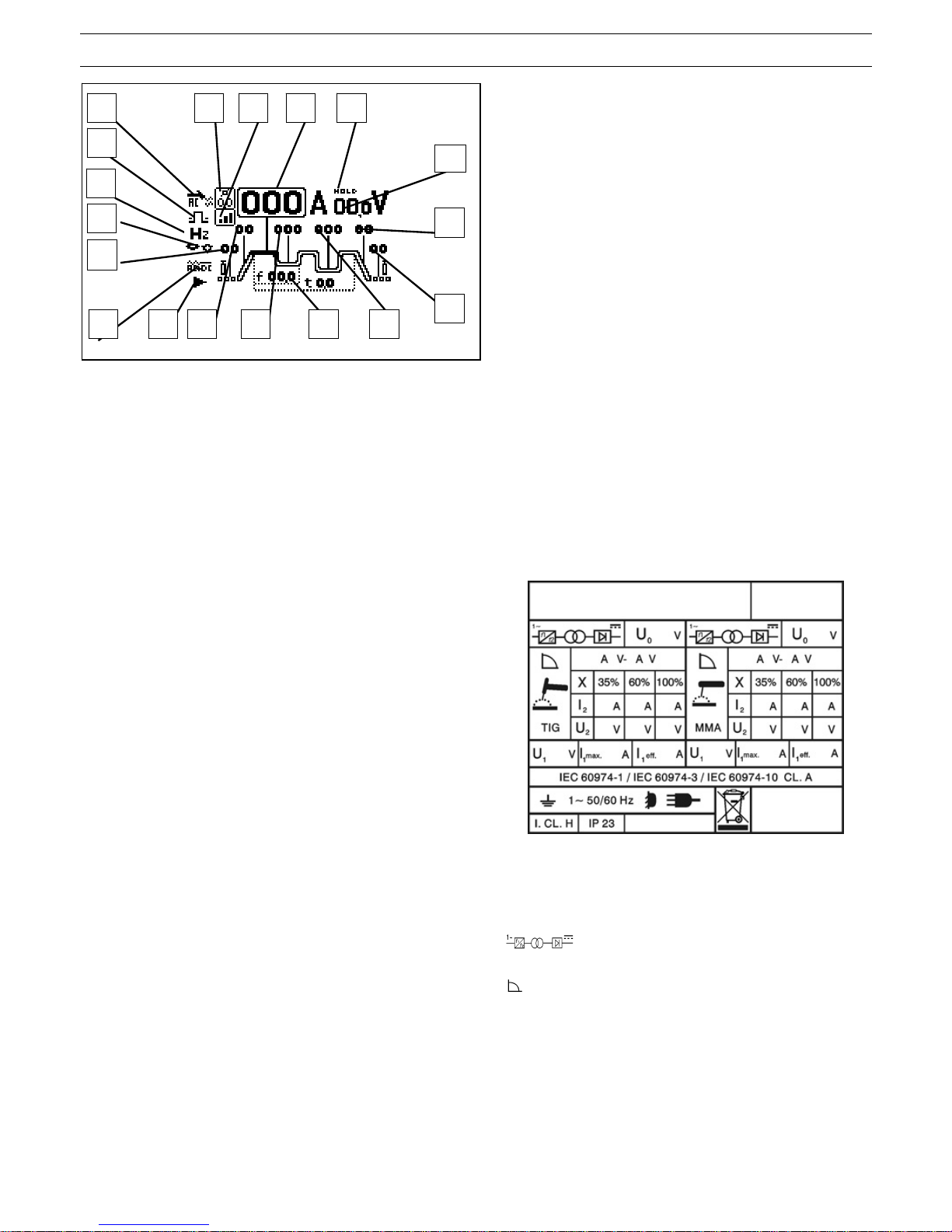
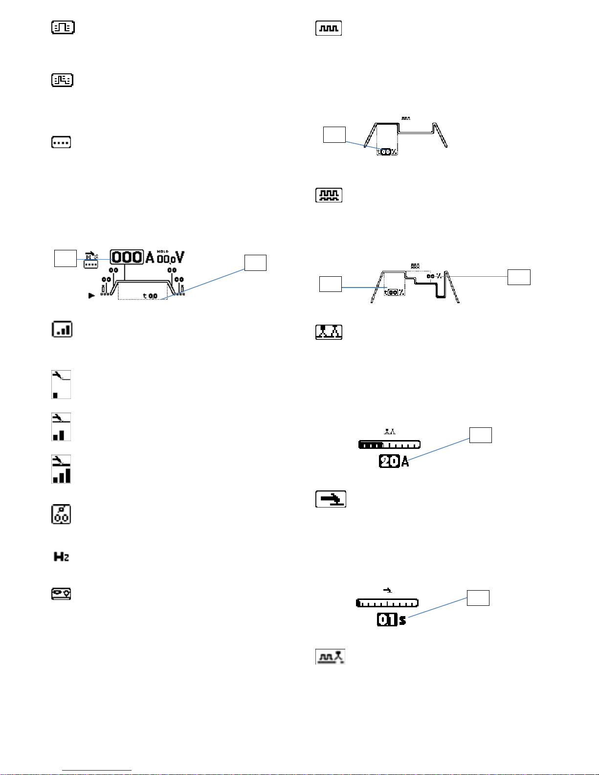
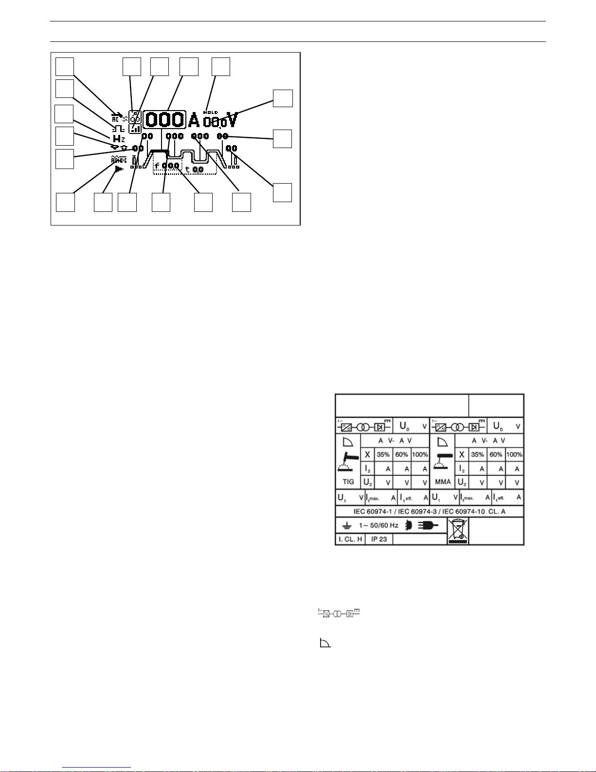
LEGENDA DISPLAY S2
A) METODO DI SALDATURA, s elezionandolo e premendo l’encoder si ha
accesso al menù di “metodo di saldatura”.
B) PROCEDIMENTO DI SALDATURA: selezionandolo e premendo
l’encoder si ha accesso al menù di “procedimento di saldatura”.
C) PRE-GAS: Regola Il tempo di uscita del gas prima dell'inizio della
saldatura (0,05-2,5 sec.), selezionandolo e premendo l’encoder si può
modificarne il tempo.
D) SOTTOMENU OPZIONI DI SALDATURA: selezionandolo e premendo
l’encoder si ha accesso al sottom enu delle opzioni di saldatura dove si
possono modificare i valori dipendentemente dalle opzioni scelte.
E) OPZIONI DI SALDATURA: selezionandolo e premendo l’encoder si ha
accesso al menù delle “opzioni di saldatura”, dove si può scegliere
l’opzione desiderata.
F) SLOPE-UP: è il tempo in cui la corrente, partendo dal minimo, raggiung e
il valore di corrente impostato. (0-10 sec.)
G) CORRENTE DI BASE IN OPZIONI ARCO PULSATO: selezionandolo e
premendo l’encoder si può modificarne il valore.
H) FREQUENZA DI PULSAZIONE: frequenza di pulsazione da 0,16 a 10 KHz, selezionandolo e premendo l’encoder si può modificarne il valore.
I) SECONDO LIVELLO DI CORRENTE IN MODO BI-LEVEL: selezionandolo e premendo l’encoder si può modificarne il valore.
L) POST GAS: Regola il tempo di uscita del gas al termine della saldatura. (0-30 sec.)
M) SLOPE DOWN: E' il tempo in cui la corrente raggiunge il minimo e lo spegnimento dell'arco. (0-10 sec.)
N) CORRENTE DI SALDATURA: selezionandolo e premendo l’encoder si può modificarne il valore.
O) HOLD: segnala che le grandezze visualizzate sul display corrente (fig.3, rif. N) e tensione (fig.3, rif. P) sono quelle utilizzate. Si attiva alla fine di ogni sa lda tura .
P) TENSIONE DI SALDATURA: visualizza la tensione d'arco in relazione al processo di saldatura in atto.
Q) TIPO DI ACCENSIONE DELL’ARCO: selezionandolo si ha accesso la sottomenu dove si può scegliere in che modo accendere l’arco
R) DIAMETRO DELL’ELETTRODO: selezionandolo e premendo l’encoder si può modificarne il valore.
S) FREQUENZA: selezionandolo e premendo l’encoder si può modificarne il valore.
T) BILANCIAMENTO DELL’ONDA: selezionandolo e premendo l’encoder si può modificarne il valore.
IMPORTANTE:
PRIMA DELL’INSTALLAZIONE, DELL’USO O DI QUALSIASI
MANUTENZIONE ALLA SALDATRICE LEGGERE IL
CONTENUTO DI QUESTO MANUALE E DEL MANUALE
“REGOLE DI SICUREZZA PER L’USO DELLE
APPARECCHIATURE” PONENDO PARTICOLARE
ATTENZIONE ALLE NORME DI SICUREZZA. CONTATTARE
IL VOSTRO DISTRIBUTORE SE NON AVETE COMPRESO
COMPLETAMENTE QUESTE ISTRUZIONI.
1. PREMESSA
Questo apparecchio deve essere utilizzato esclusivamente per
operazioni di saldatura. Non deve essere utilizzato per
scongelare tubi.
E’ inoltre indispensabile tenere nella massima considerazione
il manuale riguardante le regole di sicurezza.
I simboli posti in prossimità dei paragrafi ai quali si riferiscono,
evidenziano situazioni di massima attenzione, consigli pratici o
semplici informazioni.
Entrambi i manuali devono essere conservati con cura, in un
luogo noto ai vari interessati. Dovranno essere consultati ogni
qual volta vi siano dubbi, dovranno seguire tutta la vita
operativa della macchina e saranno impiegati per l’ordinazione
delle parti di ricambio.
2. DESCRIZIONI GENERALI
2.1. SPECIFICHE
Questa saldatrice è un generatore di corrente continua
costante realizzata con tecnologia INVERTER, progettata per
saldare gli elettrodi rivestiti (con esclusione del tipo cellulosico)
e con procedimento TIG con accensione a contatto e con alta
frequenza.
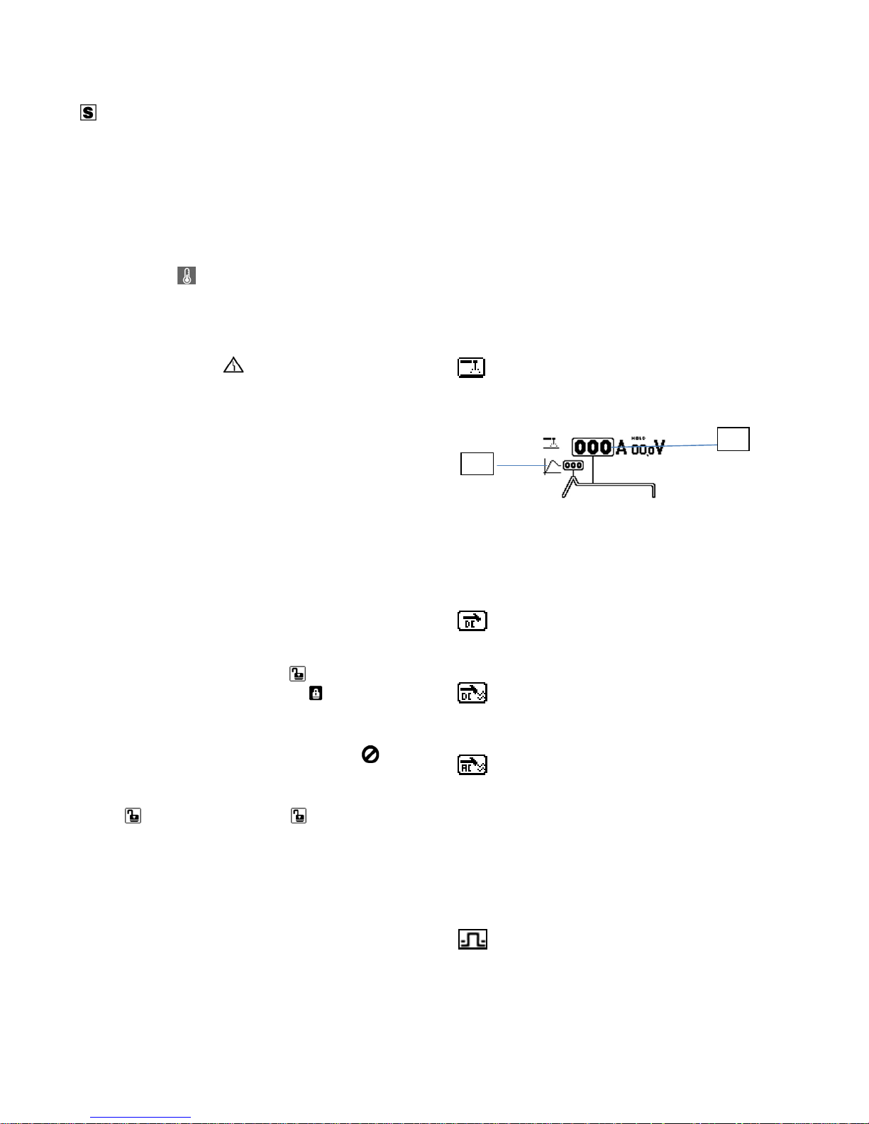
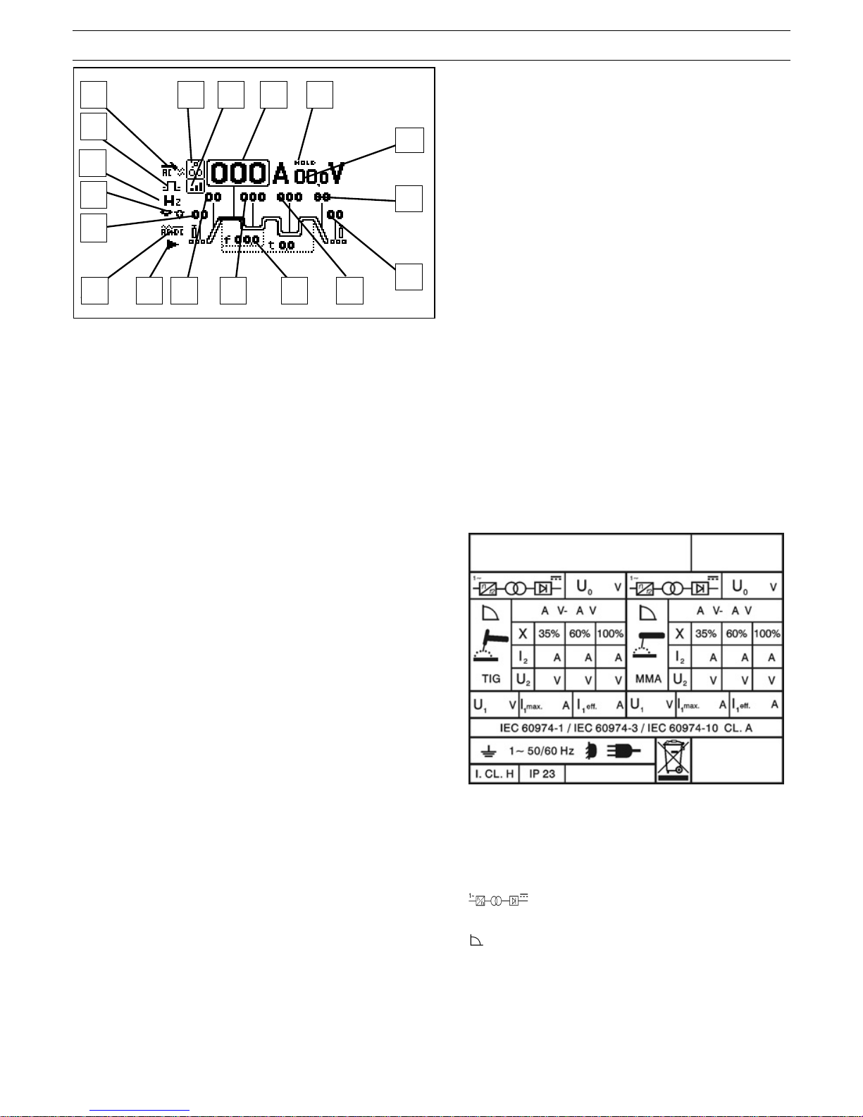
2.2. SPIEGAZIONE DEI DATI TECNICI RIPORTATI SULLA
TARGA DI MACCHINA
N° Numero di matricola da citare sempre per
qualsiasi richiesta relativa alla saldatrice.
IEC60974-1 La saldatrice é costruita secondo queste
IEC60974-10 norme internazionali.
Cl. A Apparecchiatura per uso industriale e
professionale.
Convertitore statico di frequenza monofase
trasformatore-raddrizzatore.
Caratteristica discendente.
MMA Adatto per saldatura con elettrodi rivestiti.
TIG Adatto per saldatura TIG.
U
0
Tensione a vuoto secondaria
X Fattore di servizio percentuale. % di 10 minuti in
cui la saldatrice può lavorare ad una determinata
corrente senza causare surriscaldamenti.
I2 Corrente di saldatura.
U
2
Tensione secondaria con corrente I2.
U
1
Tensione nominale di alimentazione.
1~ 50/60Hz Alimentazione monofase 50 oppure 60 Hz.
l1 max. E’ il massimo valore della corrente assorbita.
E
N
C
F G
M
L
D H I
Q
S
T
R
B
O A
4
l1 eff. E’ il massimo valore della corrente effettiva
assorbita considerando il fattore di servizio.
IP23 Grado di protezione della carcassa che omologa
l’apparecchio per lavorare all’esterno sotto la
pioggia.
Idoneità ad ambienti con rischio accresciuto.
NOTE: La saldatrice è inoltre idonea a lavorare in ambienti con
grado di inquinamento 3. (Vedi IEC 664).
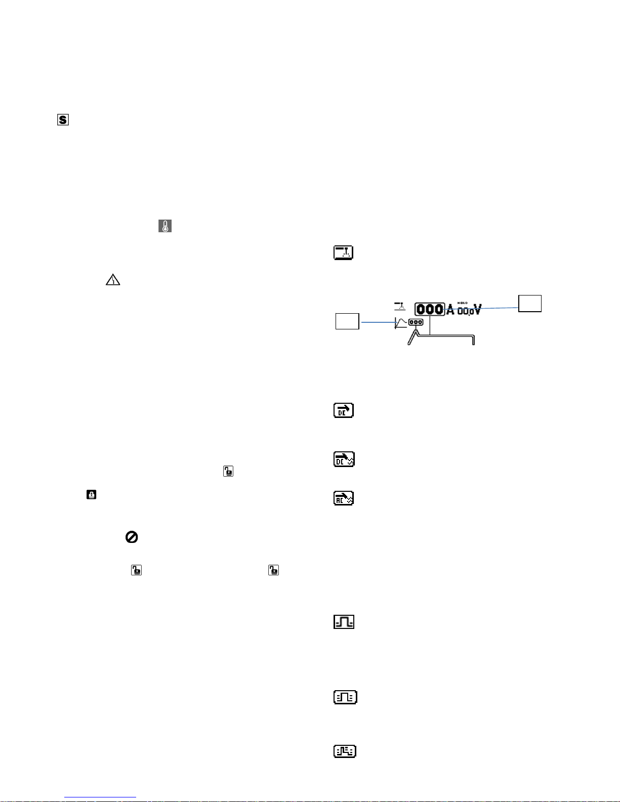
2.3. DESCRIZIONE DELLE PROTEZIONI
2.3.1. Protezione termica
Questo apparecchio è protetto da una sonda di temperatura la
quale, se si superano le temperature ammesse, impedisce il
funzionamento della macchina.
In queste condizioni il ventilatore continua a funzionare e verrà
visualizzata l’icona
sul display.
2.3.2. Protezione di blocco
Questa saldatrice è provvista di diverse protezioni che fermano
la macchina prima che subisca danni.
La segnalazione di fermo macchina è data dalla
visualizzazione del simbolo sul display.
L’accensione segnala:
1) Durante la fase di accensione, lo stato di alimentazione
della macchina.
2) Finita la fase di accensione, un’errata tensione di
alimentazione.
3) A macchina accesa, che la tensione è scesa sotto i 118V.
4) A macchina accesa, che la tensione di alimentazione
supera i 300V.
5) Se, durante la saldatura, la tensione supera i 300V. Per
ripristinare il funzionamento, verificare la tensione. Quindi
spegnere e riaccendere, dopo 5 secondi, l’interruttore. Se
l’inconveniente è stato risolto la saldatrice ricomincerà a
funzionare.
6) Se sul display compare la scritta E2 la macchina necessita
di un intervento tecnico.
2.3.3. Password
Quest’apparecchio è protetto contro l’uso da parte di personale
non autorizzato mediante la richiesta, all’accensione, di una
password.
Per attivare la funzione password, subito dopo l’accensione,
quando sul display viene visualizzato
premere l’encoder
S1, selezionare, ruotando l’encoder, l’icona
.
La password verrà richiesta alla successiva accensione, dove
si dovrà inserire ruotando l’encoder S1 fino al raggiungimento
della cifra corretta confermando premendo l’encoder S1; se il
codice è errato, il generatore si blocca visualizzando
e per
reinserire nuovamente la password è necessario spegnere e
riaccendere il generatore. Per rimuovere la funzione password,
una volta inserita, premere l’encoder quando sul display
appare
e selezionare l’icona , alla successiva
accensione la password non verrà richiesta. Il codice
password viene fornito insieme alla macchina e non si può
cambiare.
Si consiglia di custodirlo separatamente e in caso di
smarrimento, contattare il servizio assistenza.
Il generatore esce dalla fabbrica con la funzione disabilitata.
2.3.4. Funzioni opzioni bloccate
L’eventuale visualizzazione di un lucchetto su di un’opzione di
saldatura implica che è bloccata. Per attivarla, selezionare
l’icona desiderata nel menù di opzioni di saldatura (fig. 3 rif. E)
e inserire il codice di sblocco (optional).
2.3.5. Motogeneratori
Monofase: debbono avere un dispositivo di regolazione
elettronico della tensione, una potenza uguale o superiore a
4,5 kVA per art. 156 e art. 166, a 5 kVA per art. 158 ed a 6,5
kVA per art. 168 e non debbono erogare una tensione
superiore a 260V.
3. INSTALLAZIONE
Controllare che la tensione di alimentazione corrisponda alla
tensione indicata sulla targa dei dati tecnici della saldatrice.
La portata dell'interruttore magnetotermico o dei fusibili, in
serie alla alimentazione, deve essere uguale alla corrente I
1
assorbita dalla macchina.
ATTENZIONE!: Le prolunghe fino a 30m devono essere
almeno di sezione 2,5 mm
2
.
3.1. MESSA IN OPERA
L'installazione della macchina deve essere fatta da personale
esperto. Tutti i collegamenti debbono essere eseguiti in
conformità alle norme vigenti e nel pieno rispetto della legge
antinfortunistica (norma CEI 26-10- CENELEC HD 427).
3.2. TIPO DI SALDATURA
Per selezionare il metodo di saldatura ruotare l’encoder S1 fino
a selezionare l’icona (fig. 3 rif. A), premere l’encoder per
accedere al menù per la selezione del metodo di saldatura.
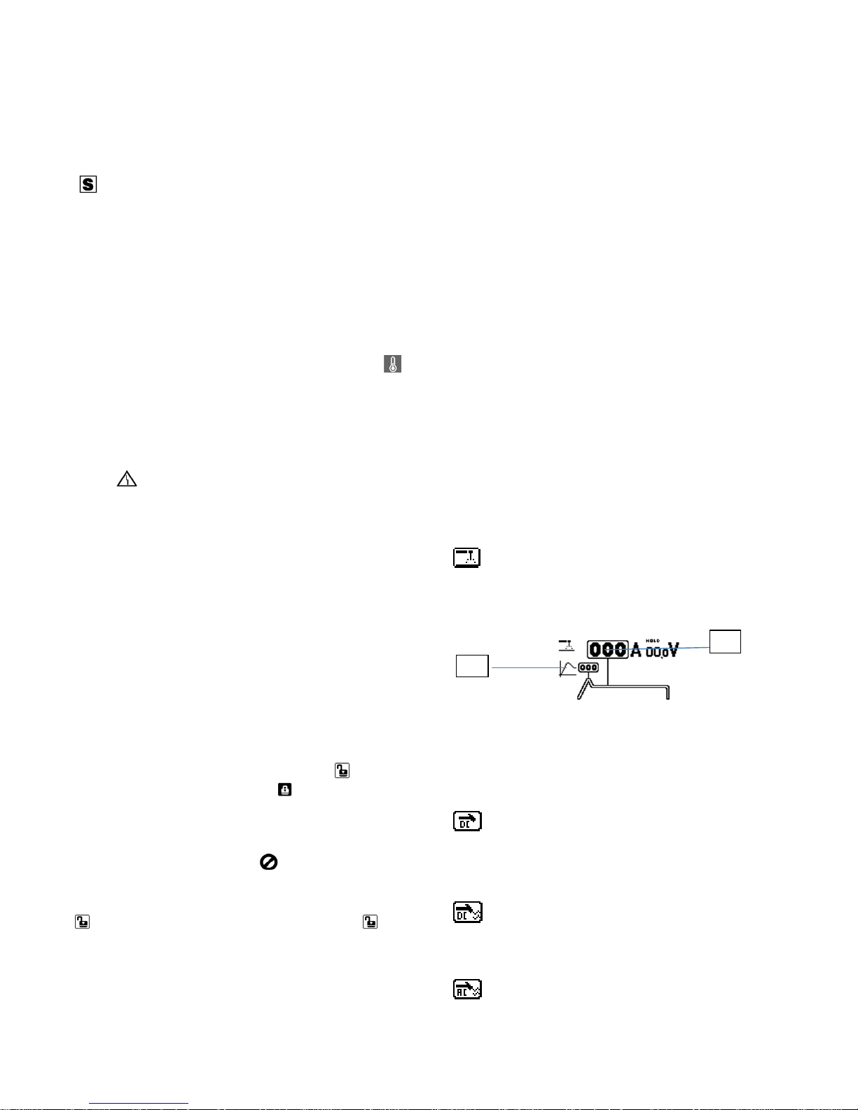
SALDATURA AD ELETTRODO MMA
Questa macchina può fondere tutti i tipi di elettrodi rivestiti
escluso il tipo cellulosico. Con il metodo MMA si possono
modificare i seguenti parametri
Fig.4
- OPZIONE DI HOT START (fig. 4, rif.1)
Regola una sovracorrente che può essere inserita per
favorire l’accensione dell’arco.
- CORRENTE DI SALDATURA(fig. 4 rif. 2)
Ruotando l’encoder S1 si può impostare la corrente
corretta di saldatura.
SALDATURA A TIG DC (ACCENSIONE PER
CONTATTO). Per accendere l'arco premere il pulsante torcia e
toccare con l'elettrodo di tungsteno il pezzo da saldare e
rialzarlo. Il movimento deve essere deciso e rapido.
SALDATURA A TIG DC (ACCENSIONE IN ALTA
FREQUENZA). Per accendere l'arco premere il pulsante
torcia, una scintilla pilota di alta tensione/frequenza accenderà
l'arco.
S ALDATURA A TIG AC-DC (ACCENSIONE IN ALTA
FREQUENZA): solo artt.166-168. Per accendere l'arco
premere il pulsante torcia, una scintilla pilota di alta
tensione/frequenza accenderà l'arco.
3.3. SELEZIONARE IL MODO DI SALDATURA
Ruotare l’encoder S1 fino a selezionare il procedimento di
saldatura (fig. 3 rif. B) e premere, scegliere poi l’icona
desiderata. In tutti i modi, selezionare preventivamente il
valore di pre gas(fig. 3 rif. C) e post gas (fig. 3 rif. L).
SALDATURA A TIG 2 TEMPI (MANUALE)
Premendo il pulsante della torcia la corrente inizia ad
aumentare ed impiega un tempo corrispondente allo "slope up"
(fig. 3 rif. F) preventivamente regolato, per raggiungere il
valore. Quando si lascia il pulsante la corrente inizia a
diminuire ed impiega un tempo corrispondente allo "slope
down" (fig. 3 rif. M) preventivamente regolato, per ritornare a
zero.
1
2
5
SALDATURA A TIG 4 TEMPI (AUTOMATICO). Questo
programma differisce dal precedente perché sia l'accensione
che lo spegnimento vengono comandati premendo e
rilasciando il pulsante della torcia TIG.
SALDATURA A TIG 4 TEMPI CON DUE LIVELLI DI
CORRENTE(AUTOMATICO BILEVEL). Prima di accendere
l'arco impostare i due livelli di corrente, di saldatura (fig. 3 rif.
N)e (fig. 3 rif. I),di “slope up” e “slope down” ruotando l’
encoder e premendo sul valore per poi impostarlo.
PUNTATURA. Scegliere la corrente di saldatura(fig. 5 rif.
A) e il tempo di puntatura (fig. 5 rif. B) tramite l’encoder S1,
ruotandolo fino al parametro desiderato e premendolo per
impostarne i valori.
In questo modo di saldatura l'operatore preme il pulsante della
torcia, si accende l'arco e, dopo il tempo di puntatura regolato,
l'arco si spegne automaticamente. Per eseguire il punto
successivo è necessario rilasciare il pulsante torcia e poi
ripremerlo.
Fig.5
TIPO DI ACCENSIONE DELL’ARCO: solo per
artt.166-168. Selezionando questa icona tramite l’encoder S1
si accede al menù di accensione dove si può decidere fra le
seguenti opzioni:
INIZIO SALDATURA DAL BORDO CON MATERIALE
SOTTILE
INIZIO SALDATURA DAL CENTRO CON MATERIALE
SOTTILE
INIZIO SALDATURA DAL CENTRO CON MATERIALE
SPESSO
DIAMETRO DELL’ELETTRODO: solo per artt.166-168.
Regola la partenza in funzione del diametro dell’elettrodo.
FREQUENZA AC: solo per artt.166-168. Regola la
frequenza della corrente alternata da 10 a 150Hz.
BILANCIAMENTO DELL’ONDA: solo per artt.166-168.
Regola la pulizia da –8 a 0 o la penetrazione da 0 a 8.
3.4. OPZIONI DI SALDATURA (DISPONIBILI SOLO PER
SALDATURA A TIG )
Per selezionare le opzioni di saldatura occorre prima di tutto
aver impostato precedentemente la macchina sul metodo di
saldatura a TIG, normale o alta frequenza, dopo di che,
indifferentemente dal procedimento, selezionare l’icona delle
opzioni (fig. 3 rif. E) ruotando e premendo l’encoder,
selezionando l’opzione desiderata fra le seguenti:
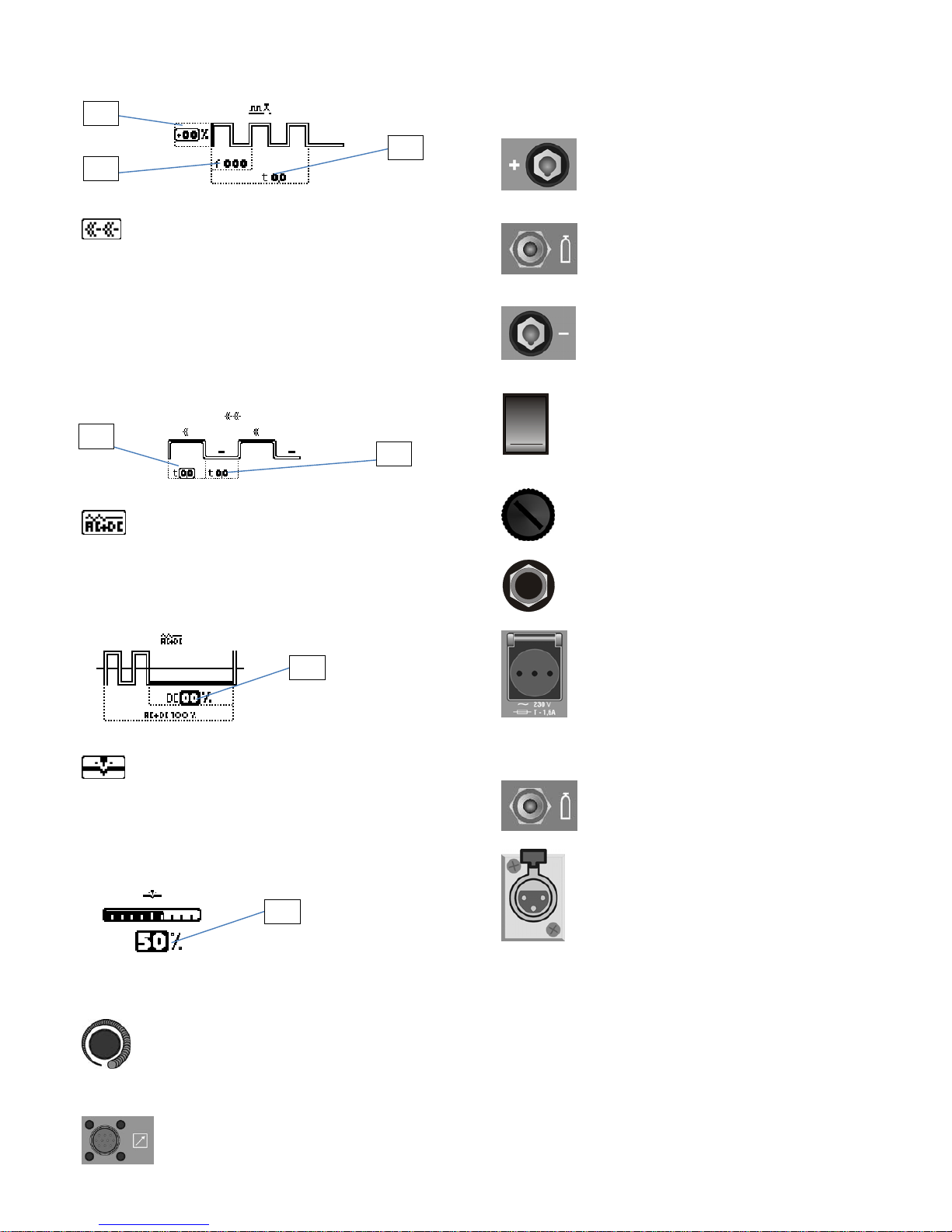
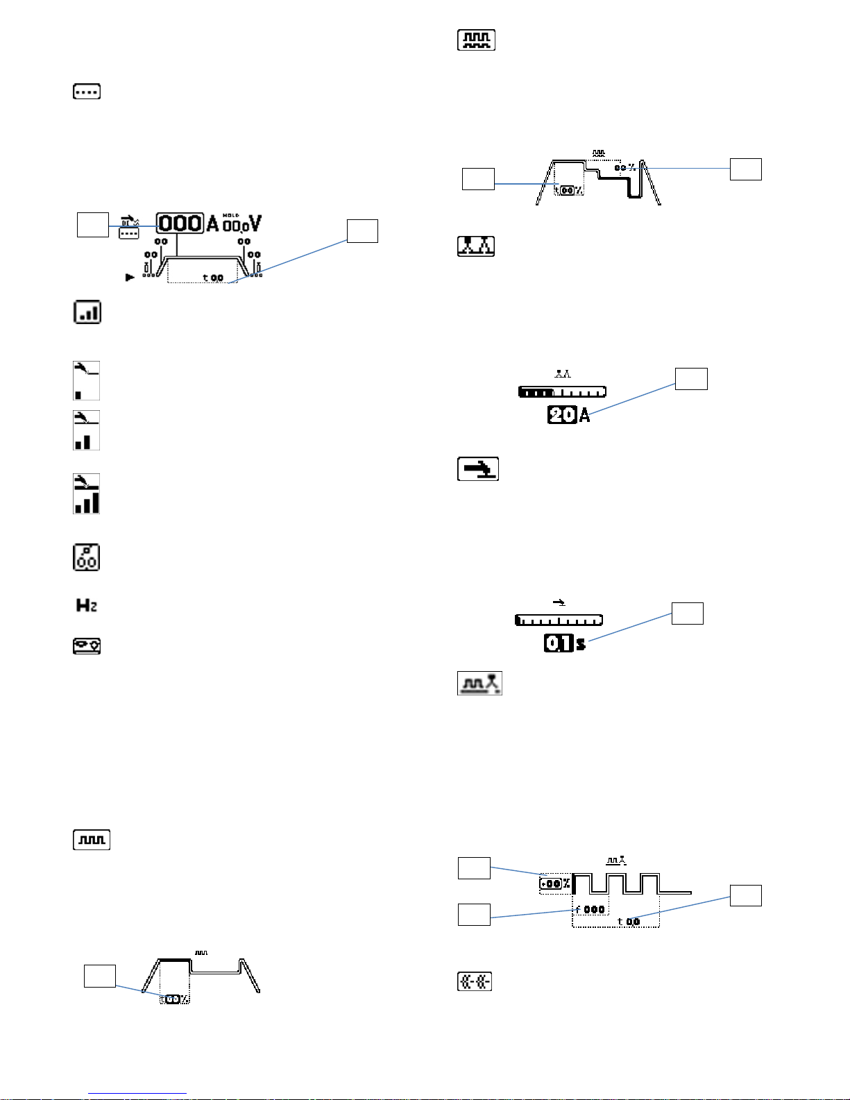
OPZIONE SALDATURA PULSATA. Impostare la
corrente di saldatura principale (fig. 3 rif. N), la corrente base
(fig. 3 rif. G), la frequenza della pulsazione (fig. 3 rif. H),
selezionare, infine, tramite l’encoder S1 il sottomenù di
opzione (fig. 3 rif. D) e regolare la durata della corrente di
principale espressa in percentuale del periodo (fig. 6 rif. A) tra
20% e 80%.
Fig.6
OPZIONE SALDATURA E-TWO PULSE
(OPTIONAL). Impostare i parametri di saldatura come
nell’opzione pulsata, selezionare, infine, tramite l’encoder S1 il
sottomenù di opzione (fig. 3 rif. D) e regolare la durata della
corrente di picco espressa in percentuale del periodo (fig. 7 rif.
A) e il rapporto in percentuale di riduzione della seconda
pulsazione rispetto alla prima (fig. 7 rif. B).
Fig.7
OPZIONE DI SALDATURA E-ARC (OPTIONAL)
SOLO TIG DC. Arco di saldatura intelligente che permette di
controllare la corrente e il cordone di saldatura in DC,
semplicemente muovendo la torcia. Prima di iniziare la
procedura di saldatura impostare la corrente di saldatura (fig. 3
rif. N) e selezionare, infine, tramite l’encoder S1 il sottomenù di
opzione (fig. 3 rif. D) e regolare la variazione di corrente
gestibile alzando o abbassando la torcia durante la saldatura.
Parametro regolabile da 1 a 50 A (fig. 8 rif. A).
fig.8
OPZIONE DI SALDATURA E-SPOT (OPTIONAL)
SOLO TIG DC. Speciale puntatura utilizzabile solo nel metodo
di saldatura DC a contatto che consente di ridurre
drasticamente l'apporto termico ed ottenere facilmente punti di
saldatura bianchi e lucidi su lamiere difficili da puntare come
l'acciaio inox impostare la corrente di saldatura (fig. 3 rif. N) e
selezionare, infine, tramite l’encoder S1 il sottomenù di
opzione(fig. 3 rif. D) e regolare il tempo di puntatura .
Parametro regolabile da 0.01 a 9.90 sec (fig. 9 rif. A)
Fig.9
OPZIONE DI SALDATURA E-START (OPTIONAL)
SOLO TIG DC. Start pulsato utilizzabile solo nel metodo di
saldatura in DC con innesco ad alta frequenza, utilissimo per
ottimizzare la puntatura delle lamiere nella fase iniziale della
saldatura. Impostare la corrente di saldatura (fig. 3 rif. N),
selezionare, infine, tramite l’encoder S1 il sottomenù di
opzione (fig. 3 rif. D) e impostare la percentuale della seconda
corrente di saldatura pulsata rispetto alla prima (fig. 10 rif. A)
A
A
A
B
A
A
B
6
dal -50% a + 99%, la frequenza di saldatura (fig. 10 rif. B),da
50 a 200Hz, e il tempo di puntatura (fig. 10 rif. C) da 0,1 a 9,9
sec.
Fig.10
OPZIONE DI SALDATURA E- MULTIPOINT
(OPTIONAL) SOLO TIG DC
Nuovo sistema di saldatura pulsata utilizzabile solo nel metodo
di saldatura in DC con innesco ad alta frequenza che permette
di alternare rapidamente il tempo di lavoro e il tempo di pausa
a corrente zero, per consentire al pezzo un adeguato
raffreddamento ed una conseguente forte riduzione di
alterazione termica.Impostare il valore della corrente di
saldatura (fig. 3 rif. N), selezionare, infine, tramite l’encoder S1
il sottomenù di opzione(fig. 3 rif. D) e impostare il tempo di
saldatura da 0,05 a 9,90 sec (fig. 11 rif. A), ed il tempo di
pausa da 0,1 a 9,9 sec (fig. 11 rif. B).
Fig.11
OPZIONE DI SALDATURA E-MIX (OPTIONAL)
SOLO TIG AC
scegliendo questa opzione è possibile saldare per una parte di
periodo in alternata e una parte di periodo in continua.
Selezionando il sottomenu di opzioni di saldatura (fig. 3 rif. D)
è possibile impostare la durata della corrente continua in
percentuale del periodo (fig. 12 rif. A).
Fig.12
OPZIONE SALDATURA E-FUSION (OPTIONAL)
SOLO TIG AC
scegliendo questa opzione di saldatura è possibile scegliere
quanto a fondo penetrare dentro il materiale durante la
saldatura. Selezionando il sottomenu di opzioni di saldatura
(fig. 3 rif. D) è possibile impostare la percentuale che indica la
differenza tra semionda positiva e negativa, aumentando la
percentuale aumenta la semionda positiva (fig. 13 rif. A).
Fig.13
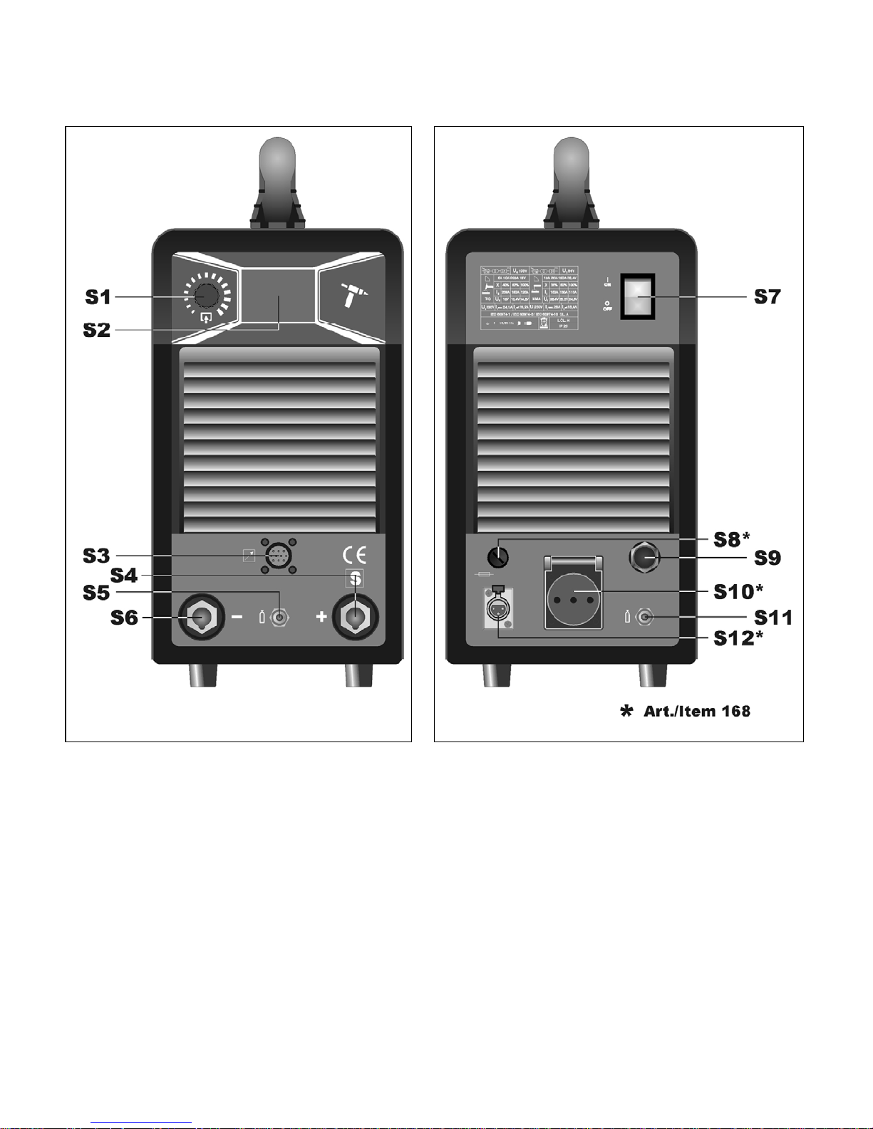
3.5. DESCRIZIONE DELL’APPARECCHIO (fig. 1 e 2).
S1 - Encoder.
Ruotare per scorrere le icone selezionabili.
Premere per selezionare l’icona evidenziata.
S3 –CONNETTORE 10 POLI.
A questo connettore vanno collegati i
seguenti comandi remoti:
a) pedale
b) torcia con pulsante di start
c) torcia con potenziometro
d) torcia con up/down
e) comando a distanza ecc…
S4
Morsetto di uscita positivo (+)
S5 –Raccordo ¼ gas.
Vi si connette il tubo gas della torcia di saldatura TIG.
S6
Morsetto di uscita negativo (-)
S7 –Interruttore.
Accende e spegne la macchina
S8 – Portafusibile (Solo per art.168)
S9 - Cavo di alimentazione.
S10 – Presa (Solo per art.168)
A cui collegare il gruppo di raffreddamento.
Attenzione: Potenza max: 360VA - Ampere: 1,6.
Non collegare utensili quali smerigliatrici o similari.
S11 - Raccordo ingresso gas.
S12 – Connettore (Solo per art.168)
Connettore a tre poli a cui va collegato il cavetto
del pressostato del gruppo di raffreddamento. In assenza del
gruppo di raffreddamento, collegare il connettore metallico a 3
poli in dotazione.
3.6. NOTE GENERALI
Prima dell'uso di questa saldatrice leggere attentamente le
norme CEI 26/9 - CENELEC HD 407 e CEI 26.11 - CENELEC
HD 433 inoltre verificare l'integrità dell'isolamento dei cavi,
delle pinze porta elettrodi, delle prese e delle spine e che la
sezione e la lunghezza dei cavi di saldatura siano compatibili
con la corrente utilizzata.
A
B
A
C
B
A
A

7
3.7. SALDATURA DI ELETTRODI RIVESTITI (MMA)
- Questa saldatrice è idonea alla saldatura di tutti i tipi di
elettrodi ad eccezione del tipo cellulosico (AWS 6010).
- Assicurarsi che l'interruttore S7 sia in posizione 0, quindi
collegare i cavi di saldatura rispettando la polarità richiesta
dal costruttore di elettrodi che andrete ad utilizzare e il
morsetto del cavo di massa al pezzo nel punto più vicino
possibile alla saldatura assicurandosi che vi sia un buon
contatto elettrico.
- Non toccare contemporaneamente la torcia o la pinza
porta elettrodo ed il morsetto di massa.
- Accendere la macchina mediante l'interruttore S7.
- Selezionare il procedimento MMA,
, come descritto al
paragrafo 3.2.
- Con procedimento MMA la ventola di raffreddamento è
sempre attiva.
- Regolare la corrente in base al diametro dell'elettrodo, alla
posizione di saldatura e al tipo di giunto da eseguire.
- Terminata la saldatura spegnere sempre l'apparecchio
e togliere l'elettrodo dalla pinza porta elettrodo.
3.8. SALDATURA TIG
Questa saldatrice è idonea a saldare con procedimento TIG
l'acciaio inossidabile, il ferro, il rame.
Collegare il connettore del cavo di massa al polo positivo (+)
della saldatrice e il morsetto al pezzo nel punto più vicino
possibile alla saldatura assicurandosi che vi sia un buon
contatto elettrico.
Collegare il connettore di potenza della torcia TIG al polo
negativo (-) della saldatrice.
Collegare il connettore di comando della torcia al connettore
S3 della saldatrice.
Collegare il raccordo del tubo gas della torcia al raccordo S5
della macchina ed il tubo gas proveniente dal riduttore di
pressione della bombola al raccordo gas S11.
Accendere la macchina.
Non toccare parti sotto tensione e i morsetti di uscita quando
l'apparecchio è alimentato.
Alla prima accensione della macchina selezionare il modo e i
parametri di saldatura come indicato al paragrafo 3.2.
Con procedimento TIG la ventola di raffreddamento si attiva,
dopo 5 secondi si ferma per poi ripartire in fase di saldatura
fino al raffreddamento della macchina.
Il flusso di gas inerte deve essere regolato ad un valore (in litri
al minuto) di circa 6 volte il diametro dell'elettrodo.
Se si usano accessori tipo il gas-lens la portata di gas può
essere ridotta a circa 3 volte il diametro dell'elettrodo. Il
diametro dell'ugello ceramico deve avere una dimensione da 4
a 6 volte il diametro dell'elettrodo.
Normalmente il gas più usato è l'ARGON perché ha un costo
minore rispetto agli altri gas inerti, ma possono essere usate
anche miscele di ARGON con un massimo del 2%
IDROGENO per la saldatura dell'acciaio inossidabile e ELIO o
miscele di ARGON-ELIO per la saldatura del rame. Queste
miscele aumentano il calore dell'arco in saldatura ma sono
molto più costose.
Se si usa gas ELIO aumentare litri al minuto fino a 10 volte il
diametro dell'elettrodo (Es. diametro 1,6 x10= 16 l/min. di Elio).
Usare vetri di protezione D.I.N. 10 fino a 75A e D.I.N. 11 da
75A in poi.
3.9. MEMORIZZAZIONE DI UN PROGRAMMA
E POSSIBILE MEMORIZZARE SOLO DOPO AVER
SALDATO, AD OGNI ACCENSIONE LA MACCHINA
PRESENTA SEMPRE L’ULTIMA CONDIZIONE UTILIZZATA
IN SALDATURA.
3.9.1. Memorizzare i dati
Per memorizzare un programma occorre prima di tutto
impostare i parametri relativi al processo, metodo e opzioni di
saldatura ed eseguire una saldatura anche breve. Tramite
l’encoder S1 selezionare l’icona (fig. 3 rif. A) e accedere al
menù. ruotare l’encoder fino a selezionare l’icona scegliere
la riga di salvataggio ruotando l’encoder S1 e selezionarla
premendolo. Selezionare l’icona ed inserire il nome da
dare al programma, selezionando numeri o lettere tramite
l’encoder S1, confermare selezionando l’icona
.
3.9.2. Cancellare i dati
Tramite l’encoder S1 selezionare l’icona (fig. 3 rif. A) e
accedere al menù, ruotarlo fino a selezionare l’icona
scegliere la riga da cancellare tramite l’encoder S1 e
selezionarla premendolo. Una volta selezionato il programma
da cancellare, ruotare l’encoder fino a selezionare l’icona
.
3.9.3. Aggiornare
È possibile modificare i programmi precedentemente salvati,
memorizzandoli sulla stessa posizione o su una nuova.
3.10. GRUPPO DI RAFFREDDAMENTO (optional solo per
art. 168)
Se si utilizza una torcia raffreddata ad acqua utilizzare il
gruppo di raffreddamento.
Collegare il cavo di alimentazione del gruppo di
raffreddamento alla presa S10 del generatore ed inserire poi il
connettore tre poli metallico al connettore S12 del generatore.
in caso di assenza del gruppo di raffreddamento collegare il
connettore a corredo per simulare la presenza del gruppo. In
assenza di tale connettore o con liquido refrigerante
insufficiente il generatore rimane in blocco e verrà visualizzata
l’ icona
sul display.
Attenzione! Se selezionata la saldatura in elettrodo, il
raffreddamento non è acceso e non è selezionabile.
4. COMANDI A DISTANZA
Per la regolazione della corrente di saldatura a questa
saldatrice possono essere connessi i seguenti comandi a
distanza:
Art. 570008 Comando a pedale (usato in saldatura TIG).
Art. 535805 Torcia TIG UP/DOWN.
Art. 530330 +Art. 570006 (usato in saldatura MMA).
Art. 363307 Connessione per collegare la torcia e il comando a
pedale contemporaneamente. Con questo accessorio l’Art.
570008 può essere utilizzato in qualsiasi modo di saldatura
TIG.
I comandi che includono un potenziometro regolano la
corrente di saldatura dal minimo fino alla massima
corrente impostata con la encoder S1.
I comandi con logica UP/DOWN regolano dal minimo al
massimo la corrente di saldatura.
8
3
INSTRUCTION MANUAL FOR ARC WELDING MACHINES
DISPLAY S2 LEGEND
A) WELDING METHOD: Select this and press the encoder to access the
"welding method" menu.
B) WELDING PROCEDURE: Select this and press the encoder to access the
"welding procedure" menu.
C) PRE-GAS: This is the time for exit of the gas before welding (0.05-2.5
sec). Select this and press the encoder to modify the time.
D) WELDING OPTIONS SUB-MENU: Select this and press the encoder to
access the welding options sub-menu, and sel ect an option to modify its
values.
E) WELDING OPTIONS: Select this and press the encoder to access the
"welding options" menu, and select the required option.
F) SLOPE-UP: This is the time it takes for the current to reac h the set value
from minimum. (0-10 sec.)
G) BASE CURRENT FOR PULSED ARC WELDING: Select this and press
the encoder to modify its value.
H) PULSE FREQUENCY: The pulse frequency is betwe en 0.16 and 10 K Hz.
Select this and press the encoder to modify its value.
I) CURRENT LEVEL TWO IN BI-LEVEL MODE: Select this and press the encoder to modify its value.
L) POST GAS: This is the time for exit of the gas after welding. (0-30 sec.)
M) SLOPE DOWN: This is the time during which the current decreases to minimum and the arc turns off. (0-10 sec.)
N) WELDING CURRENT: Select this and press the encoder to modify its value.
O) HOLD: Indicates that the current (fig. 3, ref. N) and voltage (fig. 3, ref. P) values on the display are t hose in use. This is activated at the e nd of each welding
process.
P) WELDING VOLTAGE: This shows the arc voltage in relation to the welding process carried out.
Q) TYPE OF ARC STRIKE: Select this to access the sub-menu and select and strike the arc.
R) DIAMETER OF ELECTRODE: Select this and press the encoder to modify its value.
S) FREQUENCY: Select this and press the encoder to modify its value.
T) WAVE BALANCE CONTROL: Select this and press the encoder to modify its value.
IMPORTANT
READ THIS MANUAL AND THE “SAFETY RULES” MANUAL
CAREFULLY BEFORE INSTALLING, USING, OR SERVICING
THE WELDING MACHINE, PAYING SPECIAL ATTENTION TO
SAFETY RULES.
CONTACT YOUR DISTRIBUTOR IF YOU DO NOT FULLY
UNDERSTAND THESE INSTRUCTIONS.
1. PRECAUTIONS
This machine must be used for welding only. It must not be used
to defrost pipes.
It is also essential to pay special attention to the "SAFETY
RULES" Manual. The symbols next to certain paragraphs
indicate points requiring extra attention, practical advice or
simple information.
This MANUAL and the "SAFETY RULES" MANUAL must be
stored carefully in a place familiar to everyone involved in using
the machine. They must be consulted whenever doubts arise
and be kept for the entire lifespan of the machine; they will also
be used for ordering replacement parts.
2. GENERAL DESCRIPTIONS
2.1. SPECIFICATIONS
This welding machine is a constant current power source built
using INVERTER technology, designed to weld covered
electrodes (not including cellulosic) and for TIG procedures, with
contact starting and high frequency.
2.2. EXPLANATION OF THE TECHNICAL
SPECIFICATIONS LISTED ON THE MACHINE PLATE.
N°
Serial number, which must be indicated on any
type of request regarding the welding machine.
IEC60974-1 This welding machine is manufactured
according
IEC60974-10 to this international standards
Cl. A Machine for professional and industrial use
Single-phase static transformer-rectifier
frequency converter.
Drooping-characteristic.
MMA Suitable for welding with covered electrodes.
TIG Suitable for TIG welding.
U
0
Secondary open-circuit voltage
X Duty cycle percentage. % of 10 minutes during
which the welding machine may run at a
certain current without overheating.
I2 Welding current.
E
N
C
F G
M
L
D H I
Q
S
T
R
B
O A
9
U2 Secondary voltage with current I2.
U
1
Rated supply voltage.
1- 50/60Hz 0- or 60-Hz single-phase power supply.
I1 max. This is the maximum value of the absorbed
current.
I1 eff. This is the maximum value of the actual current
absorbed, considering the duty cycle.
IP23 Protection grade of the housing, approving the
equipment as suitable for use outdoors in the rain.
Suitable for hazardous environments.
NOTES: the welding machine has also been designed for use in
environments with a pollution rating of 3. (See IEC 664).
2.3. DESCRIPTION OF PROTECTIVE DEVICES
2.3.1. Thermal protection
This machine is protected by a temperature probe, which
prevents the machine from operating if the allowable
temperatures are exceeded. Under these conditions the fan
keeps running and the icon
appears on the display.
2.3.2. Block protections
This welding machine is equipped with various safety devices
that stop the machine before it can suffer damage.
The symbol
appears on the display when the machine
stops. When this occurs, it signals:
1) During the start-up phase, the power status of the machine.
2) After the start-up phase, incorrect supply voltage.
3) With the machine running, that the voltage has fallen below
118V.
4) With the machine running, that the supply voltage is above
300V.
5) During welding, that the voltage exceeds 300V. To restore
operation, check the voltage. Then shut off the switch, wait
5 seconds, and switch it on again. If the problem has been
corrected, the weIding machine will begin operating again.
6) If the message E2 appears on the display, the machine
requires technical intervention.
2.3.3. Password
This equipment is protected against the use on behalf of
unauthorised personnel through the request, on ignition, of a
password.
To activate the password function: when
appears on the
display upon start-up, immediately press encoder S1, and select
the icon
by turning the encoder.
The user is prompted to log in when the system is next started
up. Turn encoder S1 to enter the correct password and then
press encoder S1 to confirm it. If the code is incorrect, the power
source locks and
appears on the display. To re-enter the
password, turn the power source off and then on again. To
remove the password function when this is enabled, press the
encoder and when
appears on the display, select . The
log-in function will not appear upon next start-up.
The password code is supplied together with the machine and
cannot be changed.
It is recommended to keep it separate and in case of loss,
contact the after-sales assistance.
The power source leaves the factory with the function disabled.
2.3.4. Disabled options
A padlock symbol next to a welding option indicates that it is
disabled. To enable it, select the required icon in the welding
options menu (fig. 3 ref. E) and enter the release code (optional).
2.3.5. Motor-driven generators
Single-phase: they must have an electronic regulator of the
tension, a power equal to or greater than 4,5 kVA for item 156
and item 166, than 5 kVA for item 158 and 6,5 kVA for tem 168,
and must not deliver a voltage greater than 260V.
3. INSTALLATION
Make sure that the supply voltage matches the voltage
indicated on the specification plate of the welding machine.
The capacity of the overload cut-out switch or fuses installed
in series with the power supply must be equivalent to the
absorbed current I1 of the machine.
WARNING! Extension cords of up to 30m must have a crosssection of at least 2.5 mm2.
3.1. START-UP
Only skilled personnel should install the machine. All
connections must be carried out according to current
regulations, and in full observance of safety laws (regulation
CEI 26-10 -CENELEC HD 427).
3.2. TYPE OF WELDING
To select the welding method, turn encoder S1 to select the
icon (fig. 3 ref. A) and press the encoder to access the menu
for selecting the welding method.
MMA ELECTRODE WELDING
This machine can smelt all types of coated electrodes apart
from the cellulosic type. The following parameters can be
modified for the MMA method.
Fig.4
- HOT START OPTION (fig. 4, ref. 1)
This is overcurrent that can be enabled to ignite the arc.
- WELDING CURRENT (fig. 4 ref. 2)
Turn encoder S1 to set the correct welding current.
DC TIG WELDING (CONTACT IGNITION). To ignite
the arc, press the torch button and touch the piece to be
welded with the tungsten electrode and lift it. The movement
should be firm and quick.
DC TIG WELDING (IGNITION AT HIGH
FREQUENCY). To ignite the arc, press the torch button. A
pilot spark at high voltage/frequency ignites the arc.
AC-DC TIG WELDING (IGNITION AT HIGH
FREQUENCY): only items 166-168. To ignite the arc, press
the torch button. A pilot spark at high voltage/frequency
ignites the arc.
3.3. SELECTING THE WELDING METHOD
Turn encoder S1 to select the welding procedure (fig. 3 ref.
B) and press it. Select the required icon. For each method,
first select the pre-gas value (fig. 3 ref. C) and post-gas value
(fig. 3 ref. L).
2-TIME TIG WELDING (MANUAL)
Press the torch button. The current gradually increases,
during the previously set "slope up" time (fig. 3 ref. F), up to
the required value. When the button is released, the current
decreases, during the previously set "slope down" time (fig. 3
ref. M), down to the zero point.
4-TIME TIG WELDING (AUTOMATIC) This program
differs from the previous one in that ignition and extinction
are controlled by pressing and releasing the button on the
TIG torch.
4-TIME TIG WELDING WITH TWO CURRENT
LEVELS (AUTOMATIC BI-LEVEL) Before igniting the arc,
1
2
10
set the two current levels for welding, "slope up" and "slope
down" (fig. 3 ref. N and fig. 3 ref. I), by turning the encoder and
pressing the value to set it.
SPOT WELDING Select the welding current (fig. 5 ref. A)
and the spot welding time (fig. 5 ref. B), turning encoder S1 to
select the required parameter and pressing it to set the values.
For this welding method, press the button on the torch and the
arc ignites; the arc is extinguished automatically at the end of the
set spot welding time. To do the next spot, release the torch
button and then press it again.
Fig.5
TYPE OF ARC IGNITION: only for items 166-168. Using
encoder S1, select this icon to access the ignition menu and
choose between the following options:
START WELDING FROM EDGE WITH THIN MATERIAL
START WELDING FROM CENTRE WITH THIN
MATERIAL
START WELDING FROM CENTRE WITH THICK
MATERIAL
DIAMETER OF ELECTRODE: only for items 166-168.
This is to set ignition in relation to the diameter of the electrode.
AC FREQUENCY: only for items 166-168. This is to set
the frequency of the alternating current between 10 and 150Hz.
WAVE BALANCE CONTROL: only for items 166-168.
This is to set cleaning between -8 and 0, or penetration between
0 and 8.
3.4. WELDING OPTIONS (AVAILABLE ONLY FOR TIG
WELDING)
In order to select the welding options, it is necessary to first set
the TIG, normal or high frequency welding method. Select the
options icon irrespective of the procedure (fig. 3 ref. E) by turning
and pressing the encoder, and select an option from among the
following:
PULSE WELDING OPTION. Set the main welding
current (fig. 3 ref. N), the basic current (fig. 3 ref. G) and the
pulse frequency (fig. 3 ref. H). Using encoder S1, select the
options sub-menu (fig. 3 ref. D) and set the duration of the main
current as a percentage of the period (fig. 6 ref. A) between 20
and 80%.
Fig.6
E-TWO PULSE WELDING OPTION (OPTIONAL).
Set the welding parameters as for the pulse option. Using
encoder S1, select the options sub-menu (fig. 3 ref. D) and
set the duration of the peak current as a percentage of the
period (fig. 7 ref. A) and the ratio as a percentage of
reduction of the second pulse in relation to the first (fig. 7 ref.
B).
Fig.7
E-ARC WELDING OPTION (OPTIONAL) ONLY DC
TIG. Smart welding arc that permits control of the current and
weld seam in DC, by simply moving the torch. Before starting
the welding procedure, set the welding current (fig. 3 ref. N)
and, using encoder S1, select the options sub-menu (fig. 3
ref. D) and adjust the current variation controlled by lifting or
lowering the torch during welding. The parameter can be set
between 1 and 50 A (fig. 8 ref. A).
fig.8
E-SPOT WELDING OPTION (OPTIONAL) ONLY
DC TIG. Special spot welding available only with the DC
contact welding method, which greatly reduces the thermal
input and makes it easy to obtain white and glossy welding
spots on sheet metal that can be difficult to spot weld, like
stainless steel. Set the welding current (fig. 3 ref. N) and
then, using encoder S1, select the options sub-menu (fig. 3
ref. D) and adjust the spot-welding time. The parameter can
be set between 0.01 and 9.90 sec (fig. 9 ref. A).
Fig.9
E-START WELDING OPTION (OPTIONAL) ONLY
DC TIG. Pulse start available only for the DC welding method
with high frequency ignition. This is ideal for optimizing the
spot welding of sheet metal during the initial welding phase.
Set the welding current (fig. 3 ref. N). Using encoder S1,
select the options sub-menu (fig. 3 ref. D) and set the
percentage of the second pulse welding current in relation to
the first (fig. 10 ref. A) between -50% and + 99%, the welding
frequency (fig. 10 ref. B) between 50 and 200 Hz, and the
spot welding time (fig. 10 ref. C) between 0.1 and 9.9 sec.
Fig.10
E-MULTIPOINT WELDING OPTION (OPTIONAL)
ONLY DC TIG
.
This is a new pulse welding system used only for the DC
welding method with high frequency ignition, that permits
quick alternation between the work time and the pause time
A
A
A
B
A
B
A
A
B
C

11
at zero current, allowing the piece to cool down sufficiently while
greatly reducing thermal alteration. Set the welding current value
(fig. 3 ref. N) and, using encoder A, select the options sub-menu
(fig. 3 ref. D) and set the welding time between 0.05 and 9.90
sec (fig. 11 ref. A) and the pause time between 0.1 and 9.9 sec
(fig. 11 ref. B).
Fig.11
E-MIX WELDING OPTION (OPTIONAL) ONLY AC TIG.
This option makes it possible to weld in AC for part of the time
and in DC for another part of time. Select the welding options
sub-menu (fig. 3 ref. D) to set the duration of direct current as a
percentage of the period of time (fig. 12 ref. A).
Fig.12
E-FUSION WELDING OPTION (OPTIONAL) ONLY AC
TIG
Select this welding option to select the degree of penetration in
the material during welding. Select the welding options submenu (fig. 3 ref. D) to set the percentage that indicates the
difference between the positive and negative half-wave.
Increasing the percentage increases the positive half-wave (fig.
13 ref. A).
Fig.13
3.5. DESCRIPTION OF THE MACHINE (pict. 1 and 2).
S1 – Encoder.
Turn to scroll through the icons.
Press to select the icon shown.
S3 – 10-PIN CONNECTOR.
The following remote controls are to be connected to this
connector:
a) foot control
b) torch with start button
c) torch with potentiometer
d) torch with up/down
e) remote control, etc.
S4
Positive output terminal (+)
S5 – ¼ gas fitting.
This is where the gas hose of the TIG welding torch is to be
connected.
S6
Negative output terminal (-)
S7 – Switch.
Turns the machine on and off.
S8 – Fuse holder (only for item 168)
S9 – Power supply cable.
S10 – Socket (only for item 168)
To which to connect the cooling unit.
Caution: Max. power: 360VA - Amps: 1.6.
Do not connect tools such as polishers or similar.
S11 – Gas intake fitting.
S12 – Connector (only for item 168)
Three-pole connector to which to connect the wire of the
cooling unit pressure switch. If no cooling unit is available,
attach the 3-pole connector supplied.
3.6. GENERAL NOTES
Before using this welding machine, carefully read the
standards CEI 26/9 - CENELEC HD 407 and CEI 26.11 CENELEC HD 433. Also make sure the insulation of the
cables, electrode clamps, sockets and plugs are intact, and
that the size and length of the welding cables are compatible
with the current used.
3.7. MMA WELDING (MANUAL METAL ARC)
- This welding machine is suitable for welding all types of
electrodes, with the exception of cellulosic (AWS 6010)*.
- Make sure that the switch S7 is in position 0, then
connect the welding cables, observing the polarity
required by the manufacturer of the electrodes you will
be using; also connect the damp of the ground cable to
the workpiece, as close to the weld as possible, making
sure that there is good electrical contact.
- Do NOT touch the torch or electrode damp
simultaneously with the earth clamp.
- Turn the machine on using the switch S7.
- Select the MMA procedure
as described in
paragraph 3.2.
- In MMA procedure the cooling fan is always on.
- Adjust the current based on the diameter of the
electrode, the welding position and the type of joint to be
made.
- Always remember to shut off the machine and
remove the electrode from the clamp after welding.
A
B
A
A

12
3.8. TIG WELDING
This welding machine is suitable for welding stainless steel, iron,
or copper using the TIG procedure.
Connect the earth cable connector to the positive pole (+) of the
welding machine and the clamp to the workpiece as close as
possible to the welding point, making sure there is good
electrical contact.
Connect the power connector of the TIG torch to the negative
pole (-) of the welding machine.
Connect the torch connector to the connector S3 on the welding
machine
Connect the torch gas hose fitting to the fitting S5 on the
machine, and the gas hose from the cylinder pressure regulator
to the gas fitting S11 on the rear panel.
Turn on the machine.
Do not touch live parts and output terminals while the machine is
powered.
The first time the machine is turned on, select the mode and the
welding parameters as described in paragraph 3.2.
In TIG procedure the cooling fan starts working, after 5 seconds
it stops for starting again to work during welding process till the
machine is cooled.
The flow of inert gas must be set to a value (in litres per minute)
approximately 6 times the diameter of the electrode.
If you are using gas-lens type accessories, the gas throughput
may be reduced to approximately 3 times the diameter of the
electrode. The diameter of the ceramic nozzle must be 4 to 6
times the diameter of the electrode.
The most commonly used gas is normally ARGON, because it is
less costly than other inert gases, but you may also use blends
of ARGON with a maximum of 2% HYDROGEN for welding
stainless steel, and HELIUM or ARGON-HELIUM blends for
welding copper.
These blends increase the heat of the arc while welding, but are
much more expensive.
If you are using HELIUM gas, increase the litres per minute to 10
times the diameter of the electrode (Ex. diameter 1.6 x 10= 16
It./min of Helium).
Use D.I.N. 10 protective glasses for up to 75A, and D.I.N. 11
from 75A up.
3.9. SAVING A PROGRAM
IT IS POSSIBLE TO SAVE A PROGRAM ONLY AFTER
WELDING. THE PROGRAM ON START-UP IS ALWAYS THE
SAME AS THE ONE WHEN THE MACHINE WAS LAST
TURNED OFF.
3.9.1. Saving data
To save a program, first set the parameters of the process, the
method and the welding options, and perform a welding process,
even a short one. Using encoder S1, select the icon (fig. 3 ref. A)
and access the menu. Turn the encoder to select the icon
,
then turn it again and press it to choose and select the line to be
saved. Select the icon and enter the name to be given to the
program. Turn encoder S1 to select numbers or letters and then
select the icon
to confirm.
3.9.2. Cancelling data
Using encoder S1, select the icon (fig. 3 ref. A) and access the
menu. Turn the encoder to select the icon
, then turn it again
and press it to choose and select the line to be cancelled. After
selecting the program to be cancelled, turn the encoder to select
the icon
.
3.9.3. Updating
It is possible to modify previously saved programs by saving
them in the same place or in a new one.
3.10. COOLING UNIT (optional only for item 168).
When using a water-cooled torch, use the cooling unit.
Plug the power cable of the cooling unit into the socket S10
of the welding machine and then insert the metallic threepole connector of the cooling unit in the connector S12 of the
welding machine. If no cooling unit is available, attach the
connector supplied to simulate the presence of the unit. If
this connector is not attached, or there is insufficient coolant,
the welding machine is disabled and the icon
appears
on the display.
Caution! If electrode welding is selected, cooling is not
active and cannot be selected.
4. REMOTE CONTROLS
The following remote controls may be connected to adjust
the welding current for this welding machine:
Item 570008 Foot control (used in TIG welding)
Item 535805 TIG UP/DOWN Torch.
Item 530330+ltem 570006 (used in MMA welding)
Item 363307 Connection to simultaneously connect the torch
and the pedal control.
Item 570008 may be used in any TIG welding mode with this
accessory.
Remote controls that include a potentiometer regulate
the welding current from the minimum to the maximum
current set via the encoder S1.
Remote controls with UP/DOWN logic regulate the
welding current from the minimum to the maximum.
13
3
BEDIENUNGSANLEITUNG FÜR LICHTBOGENSCHWEISSMASCHINEN
LEGENDE DISPLAY S2
A) SCHWEISSVERFAHREN; beim Wählen dieser F unktion un d Drücken des
Encoders gelangt man zu dem Menü "Schweißverfahren”
B) SCHWEISSVORGANG; beim Wählen dies er Funktion und Drücken des
Encoders gelangt man zu dem Menü "Schweißvorgang”
C) VOR-GAS: Es regelt die Gasausflusszeit zu Beginn des Schweißens
(0,05-2,5 Sekunden); wenn man diese Funktion wählt und den E ncoder
drückt ist es möglich die Zeit zu ändern.
D) UNTERMENÜ SCHWEISSOPTIONEN: beim Wählen dieser Funktion und
Drücken des Encoders gelangt man zu dem Untermenü der
Schweißoptionen, wo man die Werte je nach gewählter Option ändern
kann.
E) SCHWEISSOPTION: beim Wählen dieser Funktion und Drücken des
Encoders gelangt man zu dem Menü "Schweißoptionen", bei dem man
die gewünschte Option wählen kann.
F) SLOPE-UP: ist die Zeit, bei der der Strom den einges tellten Wert erreicht
hat, nachdem er vom Minimum-Wert ausgegangen ist. (0-10 Sek.)
G) GRUNDSTROM IN DER OPTION GEPULSTER LICHTBOGEN; beim
Wählen dieser Funktion und Drücken d es Encoders kann man den Wert
ändern
H) IMPULSFREQUENZ: Frequenz des Pulses von 0,16 bis 10 KHz, beim Wählen dieser Funktion und Drücken des Encoders kann man den Wert ändern
I) ZWEITES STROMNIVEAU IM MODUS BI-LEVEL: beim Wählen dieser Funktion und Drücken des Encoders kann man den Wert ändern
L) NACH-GAS: Es regelt die Gasausflusszeit am Ende des Schweißens (0-30 Sek.)
M) SLOPE DOWN: Es ist die Zeit, bei der der Strom das Minimum und das Ausschalten erreicht hat (0-10 Sek.)
N) SCHWEISSSTROM: beim Wählen dieser Funktion und Drücken des Encoders kann man den Wert ändern
O) HOLD: signalisiert dass die auf dem Display angezeigten Größen für Strom (Bild 3, Ref. N ) und Spannung (Bild3, Ref. P) diej enigen sind, die benutz t werden.
Sie werden am Ende des Schweißens aktiviert
P) SCHWEISSSPANNUNG: zeigt die Bogenspannung in Verbindung mit dem Schweißvorgang, der gerade durchgeführt wird.
Q) ANWENDUNGSTYP DES BOGENS; beim Wählen dieser Funktion gelangt man zum Untermenü wo man die Art und Weise der Bogeneinschaltung wählen
kann.
N) ELEKTRODENDURCHMESSER: beim Wählen dieser Funktion und Drücken des Encoders kann man seinen Wert ändern
S) FREQUENZ: beim Wählen dieser Funktion und Drücken des Encoders kann man seinen Wert ändern.
T) WELLENAUSGLEICH: beim Wählen dieser Funktion und Drücken des Encoders kann man seinen Wert ändern.
WICHTIG:
VOR INSTALLATION UND GEBRAUCH DIESER
SCHWEISSMASCHINE BZW. VOR AUSFÜHRUNG VON
BELIEBIGEN WARTUNGSARBEITEN, DIESES HANDBUCH
UND DAS HANDBUCH “SICHERHEITSVORSCHRIFTEN FÜR
DEN GERÄTEGEBRAUCH” AUFMERKSAM LESEN. DABEI IST
DEN SICHERHEITSNORMEN BESONDERE BEACHTUNG ZU
SCHENKEN. BITTE WENDEN SIE SICH AN IHREN
DISTRIBUTOR, WENN IHNEN AN DIESER ANLEITUNG ETWAS
UNKLAR IST.
1. VORWORT
Diese Maschine darf nur zur Ausführung von Schweißarbeiten
verwendet werden. Sie darf nicht zum Enteisen von Rohren
benutzt werden. Des Weiteren ist dem Handbuch, das die
Sicherheitsvorschriften enthält, größte Beachtung zu schenken.
Die Symbole neben den einzelnen Paragraphen weisen auf
Situationen, die größte Aufmerksamkeit verlangen, Tipps oder
einfache Informationen hin.
Die beiden Handbücher sind sorgfältig an einem Ort
aufzubewahren, der allen Personen, die mit dem Gerät zu tun
haben, bekannt ist. Sie sind immer dann heranzuziehen, wenn
Zweifel bestehen. Die beiden Handbücher haben die Maschine
über ihre ganze Lebensdauer zu “begleiten” und sind bei der
Bestellung von Ersatzteilen heranzuziehen.
2. ALLGEMEINE BESCHREIBUNG
2.1. EIGENSCHAFTEN
Bei dieser Schweißmaschine handelt es sich um eine KonstantGleichstromquelle mit INVERTER-Technologie, die zum WIGSchweißen mit umhüllten Elektroden (Zelluloseumhüllungen
ausgenommen) und mit Berührungs- und Hochfrequenzzündung
entwickelt wurde. Nicht zum Entfrosten von Rohrleitungen
verwenden.
2.2. ERLÄUTERUNG DER TECHNISCHEN DATEN
Nr. Seriennummer; sie muß bei allen Anfragen zur
Schweißmaschine stets angegeben werden.
IEC60974-1 Die Schweißmaschine wurde nach dieser
IEC60974-10 internationalen Norm gebaut.
Cl. A Maschine für den industriellen und den
professionellen Einsatz.
Statischer Einphasen-Frequenzumrichter
Transformator-Gleichrichter.
Fallende Kennlinie.
MMA Geeignet zum Schweißen mit umhülten
Elektroden.
WIG Geeignet zum WIG-Schweißen.
U0 Leerlaufspannung Sekundärseite.
X Einschaltdauer. Die Einschaltdauer ist der auf
eine Spieldauer von 10 Minuten bezogene
Prozentsatz der Zeit, die das Gerät bei einer
bestimmten Stromstärke arbeiten kann, ohne
sich zu überhitzen.
E
N
C
F G
M
L
D H I
Q
S
T
R
B
O A
14
I2. Schweißstrom.
U
2
Sekundärspannung bei Schweißstrom I2.
U
1
Bemessungsspeisespannung.
1~ 50/60Hz Einphasen-Stromversorgung 50 oder 60 Hz.
I1 max. Dies ist der Höchstwert der Stromaufnahme.
I
1
eff. Dies ist der Höchstwert der effektiven
Stromaufnahme bei Berücksichtigung der relativen
Einschaltdauer.
IP23 Schutzart des Gehäuses, die bescheinigt, daß das
Gerät im Freien bei Regen betrieben werden darf.
Geeignet zum Betrieb in Umgebungen mit erhöhter
Gefährdung.
ANMERKUNGEN: Das Gerät ist außerdem für den Betrieb in
Umgebungen mit Verunreinigungsgrad 3 konzipiert. (Siehe IEC
664).
2.3. BESCHREIBUNG DER SCHUTZEINRICHTUNGEN
2.3.1. Thermischer Schutz
Dieses Gerät wird durch einen Temperaturfühler geschützt, der,
wenn die zulässigen Temperaturen überschritten werden, den
Betrieb der Maschine sperrt. Bei diesen Bedingungen: der
Ventilator funktioniert weiter und erscheint das Symbol
auf
dem Display.
2.3.2 Schutzverriegelungen
Diese Schweißmaschine verfügt über verschiedene
Schutzeinrichtungen, welche die Maschine ausschalten, bevor sie
Schaden nehmen kann.
Die Signalisierung des Maschinenstillstandes wird durch das
Symbol
auf dem Display angezeigt.
Das Aufleuchten signalisiert:
1) Beim Einschalten: die Speisung der Maschine.
2) Nach dem Einschalten: eine falsche Speisespannung.
3) Bei eingeschalteter Maschine: die Spannung ist unter 118 V
gesunken.
4) Bei eingeschalteter Maschine: die Speisespannung
überschreitet 300V.
5) Während des Schweißens: die Spannung überschreitet 300V.
Zum Wiederherstellen der normalen Betriebsbedingungen die
Spannung prüfen. Dann den Schalter ausschalten und nach 5
Sekunden wieder einschalten. Wenn das Problem behoben
wurde, arbeitet die Schweißmaschine wieder ordnungsgemäß.
6) Auf dem Display erscheint die Meldung E2 und es ist der
Eingriff eines Technikers erforderlich.
2.3.3. Passwort
Dieses Gerät ist gegen den Zugriff seitens nicht autorisierter
Personen durch Abfrage eines Passworts zum Zeitpunkt des
Einschaltens geschützt.
Zur Aktivierung der Passwortfunktion: Gleich nach dem
Einschalten, wenn auf dem Display die Anzeige
kommt, dann
Encoder S1 drücken und das Symbol wählen, indem man den
Encoder umdreht.
Hier soll es mit der Drehung des Encoders S1 bis zum Erreichen
der korrekten Zahl eingeben werden, indem man den Encoder S1
zur Bestätigung drückt. Wenn der Code falsch ist, dann wird der
Generator gestoppt und angezeigt
. Zur erneuten Eingabe des
Passwortes ist es notwendig, den Generator auszuschalten und
wieder einzuschalten. Zur Deaktivierung der Passwortfunktion:
Gleich nach dem Einschalten, wenn auf dem Display die Anzeige
erscheint, den encoder drücken und das Symbol wählen;
bei nächsten Einschalten der Funktion wird das Passwort nicht
angefragt.
Das Passwortcode wird zusammen mit der Maschine geliefert und
kann nicht geändert werden.
Es wird empfohlen ihn separat aufzubewahren und im Falle vom
Verlust, den Kundendienst kontaktieren.
Der Generator kommt mit deaktivierte Funktion aus dem Werk
heraus.
2.3.4. Funktion Blockierte Optionen
Die eventuelle Anzeige eines Schlosses auf einer SchweißOption bedeutet dass diese blockiert ist. Zu ihrer Aktivierung
wählen Sie das gewünschte Symbol im Menü Schweißen (Bild
3, Ref. E) und den Entriegelungscode eingeben (in Option).
2.3.5. Generator-Aggregat
Einphasig: Leistung muss größer oder gleich 4,5 kVA für
Art. 156 und Art. 166, 5 kVA für Art. 158 und 6,5 kVA fur Art.
168 sein und es darf keine Spannung von mehr als 260V
abgeben und darf über eine elektronische
Spannungregulierungsvorrichtung verfügen.
3. INSTALLATION
Sicherstellen, daß die Speisespannung der auf dem
Leistungsschild der Schweißmaschine angegebenen
Bemessungsspannung entspricht.
Der Bemessungsstrom des in Reihe mit der Speisung
geschalteten thermomagnetischen Schalters oder der
Sicherungen muß gleich dem von der Maschine
aufgenommenen Strom I
1
sein.
ACHTUNG! Die Verlängerungen bis 30 m müssen einen
Querschnitt von mindestens 2,5 mm2 haben.
3.1 INSTALLATION
Die Installation der Maschine muß durch Fachpersonal
erfolgen. Alle Anschlüsse müssen nach den geltenden
Bestimmungen und unter strikter Beachtung der
Unfallverhütungsvorschriften ausgeführt werden (Norm CEI
26-10 CENELEC HD 427).
3.2. SCHWEISSTYP
Um das Schweißverfahren zu wählen, Encoder S1 bis zum
Symbol (Bild3, Ref. A) drehen, dann ihn drücken, um zum
Menü der Schweißverfahrenswahl zu gelangen
ELEKTRODENSCHWEISSEN MMA
Vorliegende Maschine kann alle Arten beschichteten
Elektroden schmelzen, ausschließlich Materialien aus
Zellulose. Mit dem Verfahren MMA können folgende
Parameter modifiziert werden
Bild 4
- OPTION HOTSTART (Bild 4, Ref 1)
Es regelt einen Überstrom, der zur Bogeneinschaltung
aktiviert werden kann
- SCHWEISSSTROM (Bild 4, Ref, 2)
Beim Drehen des Encoders S1 kann man den korrekten
Strom für das Schweißen einstellen.
TIG-SCHWEISSEN DC (EINSCHALTUNG DURCH
KONTAKT) Zum Einschalten des Bogens drücken Sie die
Schweißbrennertaste und berühren Sie das zu schweißende
Stück mit der Wolfram-Elektrode und heben diese wieder an.
Die Bewegung soll schnell und entschlossen sein.
TIG-SCHWEISSEN DC (EINSCHALTUNG MIT HOHER
FREQUENZ). Zum Einschalten des Bogens drücken Sie die
Schweißbrennertaste, ein Steuerfunken mit hoher
Spannung/Frequenz wird den Bogen aktivieren.
TIG-SCHWEISSEN AC-DC (EINSCHALTUNG MIT
HOHER FREQUENZ) NUR ART.166-168. Zum Einschalten
des Bogens drücken Sie die Schweißbrennertaste, ein
Steuerfunken mit hoher Spannung/Frequenz wird den Bogen
aktivieren.
1
2

15
3.3. DAS SCHWEISSMODUS WÄHLEN
Encoder S1 drehen, bis der Schweißvorgang gewählt wird (Bild 3,
Ref B) und drücken, dann wählen Sie das gewünscht Symbol. Auf
alle Fälle sollten Sie vorsorglich den Wert vor dem Gas (Bild 3,
Ref. C) und den Wert nach dem Gas (Bld 3, Ref L) wählen.
TIG-SCHWEISSEN, 2 TAKTEN (MANUELL)
Beim Drucken der Schweißbrennertaste, fängt der Strom zu
steigern und braucht eine entsprechende Zeit der "slope up" (Bild
3, Ref. F) - präventiv eingestellt - um den Wert zu erreichen. Beim
Drücken des Schweißbrenners fängt der Strom an zu steigen und
braucht eine entsprechende Zeit für "slope up" (Bild 3, Ref. F) präventiv eingestellt - um den Wert zu erreichen.
TIG-SCHWEISEN, 4 TAKTEN (AUTOMATIK). Dieses
Programm unterscheidet sich vom Ersten, da sowohl das
Einschalten, als auch das Ausschalten so gesteuert werden kann,
indem man die TIG-Brennertaste drückt und wieder los lässt.
TIG-SCHWEISSEN MIT 4 TAKTEN UND ZWEI
STROMSTUFEN (AUTOMATIK BILEVEL). Vor dem Einschalten
des Lichtbogens sollten unbedingt die zwei Schweißstromstufen
eingestellt werden (Bild. 3 Ref. N) und (Bild 3 Ref. I) auf “slope
up” und “slope down” stellen, indem man den Encoder dreht und
den Wert für die Einstellung drückt.
HEFTSCHWEISSEN Schweissstrom auswählen (Bild 5 Ref
A) und die Zeit für das Heftschweissen (Bild5, Ref B) durch den
Encoder S1 einstellen, indem man ihn bis zum gewünschten
Parameter dreht und die Werteinstellung drückt.
In diesem Schweißmodus drückt der Bediener die Brennertaste,
wo sich der Bogen einschaltet und nach der eingestellten Heftzeit,
sich wieder ausschaltet. Um den nächsten Punkt auszuführen,
Brennertaste los lassen und dann sie wieder drücken.
Bild 5
ART DER BOGENEINSCHALTUNG: nur für die Art. 166-
168. Wenn man dieses Symbol mit dem Encoder S1 wählt, kommt
man zum Menü für die Einschaltung, bei dem man folgende
Optionen wählen kann:
SCHWEISSANFANG VOM RAND HER MIT
FEINMATERIAL
SCHWEISSNFANG VON DER MITTE HER MIT
FEINMATERIAL
SCHWEISSNFANG VON DR MITTE HER MIT DICKEM
MATERIAL
DURCHMESSERE DER ELEKTRODE: nur für die Art.166-
168. Es regelt den Start je nach Durchmesser der Elektrode.
AC-FREQUENZ: nur für die Art. 166-168. Es regelt die
Wechselstromfrequenz von 10 zu 150Hz.
WELLENAUSGLEICH: nur für die Art.166-168. Es regelt die
Reinigung von –8 bis 0 oder das Eindringen von 0 bis 8.
3.4. SCHWEISSOPTIONEN (VERFÜGBAR NUR FÜR DAS
TIG-SCHWEISSEN)
Zum Wählen der Schweißoptionen ist es vor allem notwendig,
im Vorfeld die Maschine auf das TIG-Schweißverfahren
eingestellt zu haben, und zwar auf normaler Art oder mit hoher
Frequenz. Danach, unabhängig von dem Verfahren, wählen
Sie das Symbol der Optionen (Bild 3, Ref. E) indem man den
Encoder dreht und drückt, sowie die gewünschte Option unter
den Nachfolgenden ausgewählt wird:
OPTION IMPULSSCHWEISSEN. Den
Hauptschweißstrom (Bild3, Ref. N), den Basisstrom (Bild3,
Ref. G) und die Impulsfrequenz (Bild3, Ref. H) einstellen und
schließlich mit dem Encoder S1 das Untermenü der Option
(Bild 3 , Ref D) wählen und die Dauer des Hauptstromes - als
Prozentsatz des Zeitabschitts dargestellt - (Bild 6, Ref. A)
zwischen 20% und 80% regeln
Bild 6
SCHWEISSOPTION E-TWO PULSE (OPTION).
Parameter wie bei der Option "Impulsschweißen" einstellen,
anschließend durch den Encoder S1 das Untermenü der
Option wählen (Bild 3, Ref D) und die Dauer des
Spitzenstromes - als Prozentsatz des Zeitabschitts (Bild 7,
Ref. A) dargestellt - und das Verhältnis als Prozent der
Reduktion des Zeitabschnitts der zweiten Impulses gegenüber
des Erstens (Bild 7, Ref B) regeln.
Bild 7
OPTION E-ARC-SCHWEISSEN (OPTION) NUR TIG
DC. Intelligenter Schweißbogen, der die Kontrolle des
Schweißens und des Schweißdrahtes erlaubt mit DC-Strom
und zwar einfach durch Bewegung des Schweißbrenners. Vor
dem Anfang des Schweißvorgangs soll der Schweißstrom
eingestellt werden (Bild 3, Ref N). Danach über den Encoder
das Untermenü der Option (Bild 3, Ref. D) wählen und die
Stromänderung regeln, welche durch An-und Abheben des
Schweißbrenners während des Schweißens steuerbar ist.
Einstellbarer Parameter von 1 bis 50 A (Bild 8 Ref. A).
Bild 8
SCHWEISSOPTION E-SPOT (OPTION) NUR TIG
DC. Spezielles Heftschweißen, das nur im DC-
Schweißverfahren mit Kontakt benutzbar ist, da es eine
drastische Reduzierung der Wärmezuführung erlaubt und
somit weiße und glänzende Schweißpunkte auf schwierig zu
heftende Bleche wie Edelstahl leicht erreichen kann; Den
Schweißstrom einstellen (Bild 3, Ref N) und anschließend
durch den Encoder S1 das Untermenü der Option (Bild 3, Ref.
D) wählen. Einstellbarer Parameter von 0.01 bis 9.90 Sek.
(Bild 9 Ref. A).
A
A
A
B
A
A
B

16
Bild 9
SCHWEISSOPTION E-START (OPTION) NUR TIG DC.
Pulsierter Start, der nur im DC-Schweißverfahren benutzbar ist,
durch Einschalten auf hoher Frequenz. Auch sehr nutzbar zur
Optimierung des Blechheftvorgangs bei der Anfangsphase.
Schweißstrom einstellen (Bild 3, Ref. N) und anschießend mit dem
Encoder S1 das Untermenü der Option (Bild 3, Ref. D) wählen.
Dann die Prozente des zweiten Impulsschweißstroms gegenüber
dem Ersten (Bild 10, Ref. A) auf die Werten von -50% bis +99%,
die Schweißfrequenz (Bild 10, Ref B) von 50 bis 200 Hz und die
Heftvorgangzeit (Bild 10, Ref, C) von 0,1 bis 9,9 Sek, einstellen.
Bild 10
SCHWEISSOPTION E- MULTIPOINT (OPTION) NUR TIG
DC
Neues Impulsschweißsystem, das nur im DC-Schweißverfahren
mit Einschaltungen auf hoher Frequenz benutzbar ist und das eine
Arbeitszeit erlaubt, wo sich die Pausenzeiten mit Null-Strom
abwechseln, sodass das Schweißstück entsprechend abgekühlt
und eine dementsprechende Reduktion der thermischen
Änderung bewirkt werden kann. Schweißstromwert einstellen (Bild
3, Ref N), dann mit dem Encoder S1 das Untermenü der Option
(Bild 3, Ref D) wählen und die Schweißzeit von 0,05 bis 9,90 Sek
(Bild 11, Ref. A), sowie die Pausenzeit von 0,1 bis 9,9 Sek,
einstellen.
Bild 11
SCHWEISSOPTION E-MIX (OPTION) NUR TIG AC
Beim Wählen dieser Option ist es möglich, teilweise mit
Wechselstrom und teilweise mit Gleichstrom zu schweißen. Beim
Wählen das Untermenüs der Schweißoptionen (Bild 3, Ref D), ist
es möglich, die Dauer des Gleichstromes prozentual gegenüber
der Perioden (Bild 12, Ref. A) einzustellen (Bild. 12 Ref.. A).
Bild 12
SCHWEISSOPTION E-FUSION (OPTION) NUR TIG AC
Beim Wählen dieser Schweißoption ist es möglich, zu
entscheiden, wie tief in das Material während des Schweißens
gegangen werden kann.
Beim Wählen des Untermenüs der Schweißoptionen (Bild 3, Ref
D) ist es möglich, den Prozentwert einzustellen, der die Differenz
zwischen der positiven und der negativen Halbwelle zeigt, indem
man beim Erhöhen der Prozente, auch die positive Halbwelle
steigern lässt (Bild 13, Ref A).
3.5. BESCHREIBUNG DES GERÄTS (Abb. 1 und 2)
S1 – Encoder
Drehen, um die wählbaren Symbole zu scrollen.
Drücken, um das hervorgehobene Symbol zu wählen.
S3 – 10-POLIGE STECKDOSE
An diese Steckdose können folgende
Fernregler angeschlossen werden:
a) Fußregler
b) Brenner mit Start-Taster
c) Brenner mit Potentiometer
d) Brenner mit UP/DOWN-Steuerung
e) Fernbedienung usw. ...
S4
Ausgangsklemme Pluspol (+)
S5 – Anschluss (¼ Gas).
Hier wird der Gasschlauch des WIG-Brenners angeschlossen.
S6
Ausgangsklemme Minuspol (-)
S7 – Schalter
Zum Ein- und Ausschalten der Maschine.
S8 – Sicherungshalter (nur für art. 168)
S9 – Speisekabel
S10 - Steckdose (nur für art. 168)
Für den Anschluss des Kühlaggregats. Achtung: Max.
Leistung: 360VA - Ampere: 1,6.
Keine Werkzeugmaschinen wie Schleifmaschinen o.ä.
anschließen.
S11 –Gas-Speiseanschluss
S12 – Steckvorrichtung (nur für art. 168)
Dreipolige Steckvorrichtung für den Anschluss des Kabels des
Druckschalters des Kühlaggregats. Bei Anwesenheit der
Kühlgruppe, verbinden Sie den mitgelieferten 3-poligen
Stecker zur Simulation der Gruppenanwesenheit.
3.6. ALLGEMEINE HINWEISE
Vor Gebrauch dieser Schweißmaschine die Normen CEI 26/9 CENELEC HD 407 und CEI 26.11 - CENELEC HD 433
aufmerksam lesen; außerdem sicherstellen, daß die Isolierung
der Leitungen, der Elektrodenspannzange, der Steckdosen
und der Stecker intakt ist und daß Querschnitt und Länge der
A
B
A
C
B
A
A

17
Schweißleitungen mit dem verwendeten Strom verträglich sind.
3.7. SCHWEISSEN MIT UMHÜLLTEN ELEKTRODEN (MMA)
- Diese Schweißmaschine ist zum Schweißen mit allen Arten
- von umhüllten Elektroden mit Ausnahme von Elektroden mit
Zelluloseumhüllungen (AWS 6010) geeignet.
- Sicherstellen, daß sich Schalter S7 in Schaltstellung 0 befindet.
Dann die Kabel unter Beachtung der vom Hersteller der
verwendeten Elektroden verlangten Polung anschließen.
Außerdem die Klemme des Massekabels an das Werkstück so
nahe wie möglich an der Schweißstelle anschließen und
sicherstellen, daß ein guter elektrischer Kontakt gegeben ist.
- Niemals gleichzeitig den Brenner oder die
Elektrodenspannzange und die Masseklemme berühren.
- Die Maschine mit dem Schalter S7 einschalten.
- Schweißverfahren MMA
, wie in Abschnitt 3.2 beschrieben,
wählen;.
- Bei MMA Verfahren das Lüfterrad ist immer laufend.
- Den Strom in Abhängigkeit vom Elektrodendurchmesser, der
Schweißposition und der auszuführenden Art von
Schweißverbindung einstellen.
- Nach Abschluß des Schweißvorgangs stets das Gerät
ausschalten und die Elektrode aus der
Elektrodenspannzange nehmen.
3.8. WIG-SCHWEISSEN
Diese Schweißmaschine ist zum Schweißen von rostfreiem Stahl,
Eisen und Kupfer mit dem WIG-Verfahren geeignet.
Den Steckverbinder des Massekabels an den Pluspol (+) der
Schweißmaschine und die Klemme an das Werkstück möglichst
nahe bei der Schweißstelle anschließen; sicherstellen, daß ein
guter elektrischer Kontakt gegeben ist.
Den WIG-Brenner an den Minuspol (-) der Schweißmaschine
anschließen.
Den Steckverbinder der Steuerleitung des Schlauchpakets an die
Steckdose S3 der Schweißmaschine anschließen.
Den Anschluß des Gasschlauchs des Schlauchpakets an den
Anschluß S5 der Maschine und den vom Druckminderer der
Gasflasche kommenden Gasschlauch an den Gasanschluß S11
anschließen.
Die Maschine einschalten.
Keinesfalls spannungführende Teile und die Ausgangsklemmen
berühren, wenn das Gerät eingeschaltet ist.
Beim ersten Einschalten der Maschine das Verfahren und die
Schweißparameter, wie in Abschnitt 3.2 beschrieben, wählen.
Bei WIG Verfahren das Lüfterrad aktiviert sich, nach 5 Sekunden
anhält sich und dann, bei Schweißen, es bis die Kühlung der
Schweißmaschine abstartet.
Der Shutzgasfluß muß auf einen Wert (Liter/Minute) eingestellt
werden, der ungefähr dem Sechsfachen des
Elektrodendurchmessers entspricht.
Bei Verwendung von Zubehör wie Gaslinsen kann die GasLiefermenge auf ungefähr das Dreifache des
Elektrodendurchmessers gesenkt werden. Der Durchmesser der
Keramikdüse muß dem Vier- bis Sechsfachen des
Elektrodendurchmessers entsprechen.
Normalerweise wird als Gas ARGON verwendet, da es
preisgünstiger ist als andere Inertgase. Es können jedoch auch
Gemische mit ARGON als Grundgas und einem Anteil von
maximal 2% WASSERSTOFF zum Schweißen von rostfreiem
Stahl bzw. HELIUM und Gemische aus ARGON - HELIUM zum
Schweißen von Kupfer verwendet werden. Diese Gemische
erhöhen die Temperatur des Lichtbogens beim Schweißen, sind
aber sehr teuer.
Bei Verwendung von HELIUM muß die Liefermenge (Liter/Minute)
bis auf das Zehnfache des Elektrodendurchmessers erhöht
werden (Beispiel: Durchmesser 1,6 x 10= 16 l/min Helium).
Augenschutzgläser DIN 10 bis 75 A und DIN 11 ab 75 A aufwärts
verwenden.
3.9. SPEICHERUNG EINES PROGRAMMES
DIE SPEICHERUNG IST NUR NACH DEM SCHWEISSEN
MÖGLICH. BEI JEDER EINSCHALTUNG DER MASCHINE WIRD
IMMER DIE LETZTE BEDIENUNG ANGEZEIGT, DIE BEI DEM
SCHWEISSEN BENUTZT WURDE.
3.9.1. Daten Speichern
Zum Speichern eines Programms muss man zuerst die
Parameter des Vorganges, des Verfahrens und der
Schweißoptionen einstellen und dann eine Schweißung - auch
kurz - durchführen. Durch den Encoder S1 das Symbol wählen
(Bild 3, Ref A), um zum Menü zu gelangen. Encoder drehen, bis
das Symbol
gewählt ist . Um die Speicherzeile zu erreichen,
dreht man den Encoder S1 und durch das Drücken des Encoders
selbst, kann sie gewählt werden. Symbol wählen und den
dem Programm zu vergebenden Name eingeben, indem man die
Zahlen oder Buchstaben durch den Encoder S1 wählt und dann
durch das Wählen des Symbols
bestätigen.
3.9.2. Daten Löschen
Durch den Encoder S1 das Symbol wählen (Bild 3, Ref A), um
zum Menü zu gelangen. Encoder drehen, bis das Symbol
gewählt ist und dann die zu löschende Speicherzeile durch
Drücken des Encoders S1 wählen. Nach Wählen des zu
löschenden Programms den Encoder drehen, bis das Symbol
gewählt ist.
3.9.3. Aktualisierung
Es ist möglich, Programme zu ändern, die vorher gespeichert
wurden, indem man sie auf der gleichen Position oder auf
einer Neuen speichert
3.10. KÜHLAGGREGAT (Optionale nur für Art. 168).
Bei Gebrauch eines wassergekühlten Brenners das
Kühlaggregat verwenden.
Stromversorgungskabel der Kühlgruppe an die Steckdose S10
des Generators und den 3-poligen Stecker an den
metallischen Stecker S12 des Generators anschließen. Bei
Anwesenheit der Kühlgruppe, verbinden Sie den mitgelieferten
Stecker zur Simulation der Gruppenanwesenheit. Wenn
dieser Stecker nicht vorhanden oder das Kühlmittel
ungenügend ist, bleibt der Generator blockiert und es wird
folgendes Symbol auf dem Display angezeigt:
.
Achtung! Wenn das Elektrodenschweißen gewählt wurde, ist
die Kühlung nicht eingeschaltet und kann folglich auch nicht
gewählt werden.
4. FERNREGLER
Für die Einstellung des Schweißstroms können an diese
Schweißmaschine folgende Fernregler angeschlossen
werden:
Art. 570008 Fußregler (Gebrauch beim WIG-Schweißen)
Art. 535805 WIG-Brenner mit UP/DOWN-Steuerung.
Art. 530330 +Art. 570006 (Gebrauch beim MMA-Schweißen)
Art. 363307 Steckdose für den gleichzeitigen Anschluß des
Brenners und des Fußreglers.
Mit diesem Zubehör kann l’Art. 570008 in jeder Betriebsart des
WIG-Schweißverfahrens verwendet werden.
Die Stellteile, die ein Potentiometer einschließen, regeln
den Schweißstrom vom Minimum bis zum maximalen, mit
Encoder S1 einstellten Strom.
Die Stellteile mit UP/DOWN-Steuerung regeln den
Schweißstrom vom Minimum bis zum Maximum.

18
3
MANUEL D'INSTRUCTIONS POUR POSTES A SOUDER A L'ARC
LEGENDE ECRAN S2
A) METHODE DE SOUDURE, en le sélectionn ant et en pressant le codeur
on a accès au menu de « méthode de soudure »
B) PROCEDURE DE SOUDURE : en le sélectionnant et en pressant le
codeur on a accès au menu de « procédure de soudure »
C) PRÉ-GAZ : Régler le temps de sortie du gaz avant de commencer la
soudure (0,05-2,5 s), en le sélectio nnant et e n pressant l e codeur on peut
en modifier le temps.
D) SOUS-MENU OPTIONS DE SOUDURE : en le sélectionnant et en
pressant le codeur on a accès au sous-menu des options de s oudure où
l'on peut modifier les valeurs dépendamment des options choisies.
E) OPTIONS DE SOUDURE : en le sélectionnant et en pressant le codeur
on a accès au menu des « options de soudure », où l'on peut choisir
l'option souhaitée.
F) SLOPE-UP : c'est le temps où le courant, en partant du minimum, attei nt
la valeur de courant configurée. (0-10 s)
G) COURANT DE BASE EN OPTIONS ARC PULSE : en le sélectionnant et
en pressant le codeur on peut en modifier la valeur.
H) FRÉQUENCE DE PULSATION : fréquence de pulsation de 0,16 à 10
KHz, en le sélectionnant et en pressant le codeur on peut en modifier la valeur.
I) SECOND NIVEAU DE COURANT EN MODE BI-LEVEL : en le sélectionnant et en pressant le codeur on peut en modifier la valeur.
L) POST GAZ : Régler le temps de sortie du gaz au terme de la soudure. (0-30 s)
M) SLOPE DOWN : C'est le temps où le courant atteint le minimum et l'arrêt de l'arc. (0-10 s)
N) COURANT DE SOUDURE : en le sélectionnant et en pressant le codeur on peut en modifier la valeur.
O) HOLD : signale que les grandeurs visualisées sur l'écran courant (fig.3, réf. N) et tension (fig.3, réf. P) sont celles utilisées. S'active à la fin de chaque soudure.
P) TENSION DE SOUDURE : visualise la tension d'arc en relation avec le processus de soudure en cours.
Q) TYPE D'ALLUMAGE DE L'ARC : en le sélectionnant, on a accès au sous-menu où l'on peut choisir de quelle façon allumer l'arc
R) DIAMETRE DE L'ÉLECTRODE : en le sélectionnant et en pressant le codeur on peut en modifier la valeur.
S) FREQUENCE : en le sélectionnant et en pressant le codeur on peut en modifier la valeur.
T) EQUILIBRAGE DE L'ONDE : en le sélectionnant et en pressant le codeur on peut en modifier la valeur.
IMPORTANT
VEUILLEZ LIRE ATTENTIVEMENT LE CONTENU DE CE
LIVRET ET DU LIVRET" REGLES DE SECURITE POUR
L'UTILISATION DES APPAREILS AVANT TOUTE
INSTALLATION, UTILISATION OU TOUT ENTRETIEN DU
POSTE A SOUDER, EN PRETANT PARTICULIEREMENT
ATTENTION AUX NORMES DE SECURITE. CONTACTEZ
VOTRE DISTRIBUTEUR SI VOUS N'AVEZ PAS
PARFAITEMENT COMPRIS CES INSTRUCTIONS.
1. PREFACE
Cet appareil doit être utilisé exclusivement pour souder. Il ne
doit pas être utilisé pour décongeler les tubes.
Il est indispensable de prendre en considération le manuel
relatif aux règles de sécurité. Les symboles indiqués à côté de
chaque paragraphe, mettent en évidence des situations
nécessitant le maximum d'attention, des conseils pratiques ou
de simples informations.
Les deux manuels doivent être conservés avec soin, dans un
endroit connu des intéressés. Ils devront être consultés en cas
de doute et devront accompagner toutes les utilisations de
l'appareil et seront utilisés pour commander les pièces de
rechange.
2. DESCRIPTIONS GENERALES
2.1. SPECIFICATIONS
Ce poste à souder est un générateur de courant continu
constant réalisé avec la technologie ONDULEUR, conçu pour
souder les électrodes enrobées (exception faite pour le type
cellulosique), souder avec le procédé TIG avec allumage par
contact et avec haute fréquence. Cet appareil ne doit pas être
utilisé pour dégeler les tuyaux.
2.2. EXPLICATION DES DONNEES TECHNIQUES
N° Numéro de série qui doit toujours être indiqué
pour toute demande concernant ce poste à
souder.
IEC60974-1 Ce poste à souder est construit selon ces
IEC60974-10 normes internationales.
Cl. A Machine à usage industriel et professionnel.
Convertisseur statique de fréquence
monophasé transformateur - redresseur.
Caractéristique descendante.
MMA Indiqué pour la soudure avec électrodes
enrobées.
TIG Indiqué pour soudure TIG.
U0 Tension à vide secondaire.
X La durée de cycle exprime le pourcentage des
10 minutes au cours desquelles le poste à
souder peut travailler avec un courant fixe sans
provoquer de surchauffages.
I
2
Courant de soudure.
U
2
Tension secondaire avec courant I2
U
1
Tension nominale d’alimentation.
1~ 50/60Hz Alimentation monophasée 50 ou bien 60 Hz.
I1 max. C'est la valeur maximale du courant absorbé.
E
N
C
F G
M
L
D H I
Q
S
T
R
B
O A

19
I1 eff. C'est la valeur maximale du courant effectif
absorbé en considérant la durée de cycle.
IP23 Degré de protection de la carcasse qui signifie
que la machine peut être utilisée à l’extérieur,
sous la pluie.
Indiqué pour être utilisé dans des milieux avec un
risque accru.
NOTE: De plus, ce poste à souder est indiqué pour être utilisé
dans des milieux avec un degré de pollution égal à 3. (Voir IEC
664).
2.3. DESCRIPTION DES PROTECTIONS
2.3.1. Protection thermique
Cette machine est protégée par une sonde de température qui
bloque le fonctionnement de la machine lors du dépassement
des températures admises.
Dans ces conditions, le ventilateur continue de fonctionner et
l'icône
sera visualisée sur l'écran.
2.3.2 Protections d'arrêt
Ce poste à souder est pourvu de plusieurs protections qui
arrêtent la machine avant qu'elle soit endommagée.
La signalisation d'arrêt machine est donnée par la visualisation
du symbole
sur l'écran.
Son allumage signale:
1) l'état d'alimentation de la machine, pendant la phase de
mise en marche,
2) une tension d'alimentation erronée, une fois que la phase de
mise en marche est terminée,
3) que la tension est descendue au-dessous de 118V, quand
la machine est en marche,
4) ou que la tension d'alimentation dépasse 300V, quand la
machine est en marche.
5) que la tension dépasse 300V au cours de la soudure. Pour
rétablir le fonctionnement, vérifiez la tension. Puis relâchez
et appuyez de nouveau, après 5 secondes, sur
l'interrupteur. Si l'inconvénient a été résolu, le poste à
souder recommencera à fonctionner.
6) Si l'inscription E2 apparaît sur le display, la machine
nécessite une intervention technique.
2.3.3 Mot de pass (PASSWORD)
Cet appareil est protégé, grâce à un mot de passe, contre les
utilisations de la part d'un personnel non autorisé.
Pour activer la fonction mot de passe, tout de suite après
l'allumage, lorsque
est visualisé sur l'écran, presser le
codeur S1, sélectionner l'icône
en tournant le codeur.
Le mot de passe sera demandé à l'allumage suivant, où on
devra l'insérer en tournant le codeur S1 jusqu'à la réalisation du
chiffre correct en confirmant en pressant le codeur S1 ; si le
code est erroné, le générateur se bloque en visualisant
et
pour réinsérer à nouveau le mot de passe, il est nécessaire
d'éteindre et de rallumer le générateur. Pour ôter la fonction
mot de passe, une fois insérée, presser le codeur
lorsqu'apparaît sur l'écran
et sélectionner l'icône , à
l'allumage suivant, le mot de passe ne sera pas demandé. Le
mot de passe est fourni avec la machine et ne peut pas être
changé.
Nous conseillons de le conserver séparément et en cas de
perte, veuillez contacter le service assistance.
Le générateur sort de l'usine avec la fonction désactivée.
2.3.4. Fonctions options bloquées
L'éventuelle visualisation d'un cadenas sur une option de
soudure implique qu'elle est bloquée. Pour l'activer,
sélectionner l'icône souhaitée dans le menu d'options de
soudure (fig. 3 réf. E) et insérer le code de déblocage (option).
2.3.5. Motogénérateurs
Monophasés: ils doivent avoir un dispositif de réglage
électronique de la tension, une puissance égale ou supérieure à
4,5 kVA pour art. 156 et art. 166, à 5 kVA pour art. 158 et à 6,5
kVA pour art. 168 et ils ne doivent pas débiter une tension
supérieure à 260V.
3. INSTALLATION
Contrôler que la tension d'alimentation corresponde à la
tension indiquée sur la plaque des données techniques du
poste à souder.
La portée de l'interrupteur magnétothermique ou des fusibles,
en série à l'alimentation, doit être égale au courant I1 absorbé
par la machine.
ATTENTION! Les rallonges jusqu'à 30 m doivent avoir une
section d'au moins 2,5 mm
2
.
3.1. MISE EN OEUVRE
L'installation de la machine doit être exécutée par un
personnel expert. Tous les raccordements doivent être
exécutés conformément aux normes en vigueur et dans le
plein respect de la loi de prévention des accidents (norme CEI
26-10- CENELEC HD 427).
3.2. TYPE DE SOUDURE
Pour sélectionner la méthode de soudure, tourner le codeur
S1 jusqu'à sélectionner l'icône (fig. 3 réf. A), presser le codeur
pour accéder au menu pour la sélection de la méthode de
soudure.
SOUDURE A ELECTRODE MMA
Cette machine peut fondre tous les types d'électrodes revêtus
sauf le type cellulosique. Avec la méthode MMA, on peut
modifier les paramètres suivants
Fig.4
- OPTION DE HOT START (fig. 4, réf.1)
Régler une surintensité qui peut être insérée pour
favoriser l'allumage de l'arc.
- COURANT DE SOUDURE (fig. 4 réf. 2)
En tournant le codeur S1, on peut configurer le courant
correct de soudure.
SOUDURE A TIG DC (ALLUMAGE PAR CONTACT).
Pour allumer l'arc, presser le bouton torche et toucher avec
l'électrode de tungstène la pièce à souder et relever. Le
mouvement doit être net et rapide.
SOUDURE A TIG DC (ALLUMAGE EN HAUTE
FRÉQUENCE). Pour allumer l'arc, presser le bouton torche,
une étincelle pilote de haute tension/fréquence allumera l'arc.
SOUDURE A TIG AC-DC (ALLUMAGE EN HAUTE
FRÉQUENCE) SEULEMENT ART.166-168. Pour allumer
l'arc, presser le bouton torche, une étincelle pilote de haute
tension/fréquence allumera l'arc.
3.3. SELECTIONNER LE MODE DE SOUDURE
Tourner le codeur S1 jusqu'à sélectionner la procédure de
soudure (fig. 3 réf. B) et presser, choisir ensuite l'icône
souhaitée. De toute façon, sélectionner préalablement la
valeur de pré-gaz (fig. 3 réf. C) et post gaz (fig. 3 réf. L).
SOUDURE A TIG 2 TEMPS (MANUEL)
En pressant le bouton de la torche, le courant commence à
augmenter et met un temps correspondant au « slope up »
(fig. 3 réf. F) préalablement réglé, pour atteindre la valeur.
1
2

20
Lorsqu'on relâche le bouton, le courant commence à diminuer
et met un temps correspondant au « slope down » (fig. 3 réf. M)
préalablement réglé, pour revenir à zéro.
SOUDURE A TIG 4 TEMPS (AUTOMATIQUE). Ce
programme diffère du précédent parce que tant l'allumage que
l'arrêt sont commandés en pressant et en relâchant le bouton
de la torche TIG.
SOUDURE A TIG 4 TEMPS AVEC DEUX NIVEAUX DE
COURANT (AUTOMATIQUE BILEVEL). Avant d'allumer l'arc,
configurer les deux niveaux de courant, de soudure (fig. 3 réf.
N) et (fig. 3 réf. I), de « slope up » et « slope down » en
tournant le codeur et en pressant sur la valeur pour ensuite
configurer.
POINTAGE. Choisir le courant de soudure (fig. 5 réf. A) et
le temps de pointage (fig. 5 réf. B) par le codeur S1, en le
tournant jusqu'au paramètre souhaité et en le pressant pour en
configurer les valeurs.
Dans ce mode de soudure, l'opérateur presse le bouton de la
torche, l'arc s'allume et, après le temps de pointage réglé, l'arc
s'éteint automatiquement. Pour exécuter le point suivant, il est
nécessaire de relâcher le bouton torche et puis de le presser à
nouveau.
Fig.5
TYPE D'ALLUMAGE DE L'ARC : seulement pour
art.166-168. En sélectionnant cette icône par le codeur S1, on
accède au menu d'allumage où l'on peut choisir parmi les
options suivantes :
DEBUT SOUDURE DU BORD AVEC MATÉRIAU FIN
DEBUT SOUDURE DU CENTRE AVEC MATÉRIAU FIN
DEBUT SOUDURE DU CENTRE AVEC MATÉRIAU
EPAIS
DIAMETRE DE L'ELECTRODE : seulement pour
art.166-168. Régler le départ en fonction du diamètre de
l'électrode.
FREQUENCE AC : seulement pour art.166-168. Régler
la fréquence du courant alternatif de 10 à 150Hz.
EQUILIBRAGE DE L'ONDE : seulement pour art.166-
168. Régler le nettoyage de -8 à 0 ou la pénétration de 0 à 8.
3.4. OPTIONS DE SOUDURE (DISPONIBLES SEULEMENT
POUR SOUDURE A TIG)
Pour sélectionner les options de soudure, il faut avant tout avoir
précédemment configuré la machine sur la méthode de soudure
à TIG, normale ou haute fréquence, après quoi, indifféremment
de la procédure, sélectionner l'icône des options (fig. 3 réf. E)
en tournant et en pressant le codeur, en sélectionnant l'option
souhaitée parmi les suivantes :
OPTIONS SOUDURE PULSEE. Configurer le courant
de soudure principale (fig. 3 réf. N), le courant de base (fig. 3
réf. G), la fréquence de la pulsation (fig. 3 réf. H), sélectionner
enfin, par le codeur S1, le sous-menu d'option (fig. 3 réf. D) et
régler la durée du courant principal exprimée en pourcentage
de la période (fig. 6 réf. A) entre 20% et 80%.
Fig.6
OPTION SOUDURE E-TWO PULSE (OPTION).
Configurer les paramètres de soudure comme dans l'option
pulsée, sélectionner enfin, par le codeur S1 le sous-menu
d'option (fig. 3 réf. D) et régler la durée du courant de pic
exprimée en pourcentage de la période (fig. 7 réf. A) et le
rapport en pourcentage de réduction de la seconde pulsation
par rapport à la première (fig. 7 réf. B).
Fig.7
OPTION DE SOUDURE E-ARC (OPTION)
SEULEMENT TIG DC. Arc de soudure intelligente qui permet
de contrôler le courant et le cordon de soudure en DC,
simplement en bougeant la torche. Avant de commencer la
procédure de soudure, configurer le courant de soudure (fig. 3
réf. N) et sélectionner enfin, par le codeur S1, le sous-menu
d'option (fig. 3 réf. D) et régler la variation de courant gérable
en levant ou en baissant la torche pendant la soudure.
Paramètre réglable de 1 à 50 A (fig. 8 réf. A).
fig.8
OPTION DE SOUDURE E-SPOT (OPTION)
SEULEMENT TIG DC. Pointage spécial utilisable seulement
dans la méthode de soudure DC à contact qui permet de
réduire drastiquement l'apport thermique et d'obtenir
facilement des points de soudure blancs et polis sur des tôles
difficiles à pointer comme l'acier inox configurer le courant de
soudure (fig. 3 réf. N) et sélectionner enfin, par le codeur S1
le sous-menu d'option (fig. 3 réf. D) et régler le temps de
pointage. Paramètre réglable de 0.01 à 9.90 s (fig. 9 réf. A)
Fig.9
OPTION DE SOUDURE E-START (OPTION)
SEULEMENT TIG DC. Start pulsé utilisable seulement dans
la méthode de soudure en DC avec amorçage à haute
fréquence, très utile pour optimiser le pointage des tôles dans
la phase initiale de la soudure. Configurer le courant de
soudure (fig. 3 réf. N), sélectionner enfin, par le codeur S1, le
sous-menu d'option (fig. 3 réf. D) et configurer le pourcentage
du second courant de soudure pulsée par rapport au premier
(fig. 10 réf. A) de -50% à + 99%, de la fréquence de soudure
(fig. 10 réf. B), de 50 à 200Hz, et le temps de pointage (fig. 10
réf. C) de 0,1 à 9,9 s.
A
A
A
B
A
A
B

21
Fig.10
OPTION DE SOUDURE E-MULTIPOINT (OPTION)
SEULEMENT TIG DC
Nouveau système de soudure pulsée utilisable seulement dans
la méthode de soudure en DC avec amorçage à haute
fréquence qui permet d'alterner rapidement le temps de travail
et le temps de pause au courant zéro, pour permettre à la pièce
un refroidissement adéquat et une forte réduction d'altération
thermique consécutive. Configurer la valeur du courant de
soudure (fig. 3 réf. N), sélectionner enfin, par le codeur S1, le
sous-menu d'option (fig. 3 réf. D) et configurer le temps de
soudure de 0,05 à 9,90 s (fig. 11 réf. A), et le temps de pause
de 0,1 à 9,9 s (fig. 11 réf. B).
Fig.11
OPTION DE SOUDURE E-MIX (OPTION)
SEULEMENT TIG AC
en choisissant cette option, il est possible de souder, pendant
une partie de période en alternée et une partie de période en
continu. En sélectionnant le sous-menu d'options de soudure
(fig. 3 réf. D) il est possible de configurer la durée du courant
continu en pourcentage de la période (fig. 12 réf. A).
Fig.12
OPTION SOUDURE E-FUSION (OPTION)
SEULEMENT TIG AC
en choisissant cette option de soudure, il est possible de choisir
la profondeur de pénétration dans le matériau pendant la
soudure. En sélectionnant le sous-menu d'options de soudure
(fig. 3 réf. D) il est possible de configurer le pourcentage qui
indique la différence entre la demi-onde positive et négative, en
augmentant le pourcentage, on augmente la demi-onde positive
(fig. 13 réf. A).
Fig.13
3.5. DESCRIPTION DE L'APPAREIL (fig. 1 e 2).
S1 –Encoder
Tourner pour parcourir les icônes sélectionnables.
Presser pour sélectionner l'icône mise en évidence.
S3 – Connecteur à 10 trous
On peut brancher ce connecteur aux commandes à distance
suivantes:
a) pédale
b) torche avec bouton de marche
c) torche avec potentiomètre
d) torche avec up/down
e) commande à distance etc...
S4
Borne de sortie plus (+)
S5 –Raccord ¼ gaz.
On y raccorde le tuyau de gaz sortant de la torche de soudure
TIG.
S6
Borne de sortie moins (-)
S7 - Interrupteur.
Met en marche et éteint l'appareil
S8 - Porte fusible (uniquement pour art. 168).
S9 - Câble d'alimentation.
S10 – Prise (uniquement pour art. 168)
Pour le branchement du groupe de refroidissement.
Attention: Puissance maxi: 360VA - Ampères: 1,6. Ne pas
brancher d'outils tels que les ponceuses ou similaires.
S11 - Raccord entrée gaz.
S12 – Connecteur (uniquement pour art. 168)
Connecteur à trois pôles sur lequel il faut brancher le câble du
pressostat du groupe de refroidissement. En cas d'absence
du groupe de refroidissement, relier le connecteur trois pôles
fourni.
3.6. NOTES GENERALES
Avant d'employer ce poste à souder, lire attentivement les
normes CEI 26/9 - CENELEC HD 407 et CEI 26.11 CENELEC HD 433 et vérifier en outre l'intégrité de l'isolement
des câbles, des pinces porte-électrodes, des prises et des
fiches et vérifier que la section et la longueur des câbles de
soudure soient compatibles avec le courant utilisé.
3.7 SOUDURE AVEC ELECTRODES ENROBEES (MMA)
- Ce poste à souder est indiqué pour la soudure de tous
les types d'électrodes, exception faite pour le type
cellulosique (AWS 6010).
A
B
A
C
B
A
A

22
- S'assurer que l'interrupteur S7 soit en position 0; puis
raccorder les câbles de soudure en respectant la polarité
demandée par le constructeur des électrodes utilisées et la
borne du câble de masse à la pièce à souder dans le point
le plus près possible de la soudure en s'assurant qu'il y ait
un bon contact électrique.
- Ne pas toucher la torche ou la pince porte-électrode et la
borne de masse en même temps.
- Mettre en marche la machine à l'aide de l'interrupteur S7.
- Sélectionner le procédé MMA
comme indiqué au
paragraphe 3.2.
- Avec le procédé MMA le ventilateur de refroidissement
fonctionne toujours.
- Régler le courant selon le diamètre de l'électrode, la
position de soudure et le type de jonction à exécuter.
- A la fin de la soudure, éteindre toujours la machine et
enlever l'électrode de la pince porte-électrode.
3.8. SOUDURE TIG
Ce poste à souder est indiqué pour souder l'acier inoxydable, le
fer et le cuivre avec le procédé TIG.
Raccorder le connecteur du câble de masse au pôle plus (+) du
poste à souder et la borne à la pièce à souder dans le point le
plus près possible de la soudure en s'assurant qu'il y ait un bon
contact électrique.
Raccorder le connecteur de puissance de la torche TIG au pôle
moins (-) du poste à souder.
Raccorder le connecteur de commande de la torche au
connecteur S3 du poste à souder.
Raccorder le raccord du tuyau gaz de la torche au raccord S5
de la machine et le tuyau gaz venant du détendeur de pression
de la bouteille au raccord gaz S11.
Mise en marche de la machine.
Ne pas toucher les pièces sous tension et les bornes de sortie
lorsque la machine est alimentée.
A la première mise en marche de la machine, sélectionnez le
mode et les paramètres de soudure comme indiqué au
paragraphe 3.2.
Avec le procédé TIG, le ventilateur se met en route, après 5
secondes il s'arrête pour repartir en phase de soudage,
jusqu'au refroidissement de l'appareil.
Le débit de gaz inerte doit être réglé à une valeur (litres/minute)
d'environ 6 fois le diamètre de l'électrode.
Lorsqu'on utilise des accessoires type le gas-lens, le débit de
gaz peut être réduit à environ 3 fois le diamètre de l'électrode.
Le diamètre de la buse céramique doit être de 4 à 6 fois le
diamètre de l'électrode.
Normalement le gaz le plus utilisé est l'ARGON, car il a un coût
inférieur par rapport aux autres gaz inertes, mais il est possible
d'utiliser également des mélanges d'ARGON avec 2% au
maximum d'HYDROGENE pour la soudure de l'acier inoxydable
et l'HELIUM ou des mélanges d'ARGON-HELIUM pour la
soudure du cuivre. Ces mélanges augmentent la chaleur de
l'arc en soudure, mais sont beaucoup plus coûteux.
Lorsque l'on utilise le gaz HELIUM, il faut augmenter les litres
par minute jusqu'à 10 fois le diamètre de l'électrode (par
exemple diamètre 1,6 x10= 16 l/min d'HELIUM).
Il faut utiliser des verres de protection D.I.N. 10 jusqu'à 75A et
D.I.N. 11 au-dessus 75A.
3.9. MEMORISATION D'UN PROGRAMME
IL EST POSSIBLE DE MÉMORISER SEULEMENT APRÈS
AVOIR SOUDÉ, À CHAQUE ALLUMAGE LA MACHINE
PRÉSENTE TOUJOURS LA DERNIÈRE CONDITION
UTILISÉE EN SOUDURE.
3.9.1. Mémoriser les données
Pour mémoriser un programme, il faut avant tout configurer les
paramètres relatifs au processus, méthode et options de
soudure, et exécuter une soudure même brève. Par le codeur
S1, sélectionner l'icône (fig. 3 réf. A) et accéder au menu.
tourner le codeur jusqu'à sélectionner l'icône
, choisir la ligne
de sauvegarde en tournant le codeur S1 et la sélectionner en
pressant dessus. Sélectionner l'icône
et insérer le nom à
donner au programme, en sélectionnant des chiffres ou des
lettres par le codeur S1, confirmer en sélectionnant l'icône
.
3.9.2. Supprimer les données
Par le codeur S1, sélectionner l'icône (fig. 3 réf. A) et accéder
au menu, le tourner jusqu'à sélectionner l'icône
, choisir la
ligne à supprimer par le codeur S1 et la sélectionner en
pressant dessus. Après avoir sélectionné le programme à
supprimer, tourner le codeur jusqu'à sélectionner l'icône
.
3.9.3. Mettre à jour
Il est possible de modifier les programmes précédemment
enregistrés, en les mémorisant sur la même position ou sur
une nouvelle.
3.10. GROUPE DE REFROIDISSEMENT (en option
seulement pour art. 168)
Lorsqu’on emploie une torche refroidie par eau, utiliser le
groupe de refroidissement.
Relier le câble d'alimentation du groupe de refroidissement
alla prise S10 du générateur et insérer ensuite le connecteur
trois pôles métallique du groupe de refroidissement au
connecteur S12 du générateur. En cas d'absence du groupe
de refroidissement, relier le connecteur fourni pour simuler la
présence du groupe. En l'absence de ce connecteur ou avec
du liquide réfrigérant insuffisant, le générateur reste bloqué et
l'icône sera visualisée sur l'écran.
Attention! En cas de sélection de la soudure en électrode, le
refroidissement ne s’allumera pas et ne pourra être
sélectionné.
4. COMMAN DES A DISTANCE
Pour régler le courant de soudure, les commandes à distance
suivantes peuvent être reliées à ce poste à souder:
Art. 570008 Commande à pédale (utilisée en soudure TIG)
Art. 535805 Torche TIG UP/DOWN.
Art. 530330+Art 570006 (utilisé en soudure MMA)
Art. 363307 Connexion pour raccorder en même temps la
torche et la commande à pédale. Avec cet accessoire, l'Art
570008 peut être employé dans n'importe quel mode de
soudure TIG.
Les commandes comprenant un potentiomètre, règlen t le
courant de soudure de la valeur minimale à celle
maximale définie à l'aide du encoder S1.
Les commandes avec logique UP/DOWN, règlent le
courant de soudure de la valeur minimale à celle
maximale.

23
3
MANUAL DE INSTRUCCIONES PARA SOLDADORAS DE ARCO
LEYENDA PANTALLA S2
A) MÉTODO DE SOLDADURA, seleccionándolo y presionando el
codificador se accede al menú de "método de soldadura"
B) PROCEDIMIENTO DE SOLDADURA: seleccioná ndolo y presionando el
codificador se accede al menú de "procedimiento de soldadura"
C) PRE GAS: Regula el tiempo de salida del gas antes del inicio de la
soldadura (0,05-2,5 seg.), seleccionándolo y presionando el codificador
se puede modificar el tiempo.
D) SUBMENÚ OPCIONES DE SOLDADURA: seleccionándolo y
presionando el codificador se accede al submenú de las opciones de
soldadura, donde se pueden modificar los valores en base las opciones
elegidas.
E) OPCIONES DE SOLDADURA: seleccionándolo y presionando el
codificador se accede al menú de las "opciones de soldadura", do nde se
puede elegir la opción deseada.
F) SLOPE-UP: es el tiempo en el que la corriente, partie ndo desde el valor
mínimo, llega al valor de corriente configurado. (0-10 seg.)
G) CORRIENTE DE BASE EN OPCIONES DE ARCO PULSADO:
seleccionándolo y presionando el codificador se puede modificar su valor.
H) FRECUENCIA DE PULSACIÓN: frecuencia de pulsación de 0,16 a 10 KHz, seleccionándolo y presionando el codificador se puede modificar su valor.
I) SEGUNDO NIVEL DE CORRIENTE EN MODALIDAD BI-LEVEL: seleccionándolo y presionando el codificador se puede modificar su valor.
L) POST GAS: Regula el tiempo de salida del gas al final de la soldadura. (0-30 seg.)
M) SLOPE DOWN: Es el tiempo en el que la corriente llega al mínimo y el arco se apaga. (0-10 seg.)
N) CORRIENTE DE SOLDADURA: seleccionándolo y presionando el codificador se puede modificar su valor.
O) HOLD: indica que las dimensiones visualizad as en la pantalla corriente (fig.3, ref. N) y la tensió n (fig.3, ref. P) son las utilizadas. Se ac tiva al final de cada
soldadura.
P) TENSIÓN DE SOLDADURA: visualiza la tensión del arco en relación al proceso de soldadura en curso.
Q) TIPO DE ENCENDIDO DEL ARCO: seleccionándolo se accede al submenú en el que se puede elegir el modo de encendido del arco
R) DIÁMETRO DEL ELECTRODO: seleccionándolo y presionando el codificador se puede modificar su valor.
S) FRECUENCIA: seleccionándolo y presionando el codificador se puede modificar su valor.
T) BALANCEO DE LA ONDA: seleccionándolo y presionando el codificador se puede modificar su valor.
IMPORTANTE
ANTES DE LA INSTALACIÓN, DEL USO O DE CUALQUIER
OPERACIÓN DE MANTENIMIENTO QUE SE VAYA A
REALIZAR EN LA MÁQUINA DE SOLDAR, HAY QUE LEER
EL CONTENIDO DE ESTE MANUAL ASÍ COMO DEL
MANUAL “NORMAS DE SEGURIDAD PARA EL USO DE LOS
APARATOS” DEDICANDO UNA ATENCIÓN ESPECIAL A LAS
NORMAS DE SEGURIDAD. CONTACTEN CON SU
DISTRIBUIDOR EN CASO DE QUE NO HAYAN ENTENDIDO
PERFECTAMENTE ESTAS INSTRUCCIONES.
1. PRÉAMBULO
Esta máquina debe utilizarse exclusivamente para operaciones
de soldadura. No debe emplearse para descongelar tubos.
Además es imprescindible tener bien en cuenta el manual con
relación a las normas de seguridad.
Los símbolos que aparecen al lado de los párrafos a los cuales
hacen referencia ponen de manifiesto situaciones de máxima
atención, consejos prácticos o simples informaciones.
Ambos manuales deben guardarse con esmero, en un sitio
conocido por las distintas personas interesadas. Se tendrán
que consultar cada vez en que surja alguna duda, tendrán que
acompañar la máquina durante toda su vida operativa y se
utilizarán a la hora de formular pedidos de repuestos.
2. DESCRIPCIONES GENERALES
2.1. ESPECIFICACIONES
Esta máquina de soldar es un generador de corriente continua
constante realizada con tecnología INVERTER, proyectada
para soldar los electrodos revestidos (con exclusión del tipo
celulósico) y con procedimiento TIG con encendido por
contacto y con alta frecuencia.
2.2. Explicación de los datos técnicos citados en la placa
de la máquina.
N° Número de matrícula que se citará siempre en
cualquier pregunta relativa a la soldadora.
IEC60974-1 La soldadora está construida siguiendo lo
IEC60974-10 establecido por esta norma internacional.
Cl. A Máquina para uso industrial y profesional.
Convertidor estático de frecuencia monofásica
transformador - rectificador
Característica descendiente.
MMA Adapto para soldadura con electrodos
revestidos.
TIG Adapto para soldadura TIG.
U0 Tensión en vacío secundaria (valor de pico)
X Factor de trabajo porcentual. % de 10 minutos
en el que la soldadora puede trabajar a una
determinada corriente sin causar
recalentamientos.
I
2
Corriente de soldadura.
U
2
Tensión secundaria con corriente I2.
U
1
Tensión nominal de alimentación.
1~ 50/60Hz Alimentación monofásica 50 o 60 Hz.
E
N
C
F G
M
L
D H I
Q
S
T
R
B
O A

24
I1 max. Es el máximo valor de la corriente absorbida.
I
1
efec. Es el máximo valor de la corriente efectiva
absorbida considerando el factor de servicio.
IP23 Grado de protección del armazón que homologa
el aparato para trabajar en el exterior bajo la
lluvia.
Idoneidad a ambientes con riesgo aumentado.
NOTE: La soldadora es además idónea para trabajar en
ambientes con grado de contaminación 3. (Ver IEC 664).
2.3. DESCRIPCION DE LAS PROTECCIONES
2.3.1. Protección térmica
Este aparato está protegido por una sonda de temperatura la
cual, si se superan las temperaturas admitidas, impide el
funcionamiento de la máquina. En estas condiciones el
ventilador sigue funcionando y se visualiza el icono en la
pantalla.
2.3.2. Protecciones de bloqueo
Esta máquina está dotada de varios dispositivos de protección
que la detienen antes de que sufra daños.
La visualización del símbolo
en la pantalla indica que la
máquina está parada.
El encendido señala:
1) Durante la fase de encendido, el estado de alimentación de
la máquina.
2) Acabada la fase de encendido, una errónea tensión de
alimentación.
3) Con la máquina encendida, que la tensión ha bajado por
debajo de los 118V.
4) Con la máquina encendida, que la tensión de alimentación
supera los 300V.
5) Si durante la soldadura, la tensión supera los 300V. Para
restablecer el funcionamiento, verificar la tensión. A
continuación apagar y volver a encender, pasados 5
segundos, el interruptor. Si el problema se ha resuelto la
máquina de soldar volverá a funcionar.
6) Si en el display apareciera E2, la máquina necesitaría la
intervención de un técnico.
2.3.3. Password (CONTRASEÑA)
Este equipo está protegido contra el uso de parte de personal
no autorizado, mediante la solicitud de una contraseña, en el
momento del encendido.
Para activar la función contraseña, inmediatamente después
del encendido, cuando se visualice
en la pantalla, presione
el codificador S1 y gírelo para seleccionar el icono
.
En el próximo encendido se solicitará la contraseña, en ese
momento deberá introducirla girando el codificador S1 hasta
llegar a la cifra correcta y confirmarla presionando el codificador
S1; si el código es incorrecto, el generador se bloquea y
muestra
. Para volver a introducir la contraseña debe apagar
y encender nuevamente el generador. Para quitar la función
contraseña, luego de introducirla, presione el codificador
cuando en la pantalla se visualice
y seleccione el icono ,
en el próximo encendido ya no se solicitará la contraseña. La
contraseña se suministra junto con la máquina y no se puede
modificar.
Se aconseja guardarlo por separado y en caso de pérdida,
contacte con el servicio de asistencia.
El generador sale de la fábrica con la función deshabilitada.
2.3.4. Funciones opciones bloqueadas
En caso de que se visualice candado en una opción de
soldadura significa que la misma está bloqueada. Para
activarla, seleccione el icono deseado en el menú de opciones
de soldadura (fig. 3 ref. E) e introduzca el código de
desbloqueo (opcional).
2.3.5. Motogeneradores
Monofásicos: deben tener un dispositivo de ajuste electrónico
de la ténsion, una potencia igual o superior a 4,5 kVA para
art. 156 y art. 166, a 5 kVA para art. 158 y a 6,5 kVA para art.
168 y no deben distribuir una tensión superior a 260V.
3. INSTALACIÓN
Controlar que la tensión de alimentación corresponda a la
tensión indicada en la placa de los datos técnicos de la
soldadora. El caudal del interruptor magnetotérmico o de los
fusibles, en serie con la alimentación, debe ser igual a la
corriente I1 absorbida por la máquina.
¡ATENCIÓN! Los cables de prolongación de hasta 30m
deberán tener una sección mínima de 2,5mm2
3.1. PUESTA EN FUNCIONAMIENTO
La instalación de la máquina deberá ser hecha por personal
experto. Todas las conexiones deberán ser realizadas en
conformidad a las normas vigentes y en el pleno respeto de la
ley de prevención de accidentes (norma CEI 26-10CENELEC HD 427).
3.2. TIPO DE SOLDADURA
Para seleccionar el método de soldadura gire el codificador
S1 hasta seleccionar el icono (fig. 3 ref. A), presione el
codificador para acceder al menú de selección del método de
soldadura.
SOLDADURA CON ELECTRODO MMA
Esta máquina puede fundir todos los tipos de electrodos
recubiertos, excepto los de tipo celulósicos. Con el método
MMA se pueden modificar los siguientes parámetros
Fig.4
- OPCIÓN DE HOT START (fig. 4, ref.1)
Regula la sobrecorriente que puede introducirse para
favorecer el encendido del arco.
- CORRIENTE DE SOLDADURA (fig. 4 ref. 2)
Girando el codificador S1 se puede configurar la corriente
correcta de soldadura.
SOLDADURA DE TIG DC (ENCENDIDO POR
CONTACTO). Para encender el arco, presione la tecla
soplete y toque la pieza a soldar con el electrodo de
tungsteno y luego levántelo. El movimiento debe ser rápido y
preciso.
SOLDADURA DE TIG DC (ENCENDIDO DE ALTA
FRECUENCIA). Para encender el arco, presione la tecla del
soplete, una chispa piloto de alta tensión/frecuencia
encenderá el arco.
SOLDADURA DE TIG AC-DC (ENCENDIDO DE ALTA
FRECUENCIA) SOLO ART.166-168. Para encender el arco,
presione la tecla del soplete, una chispa piloto de alta
tensión/frecuencia encenderá el arco.
3.3. SELECCIONE EL MODO DE SOLDADURA
Gire el codificador S1 hasta seleccionar el procedimiento de
soldadura (fig. 3 ref. B) y presiónelo, luego seleccione el
icono deseado. De todos modos, seleccione preventivamente
el valor de pre gas (fig. 3 ref. C) y post gas (fig. 3 ref. L).
1
2

25
SOLDADURA DE TIG 2 TIEMPOS (MANUAL)
Al presionar la tecla del soplete, la corriente comienza a
aumentar durante un tiempo correspondiente al "slope up" (fig.
3 ref. F) previamente regulado, para llegar al valor. Al soltar el
pulsador la corriente comienza a disminuir durante un tiempo
correspondiente al "slope down" (fig. 3 ref. M) previamente
regulado, para volver a cero.
SOLDADURA DE TIG 4 TIEMPOS (AUTOMÁTICO).
Este programa es diferente del anterior porque tanto el
encendido como el apagado se controlan presionando y
soltando la tecla del soplete TIG.
SOLDADURA DE TIG 4 TIEMPOS CON DOS NIVELES
DE CORRIENTE (AUTOMÁTICO BILEVEL). Antes de
encender el arco, configure los dos niveles de corriente, de
soldadura (fig. 3 ref. N) y (fig. 3 ref. I), de "slope up" y "slope
down" girando el codificador y presionando el valor para
configurarlo.
SOLDADURA POR PUNTOS. Elija la corriente de
soldadura (fig. 5 ref. A) y el tiempo de soldadura por puntos (fig.
5 ref. B) mediante el codificador S1, girándolo hasta el
parámetro deseado y presionándolo para configurar los valores.
En esta modalidad de soldadura el operador presiona la tecla
del soplete, se enciende el arco y, después del tiempo de
soldadura por puntos configurado, el arco se apaga
automáticamente. Para realizar el siguiente punto es necesario
soltar la tecla del soplete y después presionarla nuevamente.
Fig.5
TIPO DE ENCENDIDO DEL ARCO: solo para los art.
166-168. Al seleccionar este icono mediante el codificador Ase
accede al menú de encendido, donde se puede elegir entre las
siguientes opciones:
INICIO SOLDADURA DESDE EL BORDE CON
MATERIAL FINO
INICIO SOLDADURA DESDE EL CENTRO CON
MATERIAL FINO
INICIO SOLDADURA DESDE EL CENTRO CON
MATERIAL GRUESO
DIÁMETRO DEL ELECTRODO: solo para los art. 166-
168. Regula el inicio en función del diámetro del electrodo.
FRECUENCIA AC: solo para los art. 166-168. Regula la
frecuencia de la corriente alterna de 10 a 150Hz.
BALANCEO DE LA ONDA: solo para los art. 166-168.
Regula la limpieza de –8 a 0 o la penetración de 0 a 8.
3.4. OPCIONES DE SOLDADURA (DISPONIBLES SOLO
PARA LA SOLDADURA DE TIG)
Para seleccionar las opciones de soldadura, antes de nada
se debe configurar previamente la máquina en el método de
soldadura de TIG normal o de alta frecuencia, después de
eso, indiferentemente del procedimiento, se debe seleccionar
el icono de las opciones (fig. 3 ref. E), girando y presionando
el codificador, y luego seleccionar la opción deseada entre las
siguientes:
OPCIÓN SOLDADURA PULSADA. Configure la
corriente de soldadura principal (fig. 3 ref. N), la corriente
base (fig. 3 ref. G), la frecuencia de la pulsación (fig. 3 ref. H),
y por último, seleccione mediante el codificador S1 el
submenú de opción (fig. 3 ref. D) y regule la duración de la
corriente principal expresada en porcentaje del periodo (fig. 6
ref. A) entre 20% y 80%.
Fig.6
OPCIÓN SOLDADURA E-TWO PULSE
(OPCIONAL). Configure los parámetros de soldadura como
en la opción pulsada, y por último, seleccione mediante el
codificador S1 el submenú de opción (fig. 3 ref. D) y regule la
duración de la corriente de pico expresada en porcentaje del
periodo (fig. 7 ref. A) y la relación en porcentaje de reducción
de la segunda pulsación con respecto a la primera (fig. 7 ref.
B).
Fig.7
OPCIÓN DE SOLDADURA E-ARC (OPCIONAL)
SOLO TIG DC. Arco de soldadura inteligente que permite
controlar la corriente y el cordón de soldadura en DC,
simplemente moviendo el soplete. Antes de comenzar el
procedimiento de soldadura, configure la corriente de
soldadura (fig. 3 ref. N) y por último, seleccione mediante el
codificador S1 el submenú de opción (fig. 3 ref. D) y regule la
variación de corriente, que se puede controlar levantando o
bajando el soplete durante la soldadura. Parámetro regulable
de 1 a 50 A (fig. 8 ref. A).
fig.8
OPCIÓN DE SOLDADURA E-SPOT (OPCIONAL)
SOLO TIG DC. Soldadura por puntos especial utilizable solo
en el método de soldadura DC de contacto que permite
reducir de manera drástica el aporte térmico y obtener
fácilmente puntos de soldadura blancos y lúcidos en chapas
difícil de soldar por puntos, como el acero inoxidable.
Configure la corriente de soldadura (fig. 3 ref. N) y al final,
seleccione mediante el codificador S1 el submenú de opción
(fig. 3 ref. D) y regule el tiempo de soldadura por puntos.
Parámetro regulable de 0,01 a 9,90 seg. (fig. 9 ref. A).
Fig.9
A
A
A
B
A
A
B

26
OPCIÓN DE SOLDADURA E-START (OPCIONAL)
SOLO TIG DC. Start pulsado utilizable solo en el método de
soldadura en DC con ignición de alta frecuencia, muy útil para
optimizar la soldadura por puntos de las chapas en la fase
inicial de la soldadura. Configure la corriente de soldadura (fig.
3 ref. N) y al final, seleccione mediante el codificador S1 el
submenú de opción (fig. 3 ref. D) y configure el porcentaje de la
segunda corriente de soldadura pulsada con respecto a la
primera (fig. 10 ref. A) desde -50% hasta +99%, la frecuencia
de soldadura (fig. 10 ref. B), desde 50 hasta 200Hz, y el tiempo
de soldadura por puntos (fig. 10 ref. C) de 0,1 a 9,9 seg.
Fig.10
OPCIÓN DE SOLDADURA E-MULTIPOINT
(OPCIONAL) SOLO TIG DC
Nuevo sistema de soldadura pulsada utilizable solo en el
método de soldadura de DC con ignición de alta frecuencia,
que permite alternar rápidamente el tiempo de trabajo y de
pausa con corriente en cero, para permitir un correcto
enfriamiento de la pieza y una fuerte reducción de la alteración
térmica. Configure el valor de la corriente de soldadura (fig. 3
ref. N) y al final, seleccione mediante el codificador S1 el
submenú de opción (fig. 3 ref. D) y configure el tiempo de
soldadura de 0,05 a 9,90 seg. (fig. 11 ref. A), y el tiempo de
pausa de 0,1 a 9,9 seg. (fig. 11 ref. B).
Fig.11
OPCIÓN DE SOLDADURA E-MIX (OPCIONAL) SOLO
TIG AC
si se elige esta opción se puede soldar durante una parte del
tiempo en alterna y durante otra parte en continua. Al
seleccionar el submenú de opciones de soldadura (fig. 3 ref. D)
es posible configurar la duración de la corriente continua en
porcentaje del periodo (fig. 12 ref. A).
Fig.12
OPCIÓN SOLDADURA E-FUSION (OPCIONAL)
SOLO TIG AC
si se elige esta opción de soldadura se puede elegir la
profundidad de penetración dentro del material durante la
soldadura. Seleccionando el submenú de opciones de
soldadura (fig. 3 ref. D) es posible configurar el porcentaje que
indica la diferencia entre semionda positiva y negativa,
aumentando el porcentaje aumenta la semionda positiva (fig.
13 ref. A).
Fig.13
3.5. DESCRIPCIÓN DEL APARATO (FIG. 1 y 2).
S1 - Encoder.
Gire para desplegar los iconos seleccionables.
Presione para seleccionar el icono marcado.
S3 –CONECTOR 10 POLOS.
A este conector deben conectarse los
siguientes comandos remotos:
a) pedal
b) antorcha con pulsador de arranque
c) antorcha con potenciómetro
d) antorcha con up/down
e) comando remoto etc…..
S4
Borne de salida positivo (+)
S5 –Unión ¼ gas.
Aquí debe conectarse el tubo gas de la antorcha de
soldadura TIG.
S6
Borne de salida negativo (-)
S7 –Interruptor.
Enciende y apaga la máquina
S8 – Porta fusible (sólo para art. 168)
S9 - Cable de alimentación.
S10 – Enchufe (sólo para art. 168)
Al que conectar el grupo de enfriamiento.
Atención: Potencia máx.: 360VA - Amperios: 1,6.
No conectar herramientas como esmeriladoras o símiles.
S11 - Unión entrada gas.
S12 - Conector (sólo para art. 168)
Conector de tres polos a los que va conectado el cable del
presóstato del grupo de enfriamiento. En caso de ausencia
A
B
A
C
B
A
A

27
del grupo de enfriamiento, conecte el conector de tres polos
suministrado.
3.6. NOTAS GENERALES
Antes de usar esta máquina leer atentamente las normas CEI
26/9 - CENELEC HD 407 y CEI 26.11 - CENELEC HD 433
además verificar la integridad del aislamiento de los cables, de
las pinzas porta electrodos, de los enchufes y de las clavijas y
que la sección y la longitud de los cables de soldadura sean
compatibles con la corriente utilizada.
3.7. SOLDADURA DE ELECTRODOS REVESTIDOS
- Esta soldadora es idónea a la soldadura de todos los tipos
de electrodos a excepción del tipo celulósico (AWS 6010).
- Asegurarse de que el interruptor S7 esté en la posición 0, a
continuación conectar los cables de soldadura respetando
la polaridad requerida por el constructor de electrodos, que
se utilizarán y el borne del cable de masa a la pieza en el
punto más cercano posible a la soldadura asegurándose
de que exista un buen contacto eléctrico.
- No tocar contemporáneamente la antorcha o la pinza porta
electrodo y el borne de masa.
- Encender la máquina mediante el interruptor S7.
- Seleccionar el procedimiento MMA
, como indicado en
el párrafo 3.2.
- En procedimiento MMA el ventilador esta siempre en
marcha.
- Regular la corriente en base al diámetro del electrodo, a la
posición de soldadura y al tipo de unión por realizar.
- Terminada la soldadura apagar siempre el aparato y quitar
el electrodo de la pinza porta electrodo.
3.8 SOLDADURA TIG
Esta soldadora es idónea para soldar con procedimiento TIG el
acero inoxidable, el hierro, el cobre.
Conectar el conector del cable de masa al polo positivo (+) de
la máquina y el borne a la pieza en el punto más cercano
posible a la soldadura asegurándose de que exista un buen
contacto eléctrico
Conectar el conector de potencia de la antorcha TIG al polo
negativo (-) de la máquina.
Conectar el conector de mando de la antorcha al conector S3
de la máquina.
Conectar el unión del tubo gas de la antorcha a la junta S5 de
la máquina y el tubo gas proveniente del reductor de presión de
la bombona a la junta gas S11.
Encender la máquina.
No tocar partes bajo tensión y los bornes de salida cuando el
aparato esté alimentado.
Al primer encendido de la máquina seleccionar el modo y los
parámetros de soldadura como indicado en el párrafo 3.2.
En procedimiento TIG el ventilador se pone en marcha,
después de 5 segundos se para, para después repartir en fase
de soldadura hasta el enfriamiento del equipo.
El flujo de gas inerte debe ser regulado a un valor (en litros por
minuto) de aproximadamente 6 veces el diámetro del electrodo.
Si se usan accesorios tipo el gas-lens el caudal de gas se
puede reducir de aproximadamente 3 veces el diámetro del
electrodo. El diámetro de la tobera cerámica deberá tener un
diámetro de 4 a 6 veces el diámetro del electrodo.
Normalmente el gas más usado es el ARGON porque tiene un
coste menor respecto a los otros gases inertes, pero pueden
ser usadas también mezclas de ARGON con un máximo del
2% HIDRÓGENO para la soldadura del acero inoxidable y
HELIO o mezclas de ARGON - HELIO para la soldadura del
cobre. Estas mezclas aumentan el calor del arco en soldadura
pero son mucho más costosas.
Se si usa gas HELIO aumentar los litros al minuto hasta 10
veces el diámetro del electrodo (Ej. diámetro 1,6 x10= 16 l/min.
de Helio). Usar cristales de protección D.I.N. 10 hasta 75A y
D.I.N. 11 de 75A en adelante.
3.9. MEMORIZACIÓN DE UN PROGRAMA
LA MEMORIZACIÓN SE PUEDE REALIZAR SOLAMENTE
DESPUÉS DE HABER REALIZADO UNA SOLDADURA.
CADA VEZ QUE SE ENCIENDE LA MÁQUINA, PRESENTA
LA ÚLTIMA CONDICIÓN UTILIZADA PARA LA
SOLDADURA.
3.9.1. Memorizar los datos
Para memorizar un programa, antes de nada, se debe
configurar los parámetros correspondientes al proceso, el
método y las opciones de soldadura y realizar una soldadura,
aunque sea breve. Mediante el codificador S1 seleccione el
icono (fig. 3 ref. A) y acceda al menú. Gire el codificador
hasta seleccionar el icono (icono del programa), elija la línea
para guardar, girando el codificador S1 y presiónela para
seleccionarla. Seleccione el icono
e introduzca el nombre
que desee darle al programa, seleccione números o letras a
través del codificador S1, seleccione el icono
para
confirmar.
3.9.2. Borrar los datos
A través del codificador S1 seleccione el icono (fig. 3 ref. A) e
ingrese al menú, gírelo hasta seleccionar el icono
, elija la
línea que desee cancelar a través del codificador S1 y
presione para seleccionarla. Tras seleccionar el programa
que desee cancelar, gire el codificador hasta seleccionar el
icono
.
3.9.3. Actualizar
Es posible modificar los programas que se han guardado
anteriormente, memorizándolos en el mismo lugar o en uno
nuevo.
3.10. GRUPO DE ENFRIAMIENTO (opcional Art. 560010).
Si se utiliza una antorcha enfriada por agua, utilizar el grupo
de enfriamiento.
Conecte el cable de alimentación del grupo de enfriamiento al
toma S10 del generador y luego introduzca el conector de
tres polos metálico del grupo de enfriamiento en el conector
S12 del generador. En caso de ausencia del grupo de
enfriamiento, conecte el conector suministrado para simular la
presencia del grupo. En caso de ausencia de tal conector o si
el líquido refrigerante es insuficiente, el generador se bloquea
y se visualiza el icono
en la pantalla.
¡Atención! Si estuviera seleccionada la soldadura en
electrodo, el enfriamiento no estaría encendido y no se podría
seleccionar.
4 MANDOS A DISTANCIA
Para la regulación de la corriente de soldadura a esta
máquina se pueden conectar los siguientes mandos a
distancia.
Art. 570008 Mando de pedal (usado en soldadura TIG).
Art. 535805 Antorcha TIG UP/DOWN.
Art. 530330 + Art. 570006 (usado en soldadura MMA).
Art. 363307 Conexión para acoplar contemporáneamente la
antorcha y el mando de pedal.
Con este accesorio el Art. 570008 puede ser utilizado en
cualquier tipo de soldadura TIG.
Los mandos que incluyen un potenciómetro regulan la
corriente de soldadura del mínimo hasta la máxima
corriente programada con la encoder S1.
Los mandos con lógica UP/DOWN regulan desde el
mínimo al máximo la corriente de soldadura.

28
3
MANUAL DE INSTRUÇÃO PARA SOLDADOR DE ARCO
LEGENDA VISOR S2
A) MÉTODO DE SOLDADURA, seleciona ndo-o e pressionando o encoder
entra-se no menu de “método de soldadura”
B) PROCEDIMENTO DE SOLDADURA: selecionando-o e pressionando o
encoder entra-se no menu de “procedimento de soldadura”
C) PRÉ GÁS: Regula o tempo de saída do gás antes do início da s oldadura
(0,05-2,5 seg.), selecionando-o e press ionando o enc oder pode-se alt erar
o seu tempo.
D) SUBMENU OPÇÕES DE SOLDADURA: selecionando-o e pressionando
o encoder entra-se no submenu das opções de soldadura no qual é
possível alterar os valores dependendo das opções escolhidas.
E) OPÇÕES DE SOLDADURA: seleciona ndo-o e pressionando o encoder
entra-se no menu das “opções de solda dura”, no qual é p ossível es colhe r
a opção desejada.
F) SLOPE-UP: é o tempo cuja corrente, partindo do mínimo, alcança o v alor
de corrente configurado. (0-10 seg.)
G) CORRENTE DE BASE EM OPÇÕES ARCO PULSADO: selecionando-o
e pressionando o encoder pode-se alterar o seu valor.
H) FREQUÊNCIA DE PULSAÇÃO: frequência de pulsação de 0,16 a 10 KHz, selecionando-o e pressionando o encoder pode-se alterar o seu valor.
I) SEGUNDO NÍVEL DE CORRENTE NO MODO DE DOIS NÍVEIS: selecionando-o e pressionando o encoder pode-se alterar o seu valor.
L) PÓS-GÁS: Regula o tempo de saída do gás no final da soldadura. (0-30 seg.)
M) SLOPE DOWN: É o tempo no qual a corrente alcança o mínimo e o desligamento do arco. (0-10 seg.)
N) CORRENTE DE SOLDADURA: selecionando-o e pressionando o encoder, é possível alterar o seu valor.
O) HOLD: indica que as grandezas visualizadas no visor atual (fig.3, ref. N) e tensão (fig.3, ref. P) são aquelas utilizadas. Ativa-se no final de cada soldadura.
P) TENSÃO DE SOLDADURA: exibe a tensão do arco em relação ao processo de soldadura em ato.
Q) TIPO DE ACENDIMENTO DO ARCO: selecionando-o tem-se acesso ao submenu onde é possível escolher de que modo acender o arco.
R) DIÂMETRO DO ELÉTRODO: selecionando-o e pressionando o encoder pode-se alterar o seu valor.
S) FREQUÊNCIA: selecionando-o e pressionando o encoder pode-se alterar o seu valor.
T) BALANCEAMENTO DA ONDA: selecionando-o e pressionando o encoder pode-se alterar o seu valor.
IMPORTANTE
ANTES DA INSTALAÇÃO, DO USO OU DE QUALQUER TIPO
DE MANUTENÇÃO NA MÁQUINA DE SOLDADURA LEIA O
CONTEÚDO DESTE MANUAL E DO MANUAL “NORMAS DE
SEGURANÇA PARA O USO DOS APARELHOS”
PRESTANDO MUITA ATENÇÃO ÀS NORMAS DE
SEGURANÇA. CONTACTE O SEU DISTRIBUIDOR SE
ESTAS INSTRUÇÕES NÃO FORAM COMPREENDIDAS
COMPLETAMENTE.
1. APRESENTAÇÃO
Este aparelho deve ser utilizado exclusivamente para as
operações de soldagem. Não pode ser utilizado para
descongelar tubos.
É indispensável, tomar em consideração o manual referente às
normas de segurança.
Os símbolos colocados próximo aos parágrafos aos quais se
referem, evidenciam situações de máxima atenção, conselhos
práticos ou simples informações.
Ambos os manuais devem ser conservados com cuidado, em
um local ao alcance de todas as pessoas interessadas. Devem
ser consultados todas as vezes que surgirem dúvidas, deverão
seguir a máquina por toda a sua vida operativa e também
serão empregados para efectuar o pedido das peças de
reposição.
2. DESCRIÇÕES GERAIS
2.1. ESPECIFICAÇÕES
Esta máquina de soldadura é um gerador de corrente contínua
e constante, realizada com tecnologia INVERTER, fabricada
para soldar os eléctrodos revestidos (excepto os eléctrodos
derivados de celulose) e com procedimento TIG, com
acendimento por contacto e alta frequência.
2.2. DESCRIÇÃO DOS DADOS TÉCNICOS
N°. Número de registo a referir sempre que for
necessário fazer qualquer pedido relativo à
máquina de soldar.
IEC60974-1 A máquina e constituída segundo estas regras
IEC60974-10 internacionais.
Cl. A Máquina para uso industrial e profissional.
Conversor de frequência estático monofásico
transformador-rectificador.
Característica descendente.
MMA Adequado para soldadura com eléctrodos
revestidos.
TIG Apropriado para soldagem TIG.
U0 Tensão a vácuo secundária (valor de pico).
X Factor de serviço percentual. % de 10 minutos
em que a máquina de soldar pode trabalhar
numa determinada corrente sem causar
sobreaquecimento.
I
2
Corrente de soldadura.
U
2
Tensão secundária com corrente I2.
U
1
Tensão nominal de alimentação.
1~ 50/60Hz Alimentação monofásica 50 ou então 60 Hz
I1 máx. É o valor máximo da corrente absorvida.
E
N
C
F G
M
L
D H I
Q
S
T
R
B
O A

29
I1 eff É o valor máximo da corrente efectiva
absorvida considerando factor de serviço.
IP23 Grau de protecção da carcaça que ratifica o
aparelho para trabalhar ao ar livre debaixo de
chuva.
Idoneidade em ambientes com risco
acrescentado.
OBS.: A máquina de soldar é idónea para trabalhar em ambientes com
grau de poluição 3. (Veja IEC 664).
2.3. DESCRIÇÃO DAS PROTECÇÕES
2.3.1. Protecção térmica
Este aparelho está protegido por uma sonda de temperatura
que, no caso de superação das temperaturas admitidas, o
funcionamento da máquina fica impedido. Nestas condições, o
ventilador continua a funcionar e será visualizado o ícone
no visor.
2.3.2. Protecções de bloqueio
Esta máquina de soldadura está munida de várias protecções
que bloqueiam a máquina antes que a mesma se danifique.
A sinalização de parada da máquina é dada pela visualização
do símbolo
no visor.
O acendimento indica:
1) Durante a fase de acendimento, o estado de alimentação
da máquina.
2) Terminada a fase de acendimento, uma tensão de
alimentação errada.
3) Com a máquina acesa, que a tensão desceu para baixo de
118V.
4) Com a máquina acesa, que a tensão de alimentação
superou os 300V.
5) Se, durante a soldagem, a tensão supera os 300V. Para
restabelecer o funcionamento, verificar a tensão. Desligar
e ligar novamente, após 5 segundos, o interruptor. Se o
problema foi resolvido a máquina de soldadura recomeçará
a funcionar.
6) Se no écran/display aparecer a escrita E2 a máquina
necessita de uma intervenção técnica.
2.3.3. Password (SENHA)
Esse aparelho é protegido contra o uso por parte de pessoal
não autorizado mediante a solicitação, no momento da ligação,
de uma senha.
Para ativar a função da senha, logo após o acendimento,
quando no visor é visualizado
carregar no encoder S1,
rodando o encoder selecionar o ícone
.
A senha será pedida no próximo acendimento, onde deverá ser
inserida rodando o encoder S1 até alcançar o algarismo correto,
confirmando pressionando o encoder S1; se o código estiver
errado, o gerador é bloqueado visualizando
e para inserir
novamente a senha, é necessário desligar e reacender o
gerador. Para remover a função da senha, assim que for
inserida, carregar no encoder quando no visor aparecer
e
selecionar o ícone
, no próximo acendimento a senha não
será pedida.
O código senha é fornecido junto com a máquina e não se
pode mudar.
Aconselha-se guardá-lo separadamente e em caso de
desaparecimento, contatar o serviço de assistência.
O gerador sai da fábrica com a função desabilitada.
2.3.4. Funções opcionais bloqueadas
A eventual visualização de um cadeado sobre uma opção de
soldadura significa que a mesma está bloqueada. Para ativá-la,
selecionar o ícone desejado no menu de opções de soldadura
(fig. 3 ref. E) e inserir o código de desbloqueio (opcional).
2.3.5. Motogeradores
Monofásicos: devem ter um dispositivo de regulação
electrónica da tensão, uma potência igual ou superior a 4,5
kVA para art. 156 e art. 166, a 5 kVA para art. 158 e a 6,5 kVA
para art. 168, e não devem distribuir uma tensão superior a
260V.
3. INSTALAÇÃO
Controlar se a tensão de alimentação corresponde com a
tensão indicada na placa dos dados da máquina de soldadura.
A capacidade do interruptor magnetotérmico ou dos fusíveis,
em série na alimentação, deve ser igual à corrente I1 absorvida
pela máquina.
ATENÇÃO!: As extensões de até 30m devem ter pelo menos
2,5 mm
2
de secção.
3.1. FUNCIONAMENTO
A instalação da máquina deve ser feita por pessoal qualificado.
Todas as ligações devem ser feitas conforme as normas
vigentes e no pleno respeito das leis sobre acidentes no
trabalho (norma CEI 26-10- CENELEC HD 427).
3.2. TIPO DE SOLDADURA
Para selecionar o método de soldadura, rodar o encoder S1 até
selecionar o ícone (fig. 3 ref. A), carregar no encoder a fim de
acessar o menu para a seleção do método de soldadura.
SOLDADURA COM ELÉTRODO MMA
Esta máquina pode fundir todos os tipos de eletrodos
revestidos, exceto o eletrodo celulósico. Com o método MMA,
podem ser alterados s seguintes parâmetros
Fig.4
- OPÇÃO DE HOT START (fig. 4, ref.1)
Regula uma sobrecorrente que pode ser inserida para
favorecer o acendimento do arco.
- CORRENTE DE SOLDADURA (fig. 4 ref. 2)
Rodando o encoder S1, é possível configurar a correta
corrente de soldadura.
SOLDADURA TIG DC (ACENDIMENTO POR
CONTACTO). Para acender o arco, carregar no botão da tocha
e tocar com o elétrodo de tungsténio na peça a ser soldada e
levantá-lo. O movimento deve ser firme e rápido.
SOLDADURA TIG DC (ACENDIMENTO A ALTA
FREQUÊNCIA). Para acender o arco, carregar no botão da
tocha, uma faísca piloto de alta tensão/frequência acenderá o
arco.
SOLDADURA TIG AC-DC (ACENDIMENTO A ALTA
FREQUÊNCIA) APENAS ART.166-168. Para acender o arco,
carregar no botão da tocha, uma faísca piloto de alta
tensão/frequência acenderá o arco.
3.3. SELECIONAR O MODO DE SOLDADURA
Rodar o encoder S1 até selecionar o procedimento de
soldadura (fig. 3 ref. B) e carregar; em seguida, escolher o
ícone desejado. Em todos os modos, selecionar previamente o
valor de pré-gás (fig. 3 ref. C) e pós-gás (fig. 3 ref. L).
SOLDADURA TIG 2 TEMPOS (MANUAL)
Pressionando o botão da tocha, a corrente começa a aumentar
e emprega um tempo correspondente ao "slope up" (fig. 3 ref.
F) previamente regulado, para alcançar o valor. Quando o
botão é libertado, a corrente começa a diminuir e emprega um
1
2

30
tempo correspondente ao "slope down" (fig. 3 ref. M)
previamente regulado, para retornar a zero.
SOLDADURA TIG 4 TEMPOS (AUTOMÁTICO). Este
programa difere do anterior, pois tanto o acendimento quanto o
desligamento são comandados pressionando e libertando o
botão da tocha TIG.
SOLDADURA TIG 4 TEMPOS COM DUPLO NÍVEL DE
CORRENTE (AUTOMÁTICO BILEVEL). Antes de acender o
arco, configurar os dois níveis de corrente, de soldadura (fig. 3
ref. N) e (fig. 3 ref. I), de“slope up” e “slope down” rodando o
encoder e pressionando no valor para depois configurá-lo.
PUNÇÃO. Escolher a corrente de soldadura (fig. 5 ref. A)
e o tempo de punção (fig. 5 ref. B) através do encoder S1,
rodando-o até o parâmetro desejado e pressionando-o para
configurar os seus valores.
Neste modo de soldadura, o operador pressiona o botão da
tocha, o arco acende-se e, após o tempo de punção regulado,
o arco é apagado automaticamente. Para efetuar o ponto
sucessivo, é necessário libertar o gatilho da tocha e em
seguida carregar novamente no mesmo.
Fig.5
TIPO DE ACENDIMENTO DO ARCO: apenas para os
artgs.166-168. Selecionando este ícone através do encoder S1
entra-se no menu de acendimento, onde é possível decidir
entre as seguintes opções:
INÍCIO DA SOLDADURA PELA BORDA COM
MATERIAL FINO
INÍCIO DA SOLDADURA PELO CENTRO COM
MATERIAL FINO
INÍCIO DA SOLDADURA PELO CENTRO COM
MATERIAL ESPESSO
DIÂMETRO DO ELÉTRODO: apenas para os
artgs.166-168. Regula a partida em função do diâmetro do
elétrodo.
FREQUÊNCIA AC: apenas para os artgs.166-168.
Regula a frequência da corrente alternada de 10 a 150Hz.
BALANCEAMENTO DA ONDA: apenas para os
artgs.166-168. Regula a limpeza de –8 a 0 ou a penetração de
0 a 8.
3.4. OPÇÕES DE SOLDADURA (DISPONÍVEIS APENAS
PARA SOLDADURA TIG)
Para selecionar os opções de soldadura, é preciso
primeiramente ter configurado anteriormente a máquina no
método de soldadura TIG, normal ou alta frequência; em
seguida, indiferentemente do procedimento, selecionar o ícone
das opções (fig. 3 ref. E) rodando e pressionando o encoder,
selecionando a opção desejada entre as seguintes:
OPÇÃO DE SOLDADURA PULSADA. Configurar a
corrente de soldadura principal (fig. 3 ref. N), a corrente básica
(fig. 3 ref. G), a frequência de pulsação (fig. 3 ref. H),
selecionar, por fim, através do encoder S1 o submenu de
opção (fig. 3 ref. D) e regular a duração da corrente de
soldadura principal, expressa em percentual, do período (fig. 6
ref. A) entre 20% e 80%.
Fig.6
OPÇÃO DE SOLDADURA E-TWO PULSE
(OPCIONAL). Configurar os parâmetros de soldadura conforme
a opção pulsada, selecionar, por fim, através do encoder S1 o
submenu de opção (fig. 3 ref. D) e regular a duração da
corrente de pico, expressa em percentual, do período (fig. 7 ref.
A) e a relação, em percentual, de redução da segunda
pulsação em relação à primeira (fig. 7 ref. B).
Fig.7
OPÇÃO DE SOLDADURA E-ARC (OPCIONAL)
APENAS TIG DC. Arco de soldadura inteligente que permite
controlar a corrente e o cordão de solda em corrente contínua,
simplesmente movendo a tocha. Antes de iniciar o
procedimento de soldadura, configurar a corrente de soldadura
(fig. 3 ref. N) e selecionar, por fim, através do encoder S1 o
submenu de opção (fig. 3 ref. D) e regular a variação de
corrente que pode ser gerida, levantando ou abaixando a tocha
durante a soldadura. Parâmetro regulável de 1 a 50 A (fig. 8
ref. A).
fig.8
OPÇÃO DE SOLDADURA E-SPOT (OPCIONAL)
APENAS TIG DC. Especial punção utilizável apenas no
método de soldadura DC por contacto que consente reduzir
drasticamente o aporte térmico e obter facilmente pontos de
solda brancos e brilhantes em chapas difíceis de puncionar
como o aço inox, configurar a corrente de soldadura (fig. 3 ref.
N) e selecionar, por fim, através do encoder S1 o submenu de
opção (fig. 3 ref. D) e regular o tempo de punção. Parâmetro
regulável de 0.01 a 9.90 seg. (fig. 9 ref. A)
Fig.9
OPÇÃO DE SOLDADURA E-START (OPCIONAL)
APENAS TIG DC. Partida pulsada utilizável apenas no método
de soldadura em DC com acendimento em alta frequência,
muito útil para aperfeiçoar o punção das chapas na fase inicial
da soldadura. Configurar a corrente de soldadura (fig. 3 ref. N),
selecionar, por fim, através do encoder S1 o submenu de
opção (fig. 3 ref. D) e configurar a percentual da segunda
corrente de soldadura pulsada em relação à primeira (fig. 10
A
A
A
B
A
A
B

31
ref. A) de -50% a + 99%, a frequência de soldadura (fig. 10 ref.
B), de 50 a 200Hz, e o tempo de punção (fig. 10 ref. C) de 0,1 a
9,9 seg.
Fig.10
OPÇÃO DE SOLDADURA E- MULTIPOINT
(OPCIONAL) APENAS TIG DC
Novo sistema de soldadura pulsada utilizável apenas no
método de soldadura em DC com acendimento em alta
frequência que permite alternar rapidamente o tempo de
trabalho e o tempo de pausa em corrente zero, para consentir
que a peça tenha um adequado resfriamento e uma
consequente forte redução de alteração térmica. Configure o
valor da corrente de soldadura (fig. 3 ref. N), selecione, por fim,
através do encoder S1 o submenu de opção (fig. 3 ref. D) e
configure o tempo de soldadura de 0,05 para 9,90 seg. (fig. 11
ref. A), e o tempo de pausa de 0,1 para 9,9 seg. (fig. 11 ref. B).
Fig.11
OPÇÃO DE SOLDADURA E-MIX (OPCIONAL)
APENAS TIG AC
escolhendo esta opção, é possível soldar por uma parte de
período em corrente alternada e uma parte de período em
corrente contínua. Selecionando o submenu de opções de
soldadura (fig. 3 ref. D), é possível configurar a duração da
corrente contínua, em percentual, do período (fig. 12 ref. A).
Fig.12
OPÇÃO DE SOLDADURA E-FUSION (OPCIONAL)
APENAS TIG AC
escolhendo esta opção de soldadura, é possível escolher
quanto à fundo penetrar dentro do material durante a
soldadura. Selecionando o submenu de opções de soldadura
(fig. 3 ref. D), é possível configurar a percentual que indica a
diferença entre a semionda positiva e a semionda negativa;
aumentando a percentual, a semionda positiva (fig. 13 ref. A)
aumenta.
Fig.13
3.5. DESCRIÇÃO DO APARELHO (Fig. 1 e 2).
S1 - Encoder.
Rodar para percorrer os ícones que podem ser selecionados.
Carregar para selecionar o ícone evidenciado.
S3 – CONECTOR 10 PÓLOS.
Neste conector devem ser conectados os seguintes comandos
remotos:
a) pedal
b) tocha com botão de start
c) tocha com potenciómetro
d) tocha com up/down
e) comando à distância etc…..
S4
Borne de saída positivo (+)
S5 – Conexão ¼ gás.
Para conectar o tubo de gás da tocha de soldagem TIG.
S6
Borne de saída negativo (-)
S7 – Interruptor.
Para ligar e desligar a máquina.
S8 – Porta fusível (só para art. 168)
S9 - Cabo de alimentação.
S10 – Tomada (só para art. 168)
Nesta tomada deverá ser ligado o grupo de arrefecimento.
Atenção: Potência max: 360VA - Ampere: 1,6.
Não ligar ferramentas como esmeriladoras ou instrumentos
análogos.
S11 - Conexão entrada gás.
S12 – Ligador (só para art. 168)
Ligador de três pólos no qual deverá ser ligado o cabo do
medidor/regulador de pressão do grupo de arrefecimento. Na
falta do grupo de resfriamento, conectar o conector metálico de
3 polos fornecido.
3.6. OBSERVAÇÕES GERAIS
Antes de usar esta máquina de soldadura ler com atenção as
normas CEI 26/9 - CENELEC HD 407 e CEI 26.11 - CENELEC
HD 433 além de verificar a integridade do isolamento dos
cabos, das pinças porta-eléctrodos, das tomadas e das fichas.
Certificar-se também de que a secção e o comprimento dos
cabos de soldagem sejam compatíveis com a corrente
utilizada.
B
A
C
B
A
A
A

32
3.7. SOLDAGEM DE ELÉTRODOS REVESTIDOS (MMA)
- Esta máquina de soldadura é idónea para soldar todos os
tipos de eléctrodos excepto os do tipo celulósicos (AWS
6010).
- Certificar-se que o interruptor S7 esteja na posição 0, ligar
então os cabos de soldagem, respeitando a polaridade
indicada pelo fabricante de eléctrodos que serão utilizados
e o borne do cabo de massa à peça no ponto mais próximo
possível da soldagem, certificando-se que haja um bom
contacto eléctrico.
- Não tocar contemporaneamente a tocha ou a pinça porta
eléctrodo e o borne de massa.
- Acender a máquina usando o interruptor S7.
- Seleccionar o procedimento MMA
, como indicado no
parágrafo 3.2.
- No procedimento MMA o ventilador de arrefecimento está
sempre activo.
- Regular a corrente com base no diâmetro do eléctrodo, na
posição de soldagem e no tipo de liga a efectuar.
- Terminada a soldagem, desligar sempre o aparelho e
retirar o eléctrodo da pinça porta eléctrodo.
3.8. SOLDAGEM TIG
Esta máquina de soldadura é idónea para soldar, com
procedimento TIG, o aço inoxidável, o ferro e o cobre.
Ligar o conector do cabo de massa ao pólo positivo (+) da
máquina de soldadura e o borne à peça no ponto mais próximo
possível da máquina de soldadura, certificando-se que haja um
bom contacto eléctrico.
Ligar o conector de potência da tocha TIG ao pólo negativo (-)
da máquina de soldadura.
Ligar o conector de comando da tocha ao conector S3 da
máquina de soldadura.
Ligar o acoplamento do tubo gás da tocha ao acoplamento S5
da máquina e o tubo gás proveniente do redutor de pressão da
bomba ao acoplamento gás S11.
Ligar a máquina.
Não tocar partes sob tensão e os bornes de saída quando o
aparelho estiver alimentado.
Ao ligar pela primeira vez a máquina seleccionar o modo e os
parâmetros de soldagem como indicado no parágrafo 3.2.
No procedimento TIG o ventilador é activado, depois de 5
segundos pára, em seguida, em fase de soldagem, funciona
novamente hasta o arrefecimento do equipo.
O fluxo de gás inerte deve ser regulado num valor
aproximadamente 6 vezes o diâmetro do eléctrodo (em litros
por minuto).
Se forem usados acessórios do tipo gás-lens, a capacidade de
gás pode ser reduzida para aproximadamente 3 vezes o
diâmetro do eléctrodo. O diâmetro do bocal cerâmico deve ser
de 4 a 6 vezes o diâmetro do eléctrodo.
Normalmente o gás mais usado é o ARGON porque apresenta
custos mais baixos do que os outros gases inertes, mas podem
ser usados também misturas de ARGON com um máximo de
2% de HIDROGÊNIO para a soldagem do aço inoxidável e
HÉLIO ou misturas de ARGON-HÉLIO para a soldagem do
cobre. Estas misturas aumentam o calor do arco durante a
soldagem, mas são muito caras.
Se for usado gás HÉLIO, aumentar litros por minuto até 10
vezes o diâmetro do eléctrodo (Ex. diâmetro 1,6 x10= 16 L/min
de Hélio).
Usar vidros de protecção D.I.N. 10 até 75A e D.I.N. 11 de 75A
para cima.
3.9. MEMORIZAÇÃO DE UM PROGRAMA
SÓ É POSSÍVEL MEMORIZAR APÓS TER SOLDADO, A
CADA ACENDIMENTO A MÁQUINA APRESENTA SEMPRE A
ÚLTIMA CONDIÇÃO UTILIZADA NA SOLDADURA.
3.9.1. Memorizar os dados
Para memorizar um programa, é preciso primeiramente
configurar os parâmetros relativos ao processo, ao método e às
opções de soldadura e executar uma soldadura mesmo breve.
Através do encoder S1 selecionar o ícone (fig. 3 ref. A) e
acessar o menu. rodar o encoder até selecionar o ícone
,
escolher a linha de salvamento rodando o encoder S1 e
selecioná-la pressionando-o. Selecionar o ícone e inserir o
nome a ser dado ao programa, selecionando números ou letras
através do encoder S1, confirmar selecionando o ícone
.
3.9.2. Apagar os dados
Através S1 selecionar o ícone (fig. 3 ref. A) e acessar o menu,
rodá-lo até selecionar o ícone
, escolher a linha a ser
apagada com o encoder S1 e selecioná-la pressionando-o.
Assim que o programa a ser apagado for selecionado, rodar o
encoder até selecionar o ícone
.
3.9.3. Atualizar
É possível alterar os programas anteriormente salvos,
memorizando-os na mesma posição ou em uma nova.
3.10. GRUPO DE ARREFECIMENTO (opcional, só para art.
168).
Quando se utiliza uma tocha arrefecida a água, utilizar o grupo
de arrefecimento.
Conectar o cabo de alimentação do grupo de resfriamento na
tomada S10 do gerador e, em seguida, inserir o conector de
três polos metálico no conector S12 do gerador. No caso de
falta do grupo de resfriamento, conectar o conector fornecido
para simular a presença do grupo. Na falta deste conector ou
com líquido refrigerante insuficiente, o gerador permanece
bloqueado e será visualizado o ícone
no visor.
Atenção! Se for seleccionada a soldadura em eléctrodo, o
arrefecimento não está aceso e não é seleccionável.
4. CONTROLO REMOTO
Para a regulação da corrente de soldagem é possível conectar
os seguintes controlos remotos:
Art. 570008 Comando por pedal (usado em soldagem TIG) PIN
Art. 535805 Tocha TIG UP/DOWN.
Art. 530330 +Art. 570006 (usado em soldagem MMA)
Art. 363307 Conexão para ligar contemporaneamente a tocha e
o comando a pedal.
Com este acessório o Art. 570008 pode ser utilizado em
qualquer modo de soldagem TIG.
Os comandos que incluem um potenciómetro regulam a
corrente de soldadura desde a mínima até a máxima
corrente estabelecida com o encoder S1.
Os comandos com lógica UP/DOWN regulam do mínimo ao
máximo a corrente de soldagem.

33
3
HANDLEIDING VOOR LASTOESTELLEN
LEGENDE DISPLAY S2
A) LASMETHODE, wann eer u deze knop select eert en op de encoder druk t,
heeft u toegang tot het menu “lasmethode”
B) LASPROCES, wanne er u deze knop selecteert en op de encoder drukt,
heeft u toegang tot het menu “lasproces”
C) PRE-GAS: Regelt de tijd dat het gas naar buiten komt vooraleer het
lassen aanvangt (0,05-2,5 sec.), wanneer u deze knop selecteert en op de
encoder drukt, kunt u de tijd wijzigen.
D) SUBMENU LASOPTIES: wanneer u deze knop selecteert en op de
encoder drukt, heeft u toegang tot het submenu met de lasopt ies, waar u
de waarden kunt wijzigen, onafhankelijk van de gekozen opties.
E) LASOPTIES: wa nneer u deze knop selecteert en op de encoder drukt,
heeft u toegang tot het menu met de “lasopties”, waar u de gewenste
optie kunt kiezen.
F) SLOPE-UP: dit is de tijd waarin de stroom de ingestelde stroomw aarde
bereikt, vertrekkende van het minimum. (0-10 sec.)
G) BASISSTROOM IN OPTIES GEPULSEERDE BOOG: wanneer u deze
knop selecteert en op de encoder drukt, kunt u de waarde wijzigen.
H) PULSATIESNELHEID: pulsatiesnelheid van 0,16 tot 10 KHz, wanneer u deze knop selecteert en op de encoder drukt, kunt u de waarde wijzigen.
I) TWEEDE STROOMNIVEAU IN BI-LEVEL MODUS: wanneer u deze knop selecteert en op de encoder drukt, kunt u de waarde wijzigen.
L) POST GAS: Regelt de tijd dat het gas naar buiten komt na het lassen. (0-30 sec.)
M) SLOPE DOWN: Dit is de tijd waarin de stroom het minimum bereikt en de boog uit gaat. (0-10 sec.)
N) LASSTROOM: wanneer u deze knop selecteert en op de encoder drukt, kunt u de waarde wijzigen.
O) HOLD: signaleert dat de weergegev en grootheden op het display van de stroom (fig.3, ref. N) en de spanning (f ig.3, ref. P) de gebruikte grootheden zijn . Dit
wordt op het einde van iedere lasbewerking geactiveerd.
P) LASSPANNING: geeft de boogspanning weer met betrekking tot het lasproces in uitvoering.
Q) BOOGONTSTEKINGSTYPE: wanneer u deze knop selecteert, heeft u toegang tot het submenu w aar u kunt kiezen op welke manier de boog moet worden
ontstoken
R) DIAMETER VAN DE ELEKTRODE: wanneer u deze knop selecteert en op de encoder drukt, kunt u de waarde wijzigen.
S) FREQUENTIE: wanneer u deze knop selecteert en op de encoder drukt, kunt u de waarde wijzigen.
T) UITBALANCERING VAN DE GOLF: wanneer u deze knop selecteert en op de encoder drukt, kunt u de waarde wijzigen.
BELANGRIJK: LEES DIT HANDBOEK EN HET BOEKJE MET
DE "VEILIGHEIDSVOORSCHRIFTEN" ZORGVULDIG
ALVORENS U HET LASTOESTEL GEBRUIKT, ONDERHOUDT
OF INSTALLEERT, EN BESTEEDT VOORAL AANDACHT AAN
DE VEILIGHEIDS-VOORSCHRIFTEN.
CONTACTEER UW VERDELER ALS U DEZE INSTRUCTIES
NIET VOLLEDIG BEGRIJPT.
1. VOORZORGSMAATREGELEN
Deze machine mag enkel om te lassen gebruikt worden. Het mag
niet gebruikt worden om pijpen te ontdooien. Het is ook van
essentieel belang om vooral aandacht te besteden aan het
boekje met de "VEILIGHEIDSVOORSCHRIFTEN". De symbolen
naast bepaalde paragrafen wijzen op punten waaraan u extra
aandacht moet besteden, die praktische raad geven of gewoon
informatie geven.
De HANDLEIDING moet zorgvuldig op een plaats bewaard
worden waar alle personen die betrokken zijn bij het gebruik van
het toestel toegang tot hebben. Het moet geraadpleegd worden in
geval van twijfel en moet gedurende de volledige gebruiksduur
van het toestel bewaard worden; het zal ook gebruikt worden om
reserveonderdelen te bestellen.
2. ALGEMENE OMSCHRIJVINGEN
2.1. SPECIFICATIES
Dit lastoestel is een constante stroombron die de INVERTERtechnologie gebruikt, die ontworpen is om beklede elektroden te
lassen (uitgezonderd cellulose-elektroden) en voor TIGprocedures, met lift arc en om te lassen met hoogfrequent.
2.2. .VERKLARING VAN DE TECHNISCHE
BESCHRIJVINGEN DIE OP DE PLAAT VAN DE MACHINE
VERMELD WORDEN
No .................... Serienummer, dat bij eender welke aanvraag in
verband met het lastoestel vermeld moet
worden.
IEC60974-1 Deze machine wordt vervaardigd volgens
IEC60974-10 deze internationale normen.
Cl. A Deze machine mag uitsluitend worden gebruikt
voor professionele en industriële doeleinden.
De eenfasige statische omzetter die de
frequentie weergeeft van de transformator-
gelijkrichter
................. Dalend-kenmerk
MMA ................ Geschikt om met beklede elektroden te lassen
TIG .................. Tig Geschikt voor TIG-lassen
U
0
. ................... Secundaire nullasspanning
X. ..................... Inschakelduur; wordt gerekend op lascyclus
E
N
C
F G
M
L
D H I
P
Q
S
T
R
B
O A

34
van 10 minuten waarbinnen het lastoestel kan
werken bij een bepaalde buitentemperatuur
zonder dat het lastoestel in veiligheid gaat.
I
2
. ..................... Lasstroom
U
2
. ................... Secundaire spanning met lasstroom I2 .
U
1
. ................... Gemeten spanning
1 50/60Hz ........ 50 of 60-Herz eenfasige maximum
stroomlevering.
I1.max .............. Dit is de maximumwaarde van de opgenomen
stroom.
I1eff.Dit is de maximumwaarde van de
daadwerkelijk opgenomen stroom, rekening
houdende met de inschakelduur.
IP23 ................. Beschermgraad van het omhulsel dat aangeeft
dat het materiaal geschikt is om in de regen te
gebruiken.
................ Geschikt voor gevaarlijke omgevingen
OPMERKINGEN: het lastoestel is ook ontworpen voor gebruik in
een omgeving met een verontreinigingsgraad van 3. (Zie CEI
664)
2.3. BESCHRIJVING VAN DE VEILIGHEIDSTOESTELLEN
2.3.1. Thermische bescherming
Dit toestel is beschermd door een thermiek, die het toestel
uitschakelt als de toegelaten temperaturen overschreden worden.
In deze condities blijft de ventilator verder werken en wordt het
icoon
op het display weergegeven.
2.3.2. Block protection
Dit lastoestel is uitgerust met verschillende veiligheidsapparaten
die het toestel uitschakelen voordat er schade optreedt.
De signalering dat de machine is stilstand is, wordt door het
symbool op het display weergegeven.
Signaleert het:
1. Tijdens de opstartfase, de stroomstatus van het toestel.
2. Na de aanloopfase, onjuist leveringsspanning
3. Wanneer het toestel ingeschakeld is, dat de spanning
onder 118V ligt.
4. Wanneer het toestel ingeschakeld is, dat de geleverde
spanning boven 300V ligt.
5. Tijdens het lassen, dat de spanning de 300V
overschrijdt. Om de handeling te herstellen, controleert u
de spanning. Sluit dan de schakelaar af, wacht 5
seconden, en zet het opnieuw aan. Als het probleem
opgelost is, zal het toestel opnieuw beginnen te werken.
6. Als het bericht E2 op het scherm verschijnt, moet het
toestel een technisch toezicht krijgen.
2.3.3. Wachtwoord
Dit apparaat is beveiligd tegen het gebruik door onbevoegd
personeel, doordat er op het moment dat het apparaat
ingeschakeld wordt om een wachtwoord gevraagd wordt.
Om de passwordfunctie te activeren, moet u onmiddellijk na de
inschakeling, wanneer op het display
wordt weergegeven, op
de encoder S1 drukken en het icoon
selecteren door aan de
encoder te draaien.
Bij de volgende inschakeling wordt het password gevraagd. Om
dit password in te voeren, draait u aan de encoder S1 tot het
correcte cijfer is bereikt en bevestigt u door op de encoder S1 te
drukken; indien de code verkeerd is, wordt de generator
geblokkeerd en verschijnt
. Om het password opnieuw in te
voeren, moet u de generator uit en opnieuw aanzetten. Om de
passwordfunctie te verwijderen, drukt u op de encoder na de
inschakeling, wanneer op het display
verschijnt, en selecteert
u het icoon
. Bij de volgende inschakeling wordt het password
dan niet meer gevraagd. De passwordcode wordt samen met de
machine geleverd en kan niet worden gewijzigd.
Het is aanbevolen om die apart te bewaren; neem contact op met
de assistentiedienst bij verlies.
De generator verlaat de fabriek met de functie gedeactiveerd.
2.3.4. Geblokkeerde optionele functies
De eventuele weergave van een hangslot op een lasoptie
impliceert dat die geblokkeerd is. Om de functie te activeren,
selecteert u het gewenste icoon in het menu met lasopties (afb.
3 ref. E) en voert u de code om te deblokkeren in (optie).
2.3.5. Gemotoriseerde generatoren
Eenfasig: deze moeten een elektronische regeling van de
voltage, een macht van groter of gelijk aan 4,5 kVA
voor art.
156 en art. 166, 5 kVA voor art. 158 en 6,5 kVA voor art. 168,
en mogen geen spanning leveren die hoger ligt dan 260V
hebben.
3. INSTALLATIE
Zorg ervoor dat de geleverde spanning overeenkomt met de
spanning die op de specificatieplaat van het lastoestel vermeld
staat
WAARSCHUWING! Verlengkabels van meer dan 30m moeten
een diameter van minstens 2,5 mm
2
hebben.
3.1. OPSTARTEN
Enkel opgeleid personeel mag het toestel installeren. Alle
aansluitingen moeten gemaakt worden in overeenstemming
met de huidige normen, en met volledige inachtneming van de
veiligheidsvoorschriften (norm CEI 26-10 - CENELEC HD 427).
3.2. LASTYPE
Om de lasmethode te selecteren, draait u aan de encoder S1
om het icoon te selecteren (afb. 3 ref. A). Druk op de encoder
om naar het menu te gaan waar u de lasmethode kunt
selecteren.
LASSEN MET ELEKTRODE MMA
Deze machine is in staat om alle types beklede elektroden te
smelten behalve cellulose-types. Met de MMA-methode kunt u
de volgende parameters wijzigen
Afb.4
- HOT START OPTIES (afb. 4, ref.1)
Regelt een overstroom die ingeschakeld kan worden om de
ontsteking van de boog te bevorderen.
- LASSTROOM (afb. 4 ref. 2)
Wanneer u aan de encoder S1 draait, kunt u de correcte
lasstroom instellen.
TIG DC LASSEN (ONTSTEKING DOOR CONTACT).
Om de boog te ontsteken, drukt u op de toortsknop en raakt u
met de wolfram elektrode het werkstuk aan dat gelast moet
worden en brengt u die opnieuw omhoog. De beweging moet
vastberaden en snel zijn.
TIG DC LASSEN (ONTSTEKING VIA HOGE
FREQUENTIE). Om de boog te ontsteken, drukt u op de
toortsknop, een startvonk onder hoge spanning/frequentie zal
de boog ontsteken.
TIG AC-DC LASSEN (ONTSTEKING VIA HOGE
FREQUENTIE) ALLEEN ART.166-168. Om de boog te
ontsteken, drukt u op de toortsknop, een startvonk onder hoge
spanning/frequentie zal de boog ontsteken.
3.3. DE LASWERKWIJZE SELECTEREN
Draai aan de encoder S1 om de lasprocedure te selecteren
(afb. 3 ref. B) en druk in, kies vervolgens het gewenste icoon.
1
2

35
In alle werkwijzen moet u eerst de waarde van het pre-gas (afb. 3
ref. C) en post gas (afb. 3 ref. L) selecteren.
TIG 2-TAKT LASSEN (MANUEEL)
Wanneer u op de knop van de toorts drukt, begint de stroom toe
te nemen en gebruikt een tijd die met de eerder ingestelde "slope
up" overeenkomt (afb. 3 ref. F) om de waarde te bereiken.
Wanneer u de knop loslaat, begint de stroom af te nemen en
gebruikt een tijd die met de eerder ingestelde "slope down"
overeenkomt (afb. 3 ref. M) om naar nul terug te keren.
TIG 4-TAKT LASSEN (AUTOMATISCH). Dit programma
verschilt van het vorige omdat zowel de inschakeling als de
uitschakeling worden aangestuurd door de knop van de TIGtoorts in te drukken en los te laten.
TIG 4-TAKT LASSEN MET TWEE STROOMNIVEAUS
(AUTOMATISCH BILEVEL). Vooraleer de boog te ontsteken,
stelt u de twee lasniveaus (afb. 3 ref. N) en (afb. 3 ref. I) voor
“slope up” en “slope down” in door aan de encoder te draaien en
op de waarde te drukken om die vervolgens in te stellen.
HECHTEN. Kies de lasstroom (afb. 5 ref. A) en de hechttijd
(afb. 5 ref. B) via de encoder S1: draai een de encoder tot aan de
gewenste parameter en druk erop om de waarden in te stellen.
In deze laswerkwijze drukt de bediener op de knop van de toorts,
de boog wordt en ontstoken en na de ingestelde hechttijd gaat te
boog automatisch uit. Om het volgende punt uit te voeren, moet u
de knop van de toorts weer loslaten en daarna opnieuw
indrukken.
Afb.5
BOOGONTSTEKINGSTYPE: alleen voor art.166-168.
Wanneer u dit icoon via de encoder S1 selecteert, heeft u
toegang tot het menu voor de ontsteking, waar u uit de volgende
opties kunt kiezen:
BEGIN VAN HET LASSEN VANAF DE RAND MET DUN
MATERIAAL
BEGIN VAN HET LASSEN VANAF HET MIDDEN MET
DUN MATERIAAL
BEGIN VAN HET LASSEN VANAF HET MIDDEN MET
DIK MATERIAAL
DIAMETER VAN DE ELEKTRODE: alleen voor art.166-
168. Hiermee wordt het starten in functie van de diameter van de
elektrode ingesteld.
AC-FREQUENTIE: alleen voor art.166-168. Hiermee
wordt de frequentie van de wisselstroom tussen 10 en 150Hz
ingesteld.
UITBALANCERING VAN DE GOLF: alleen voor art.166-
168. Hiermee wordt de reiniging van –8 tot 0 of de penetratie van
0 tot 8 ingesteld.
3.4. LASOPTIES (ALLEEN VOOR TIG-LASSEN
BESCHIKBAAR)
Om de lasopties te selecteren, moet u eerst en vooral de
machine op de TIG-lasmethode hebben ingesteld, met normale
of hoge frequentie. Daarna selecteert u, ongeacht de gekozen
procedure, het icoon van de opteis (afb. 3 ref. E) door aan de
encoder te draaien en die in te drukken. Selecteer de gewenste
optie uit de volgende mogelijkheden:
OPTIE GEPULSEERD LASSEN. Stel de
hoofdlasstroom in (afb. 3 ref. N), de basisstroom (afb. 3 ref. G),
de pulsatiefrequentie (afb. 3 ref. H), selecteer ten slotte het
submenu van de opties (afb. 3 ref. D) via de encoder S1 en stel
de duur van de hoofdstroom in, uitgedrukt in percentage van de
periode (afb. 6 ref. A) tussen 20% en 80%.
Afb.6
LASOPTIE E-TWO PULSE (OPTIE). Stel de
lasparameters in zoals in de gepulseerde optie, selecteer ten
slotte het submenu van de opties (afb. 3 ref. D) via de encoder
S1 en stel de duur van de piekstroom in, uitgedrukt in
percentage van de periode (afb. 7 ref. A) en de procentuele
verhouding van de vermindering van de tweede pulsatie ten
opzichte van de eerste (afb. 7 ref. B).
Afb.7
LASOPTIE E-ARC (OPTIE) ALLEEN TIG DC.
Intelligente lasboog waarmee u de stroom en de lasnooad in
DC kunt controleren door gewoon de toorts te bewegen.
Vooraleer de lasprocedure te beginnen, stelt u de lasstroom in
(afb. 3 ref. N), selecteer ten slotte het submenu van de opties
(afb. 3 ref D) via de encoder S1 en regel de beheerbare
stroomverandering door de toorts tijdens het lassen omhoog en
omlaag te brengen. Parameter die van 1 tot 50 A kan worden
ingesteld (afb. 8 ref. A).
afb.8
LASOPTIE E-SPOT (OPTIE) ALLEEN TIG DC.
Speciale hechting die alleen gebruikt kan worden bij de DCcontactlamethode, waarmee u de thermische aanvoer drastisch
kunt verminderen en gemakkelijk witte, glanzende laspunten
kunt verkrijgen om platen die moeilijke hechten, zoals inox; stel
de lasstroom in (afb. 3 ref. N), selecteer ten slotte het submenu
van de opties (afb.3 ref. D) via de encoder S1 en stel de
hechtttijd in. Parameter die van 0.01 tot 9.90 sec. kan worden
ingesteld (afb. 9 ref. A).
Afb.9
LASOPTIE E-START (OPTIE) ALLEEN TIG DC.
Gepulseerde start die alleen gebruikt kan worden bij de
lasmethode in DC met ontsteking op hoge frequentie, zeer
A
A
A
B
A
A
B

36
nuttig om het hechten van platen te optimaliseren tijdens de
beginfase van het lassen. Stel de lasstroom in (afb. 3 ref. N),
selecteer ten slotte het submenu van de opties (afb. 3 ref. D) via
de encoder S1 en stel het percentage van de tweede
gepulseerde lasstroom in ten opzichte van de eerste (afb. 10 ref.
A) van -50% tot + 99%, de lasfrequentie (afb. 10 ref. B) van 50 tot
200Hz, en de hechttijd (afb. 10 ref. C) van 0,1 tot 9,9 sec.
Afb.10
LASOPTIE E-MULTIPOINT (OPTIE) ALLEEN TIG DC
Nieuw gepulseerd lassysteem, alleen bruikbaar bij de lasmethode
in DC met ontsteking op hoge frequentie, waarmee u snel de
werktijd en de pauzetijd met de stroom op nul kunt afwisselen,
zodat het werkstuk correct kan afkoelen en de thermische
schommeling bijgevolg gevoelig kan worden verminderd. Stel de
waarde van de lasstroom in (afb. 3 ref. N), selecteer ten slotte het
submenu van de opties (afb. 3 ref. D) via de encoder S1 en stel
de lastijd van 0,05 tot 9,90 sec (afb. 11 ref. A) en de pauzetijd van
0,1 tot 9,9 sec in (afb. 11 ref. B).
Afb.11
LASOPTIE E-MIX (OPTIE) ALLEEN TIG AC
wanneer u deze optie kiest, kunt u tijdens een deel van de
periode met wisselstroom en een deel van de periode met
gelijkstroom lassen. Als het submenu van de lasopties (afb. 3 ref.
D) selecteert, kunt u binnen de lasperiode procentueel de duur
van de gelijkstroom instellen (afb. 12 ref. A).
Afb.12
LASOPTIE E-FUSION (OPTIE) ALLEEN TIG AC
Wanneer u deze lasoptie kiest, kunt u kiezen hoe diep u tijdens
het lassen in het materiaal wilt smelten. Wanneer u het submenu
van de lasopties selecteert (afb. 3 ref. D), kunt u het percentage
instellen dat het verschil tussen positieve en negatieve halve golf
aangeeft; als u het percentage verhoogt, vergroot de positieve
halve golf (afb. 13 ref. A).
Afb.13
3.5. OMSCHRIJVING VAN HET MATERIAAL (Afb. 1 en 2).
S1 – Encoder
Draai om de selecteerbare iconen te doorlopen.
Druk om het aangegeven icoon te selecteren.
S3 – 10-PINNIGE CONNECTOR.
De volgende afstandsbedieningen kunnen op deze connector
aangesloten worden.
a) voetpedaal
b) toorts met startknop
c) toorts met potentiometer
d) toorts met up-down-functie
e) afstandsbediening.
S4
Positieve uitgangspoort (+)
S5 – ¼ gasaansluiting
Dit is waar de gasslang van de TIG-toorts op aangesloten moet
worden
S6
Negatieve uitganspoort (-)
S7 – knop
Het lastoestel in -en uitschakelen
S8 – Zekeringhouder (enkel voor art. 168)
S9 – netspanningkabel
S10 – Stopcontact (enkel foor art. 168)
Waar het koelelement dient aangesloten te worden.
Opgelet: Max. spanning: 360VA - Amps: 1.6.
Vermijdt contact met gereedschap zoals vijlen en dergelijke.
S11 – binnenkomende gasaansluiting
S12 – Stekker (enkel voor art. 168)
Een 3-pinnige stekker waarop de draad van de drukschakelaar
van het koelgroep moet aangesloten worden. Indien de
koelgroep niet aanwezig is, moet u de meegeleverde driepolige
connector aansluiten.
3.6. ALGEMENE OPMERKINGEN
Voordat u dit lastoestel gebruikt, leest u zorgvuldig de normen
CEI 26/9 - CENELEC HD 407 en CEI 26,11 - CENELEC HD
433. Zorg er ook voor dat de isolatie van de kabels,
elektrodeklemmen, contactdozen en de stekkers intact is, en
dat de grootte en de lengte van de laskabels die gebruikt
worden aangepast zijn aan de stroom waarmee gewerkt wordt.
3.7. MMA-LASSEN (elektrodelassen)
- Dit lastoestel is geschikt voor alle soorten elektroden, met
uitzondering van cellulose-elektroden (AWS 6010).
B
A
C
B
A
A
A

37
- Zorg ervoor dat de schakelaar S7 in stand 0 staat, verbindt
vervolgens de laskabels, rekening houdende met de polariteit
die door de fabrikant van de elektroden vereist wordt; verbindt
ook de klem van de massakabel met het werkstuk, zo dicht
mogelijk bij de las, en zorg ervoor dat er goed elektrisch
contact is.
- Raak de lastoorts niet gelijktijdig met de massakabel aan
- Schakel het toestel in met de knop S7.
- Selecteer de procedure MMA
zoals in paragraaf 3.2
omschreven wordt.
- In MMA lassen is de koeling constant ingeschakeld.
- Pas de stroom aan rekening houdende met de diameter van
de elektrode, de lasstand en het type lasverbinding dat
gemaakt moet worden.
- Na het lassen moet u steeds het lastoestel uitschake len
en de elektrode verwijderen uit de lastoorts.
3.8. TIG-LASSEN
− Dit lastoestel is geschikt om roestvrij staal, ijzer, of koper te
lassen met de TIG-procedure. Verbindt de schakelaar van de
massakabel met de positieve pool (+) van het lastoestel, en
verbindt de klem van de massakabel met het werkstuk zo
dicht mogelijk tegen het laspunt, en zorg ervoor dat er goed
elektrisch contact is. Verbindt de schakelaar van de TIG-toorts
met de negatieve pool (-) van het lastoestel. Verbind de
toortsconnector met de S3-contactdoos van het lastoestel.
Verbind de gasslang van de toorts met het S5-gasaansluitstuk
op het toestel, en de gasslang van de toorts van de
drukregelaar van de cilinder op het gasaansluitstuk S11 dat
zich op het achterpaneel bevindt.
− Zet het toestel aan.
− Zet het toestel aan, selecteer de instelling en de
lasparameters zoals in paragraaf 3.2 omschreven wordt.
− In TIG lassen begint de koeling te werken, na 5 seconden
stop de koeling, vanaf het moment van lassen werkt de
koeling tot het einde van het lasproces tot het toestel zeker
gekoeld is.
− Het debiet van het edelgas moet ingesteld worden op een
waarde (in liters per minuut) die ongeveer 6 keer de diameter
van de elektrode bedraagt. Indien u gebruik maakt van
onderdelen van het type gas-lens kan de gastoevoer
verminderd worden tot ongeveer 3 keer de diameter van de
elektrode. De diameter van het keramisch mondstuk moet 4
tot 6 keer groter zijn dan de diameter van de elektrode.
− Het meest gebruikte gas is l ARGON 4.6, omdat het minder
duur is dan andere edelgassen, maar u mag ook ARGONmengsels gebruiken met een maximumpercentage van 2%
WATERSTOF voor het lassen van roestvrij staal, en HELIUMof ARGON-HELIUM-mengsels om koper te lassen. Deze
mengsels verhogen de hitte van de boog tijdens het lassen,
maar ze zijn veel duurder. Als u HELIUM-gas gebruikt, moet u
het aantal liters per minuut verhogen tot 10 keer de diameter
van de elektrode (Bv diameter 1,6 x 10 =,16 It/min Helium).
Gebruik D.I.N. 10 beschermglazen voor tot 75A, en D.I.N. 11
vanaf 75A.
3.9. EEN PROGRAMMA IN HET GEHEUGEN OPSLAAN
U KUNT PAS NA HET LASSEN OPSLAAN, BIJ IEDERE
INSCHAKELING GEEFT DE MACHINE ALTIJD DE LAATST
GEBRUIKTE CONDITIE TIJDENS HET LASSEN WEER.
3.9.1. De gegevens opslaan
Om een programma in het geheugen op te slaan, moet u eerst en
vooral de parameters met betrekking tot het proces, de methode
en de lasopties instellen, en daarna een las uitvoeren, zelfs al is
dit maar heel kort. Via de encoder S1 selecteert u het icoon (afb.
3 ref. A) en gaat u naar het menu. Draai aan de encoder om het
icoon
te selecteren, kies de lijn waar u wilt opslaan door aan
de encoder S1 te draaien en selecteer deze lijn door op de
encoder te drukken. Selecteer het icoon
en voer de naam in
die u aan het programma wilt geven, door de nummers of letters
met de encoder S1 te selecteren en bevestig door het icoon
te selecteren.
3.9.2. De gegevens wissen
Via de encoder S1 selecteert u het icoon (afb. 3 ref. A) en gaat
u naar het menu. Draai aan de encoder om het icoon
te
selecteren, kies de lijn die u wilt wissen via de encoder S1 en
selecteer deze lijn door op de encoder te drukken. Wanneer
het programma dat u wilt wissen geselecteerd is, draait u aan
de encoder om het icoon te selecteren.
3.9.3. Updaten
U kunt eerder opgeslagen programma's wijzigen en ze op
dezelfde positie of in een nieuwe positie op te slaan.
3.10. WATERKOELUNIT (optioneel enkel voor Art. 168).
Maakt men gebruik van een watergekoelde toorts, gebruik dan
de koeleenheid.
Sluit de voedingskabel van de koelgroep aan op de koppeling
S10 van de generator en steek de driepolige metalen
connector in de connector S12 van de generator. Indien de
koelgroep niet aanwezig is, moet u de meegeleverde connector
aansluiten om de aanwezigheid van de groep te simuleren.
Wanneer deze connector niet aanwezig is of als er
onvoldoende koelvloeistof is, blijft de generator geblokkeerde
en verschijnt het icoon
op het display.
Attentie! Is elektrodelassen geselecteerd, dan is de koeling
niet ingeschakeld en is die ook niet selecteerbaar.
4. AFSTANDSBEDIENING
De volgende afstandbedieningen mogen aangesloten worden
om de stroom op het lastoestel te regelen.
Artikel 570008 voetpedaal (gebruikt bij TIG-lassen).
Artikel 535705 TIG UP/DOWN-toorts.
Artikel 530330+Artikel 570006 (gebruikt bij MMA-lassen).
Artikel 363307 Aansluiting om de toorts en de voetpedaal
gelijktijdig aan te sluiten.
Artikel 570008 kan gebruikt worden in elke TIG-lasinstelling
met dit onderdeel.
Afstandsbedieningen met een potentiometer regelen de
lasstroom van de minimum- tot de maximumstroom via de
S1-Encoder.
Afstandsbediening met een UP/DOWN-functie regelt de
lasstroom tussen een minimum -en een maximumstroom.

38
Parti di ricambio - Spare parts - Ersatzteile - Pièces de rechanges - Partes de repuesto - Peças -
Reserveonderdelen
Artt/Items 156-158

39
Parti di ricambio - Spare parts - Ersatzteile - Pièces de rechanges - Partes de repuesto - Peças -
Reserveonderdelen
Artt/Items 166-168

40
Artt/Items 156-158-166-168
POS. DESCRIZIONE DESCRIPTION BESCHREIBUNG DESCRIPTION DENOMINACIÓN DESCRIÇÃO OMSCHRIJVING
1
SUPPORTO MANICO HANDLE SUPPORT GRIFFHALTERUNG SUPPORT POIGNEE
SOPORTE
EMPUÑADURA
SUPORTE CABO HANDVATHOUDER
2
MANICO HANDLE GRIFF POIGNEE EMPUÑADURA CABO HANDVAT
3
MANOPOLA KNOB REGLER BOUTON MANECILLA MANÍPULO KNOP
4
INNESTO TEXAS
TEXAS
CONNECTION
TEXAS-KUPPLUNG CONNEXION TEXAS
ACOPLAMIENTO
TEXAS
CONECTOR TEXAS DINZE CONNECTIE
5
INTERRUTTORE SWITCH SCHALTER INTERRUPTEUR INTERRUPTOR INTERRUPTOR SCHAKELAAR
6
RESISTENZA RESISTANCE WIDERSTAND RESISTANCE RESISTENCIA RESISTÊNCIA WEERSTAND
7
VENTILATORE MOTOR WITH FAN LÜFTER VENTILATEUR VENTILADOR VENTILADOR VENTILATOR
8
DISTANZIALE SPACER DISTANZSTÜCK ENTRETOISE PIEZA DE ESPESOR SEPARADOR TUSSENSTUK
9
PANNELLO
POSTERIORE
BACK PANEL RÜCKWAND
PANNEAU
POSTERIEUR
PANEL TRASERO PAINEL POSTERIOR ACHTERPANEEL
10
CAVO RETE
SUPPLY INPUT
CABLE
NETZKABEL CABLE RESEAU CABLE RED CABO REDE NETKABEL
11
FASCIONE HOUSING GEHÄUSE CARROSSERIE ABRAZADERA ABRAÇADEIRA OMHULSEL
12
SEMICONVOGLIATORE
ARIA
HALF AIR
CONVEYOR
HALBLUFT-
BEFÖRDERER
SEMI-CONVOYEUR
AIR
SEMI-CANALIZADOR
AIRE
SEMI-CANALIZADOR
DE AR
SEMI-LUCHTKANAAL
13
PASSACAVO E GHIERA
FAIRLEAD AND
RING NUT
LEITÖSE UND
NUTMUTTER
PASSE-CABLE ET
BAGUE
PASA-CABLES Y
VIROLA
PASSA CABO E
VIROLA
KABELLEIDING EN
RINGMOER
14
CIRCUITO DI POTENZA POWER BOARD LEISTUNGSPLATINE
CIRCUIT DE
PUISSANCE
CIRCUITO DE
POTENCIA
CIRCUITO DE
POTÊNCIA
STROOMKRING
15
PIEDINO FOOT FUSS SUPPORT PIE PÉ VOET
16
TUNNEL TUNNEL TUNNEL TUNNEL TUNNEL TUNNEL TUNNEL
17
CORNICE FRAME RAHMEN CADRE MARCO ESTRUTURA MACHINEKAST
18
CIRCUITO PANNELLO PANEL CIRCUIT PLATTEN-PLATINE CIRCUIT PANNEAU CIRCUITO PANEL CIRCUITO PAINEL STUURPRINT
19
FONDO BOTTOM BODEN FOND FONDO FUNDO BODEM
20
PANNELLO ANTERIORE FRONT PANEL FRONTPLATTE PANNEAU ANTERIEUR PANEL DELANTERO PAINEL ANTERIOR VOORPANEEL
21
DISSIPATORE DISSIPATOR KÜHLKÖRPER DISSIPATEUR DISIPADOR DISSIPADOR AFLEIDER
22
RACCORDO FITTING ANSCHLUSS RACCORD UNIÓN CONEXÃO VERBINDINGSSTUK
23
ELETTROVALVOLA SOLENOID VALVE MAGNETVENTIL
SOUPAPE
ELECTRIQUE
ELECTRO VÁLVULA ELECTROVÁLVULA
ELEKTROMAGNETISCH
VENTIEL
24
RACCORDO FITTING ANSCHLUSS RACCORD UNIÓN CONEXÃO VERBINDINGSSTUK
25
RACCORDO CURVO BENT FITTING
GEBOGENER
ANSCHLUSS
RACCORD COURBE UNIÓN CURVADA CONEXÃO CURVA GEBOGEN VERBINDING
26
NIPPLO NIPPLE NIPPEL NIPPLE NIPPLE NIPPLE NIPPEL
27
SUPPORTO
VENTILATORE
FAN SUPPORT LÜFTER HALTER
SUPPORT
VENTILATEUR
SOPORTE
VENTILADOR
SUPORTE
VENTILADOR
VENTILATORHOUDER
28
CIRCUITO
CONNETTORE
CONNECTOR
BOARD
STECKDOSEN-
PLATINE
CIRCUIT
CONNECTEUR
CIRCUITO CONECTOR CIRCUITO CONECTOR
CONNECTORST
ROOM-
KRING
29
PRESA SOCKET STECKDOSE PRISE TOMA TOMADA STOPCONTACT
30
INDUTTANZA PFC PFC CHOKE PFC INDUKTIVITÄT INDUCTANCE PFC INDUCTANCIA PFC INDUTÂNCIA PFC PFC INDUCTIE
31
CAVALLOTTO CU
POSITIVO
POSITIVE COPPER
U BAR
POSITIVER
KUPFERBÜGEL
BARRE CU EN FORME
DE “U” POSITIVE
EMPALME CU EN
FORMA DE “U”
POSITIVO
UNIÃO CU EM “U”
POSITIVA
U-VORMIGE CU STAAF
POSITIEF
32
DISTANZIALE ISOLANTE
INSULATING
SPACER
ISOLIERDISTANZ-
STÜCK
ENTRETOISE
ISOLANTE
PIEZA DE ESPESOR
AISLANTE
SEPARADOR
ISOLANTE
ISOLERENDE
TUSSENSTUK
33
TRASFORMATORE ALTA
FREQUENZA
HIGH-FREQUENCY
TRANSFORMER
HF-TRANSFORMATOR
TRANSFORMATEUR
HAUTE FREQUENCE
TRANSFORMADOR
ALTA FRECUENCIA
TRANSFORMADOR DE
ALTA FREQUÊNCIA
TRANSFORMATOR VAN
HOOGFREQUENT
34
CAVALLOTTO CU
NEGATIVO
NEGATIVE COPPER
U BAR
NEGATIVER
KUPFERBÜGEL
BARRE EN CUIVRE EN
FORM
E DE “U”
NEGATIVE
EMPALME EN FORMA
DE “U” CU NEGATIVO
UNIÃO EM “U” CU
NEGATIVA
U-VORMIGE CU STAAF
NEGATIEF
35
INDUTTANZA PFC PFC CHOKE PFC INDUKTIVITÄT INDUCTANCE PFC INDUCTANCIA PFC INDUTÂNCIA PFC PFC INDUCTIE
36
PROTEZIONE
INTERRUTTORE
SWITCH COVER SCHALTERSCHUTZ
PROTECTION POUR
INTERRUPTEUR
PROTECCIÓN
INTERRUPTOR
PROTECÇÃO
INTERRUPTOR
SCHAKELAARDOOSJE
37
PORTAFUSIBILE FUSE HOLDER SICHERUNGSHALTER PORTE FUSIBLE PORTA-FUSIBLE PORTA-FUSÍVEL ZEKERINGHOUDER
38
CIRCUITO AC AC BOARD AC PLATINE CIRCUIT AC CIRCUITO AC CIRCUITO AC AC KRING
39
SUPPORTO SCHEDA
CIRCUIT HOLDER KREISHALTERUNG SUPPORT CIRCUIT CIRCUITO INFERIOR SUPORTE CIRCUITO
KRINGHOUNDER
40
TAPPO CAP VERSCHLUSSKAPPE BOUCHON TAPÓN TAMPA DOP
41
TUNNEL AC AC TUNNEL AC TUNNEL TUNNEL AC TUNNEL AC TUNNEL AC AC TUNNEL
42
IGBT IGBT IGBT IGBT IGBT IGBT IGBT
43
CAVALLOTTO CU AC AC COPPER U BAR AC KUPFERBÜGEL
BARRE EN CUIVRE EN
FORME DE “U” AC
EMPALME CU EN
FORMA DE “U” AC
UNIÃO CU EM “U” AC CU U-VORMIGE STAAF AC
44
TRASFORMATORE DI
SERVIZIO
AUXILIARY
TRANSFORMER
STEUER-
TRANSFORMATOR
TRANSFORMATEUR
AUXILIAIRE
TRANSFORMADOR
DE SERVICIO
TRANSFORMADOR DE
SERVIÇO
HULPTRANSFORMATOR
45
PIASTRA PLATE PLATTE PANNEAU PANEL PAINEL PANEEL
46
FUSIBILE FUSE SICHERUNG FUSIBLE FUSIBLE FUSÍVEL ZEKERING
47
PRESA SOCKET STECKDOSE PRISE TOMA TOMADA STOPCONTACT
48
CONNESSIONE CONNECTION ANSCHLUSS-STECKER CONNEXION CONEXIÓN CONEXÃO VERBINDING
49
DISTANZIALE SPACER DISTANZSTÜCK ENTRETOISE PIEZA DE ESPESOR SEPARADOR TUSSENSTUK
50
DISTANZIALE SPACER DISTANZSTÜCK ENTRETOISE PIEZA DE ESPESOR SEPARADOR TUSSENSTUK
51
DISTANZIALE SPACER DISTANZSTÜCK ENTRETOISE PIEZA DE ESPESOR SEPARADOR TUSSENSTUK
La richiesta di pezzi di ricambio deve indicare sempre: l' art. e la data d'acquisto della macchina, la posizione e la quantità dei pezzi di ricambio.
In case spare parts are required please always indicate: item ref. no. and purchase date of the machine, spare part position no. and quantity.
Bei der Ersatzteilanfrage müssen immer Art. und Kaufdatum der Maschine, Ersatzteil-Nr. und Menge angegeben werden.
En cas de demande de pièces de rechange, toujours indiquer: l'article et la date d'achat de la machine, la position et la quantité des pièces.
Los pedidos de piezas de repuesto deben indicar siempre: el numero de articulo y la fecha de adquisición del aparato, la posición y la cantidad de las piezas
O pedido de peças deve indicar sempre o modelo da máquina em causa e a data de aquisição da mesma, a posição e a quantidade de peças pedidas.
Indien u reserveonderdelen wilt bestellen, gelieve steeds het referentienummer van het artikel te geven, alsook de aankoopdatum van het toestel, het positienummer van het reserveonderdeel en
de hoeveelheid.

41
Codifica colori
cablaggio
elettrico
Wiring diagram
colour code
FarbenCodierung
elektrische
Schaltplan
Codification
couleurs schéma
électrique
Codificación
colores cableado
eléctrico
Codificação
cores conjunto
eléctrico de
cabos
Kleurencodificering
van schakelschema
A
Nero Black Schwarz Noir Negro Negro Zwart
B
Rosso Red Rot Rouge Rojo Vermelho Rood
C
Grigio Grey Grau Gris Gris Cinzento Grijs
D
Bianco White Weiss Blanc Blanco Branco Wit
E
Verde Green Gruen Vert Verde Verde Groen
F
Viola Purple Violett Violet Violeta Violeta Violet
G
Giallo Yellow Gelb Jaune Amarillo Amarelo Geel
H
Blu Blue Blau Bleu Azul Azul Blauw
K
Marrone Brown Braun Marron Marron Castanho Bruin
J
Arancione Orange Orange Orange Nardnja Alaranjado Oranje
I
Rosa Pink Rosa Rose Rosa Rosa Roze
L
Rosa-nero Pink-black Rosa-schwarz Rose-noir Rosa-negro Rosa-negro Roze-bruin
M
Grigio-viola Grey-purple Grau-violett Gris-violet Gris-violeta Cinzento-violeta Grijs-violet
N
Bianco-viola White-purple Weiss-violett Blanc-violet Blanco-violeta Branco-violeta Wit-violeta
O
Bianco-nero White-black Weiss-schwarz Blanc-noir Blanco-negro Branco-negro Wit-bruin
P
Grigio-blu Grey-blue Grau-blau Gris-bleu Gris-azul Cinzento-azul Gijs-blauw
Q
Bianco-rosso White-red Weiss-rot Blanc-rouge Blanco-rojo Branco-vermelho Wit-rood
R
Grigio-rosso Grey-red Grau-rot Gris-rouge Gris-rojo Cinzento-vermelho Grijs-rood
S
Bianco-blu White-blue Weiss-blau Blanc-bleu Blanco-azul Branco-azul Wit-blauw
T
Nero-blu Black-blue Schwarz-blau Noir-bleu Negro-azul Negro-azul Bruin-blauw
U
Giallo-verde Yellow-green Gelb-gruen Jaune-vert Amarillo-verde Amarelo-verde Geel-groen


_________________________________________________________________________________________
_________________________________________________________________________________________
_________________________________________________________________________________________
_________________________________________________________________________________________
_________________________________________________________________________________________
_________________________________________________________________________________________
_________________________________________________________________________________________
_________________________________________________________________________________________
_________________________________________________________________________________________
_________________________________________________________________________________________
_________________________________________________________________________________________
_________________________________________________________________________________________
_________________________________________________________________________________________
_________________________________________________________________________________________
_________________________________________________________________________________________
_________________________________________________________________________________________
_________________________________________________________________________________________
_________________________________________________________________________________________
_________________________________________________________________________________________
_________________________________________________________________________________________
_________________________________________________________________________________________
_________________________________________________________________________________________
_________________________________________________________________________________________
_________________________________________________________________________________________
_________________________________________________________________________________________
Cod. 381698 (06/2015)
 Loading...