

Elettro CF TIG 118 Instruction Manual

I MANUALE DI ISTRUZIONE PER SALDATRICE AD ARCO....................Pag. 2
GB INSTRUCTION MANUAL FOR ARC WELDING MACHINE ....................Page 8
D BETRIEBSANLEITUNG FÜR LICHTBOGENSCHWEISSMASCHINEN.....Seite 14
F MANUEL D'INSTRUCTIONS POUR POSTES A SOUDER A L'ARC.........Page 20
E MANUAL DE INSTRUCCIONES PARA SOLDADORAS DE ARCO...........Pag. 26
P
MANUAL DE INSTRUÇÕES PARA SOLDADORES A ARCO ...................Pag. 32
NL HANDLEIDING VOOR LASTOESTELLEN ............................................Pag 38
Parti di ricambio e schema elettrico
Spare parts and wiring diagram
Ersatzteile und elektrischer Schaltplan
Pièces de rechanges et schéma électrique
Partes de repuesto y esquema eléctrico
Peças e esquema eléctrico
Reserveonderdelen en elektrisch schema
Pagg. Seiten 44

2
MANUALE DI ISTRUZIONI PER SALDATRICE AD ARCO
IMPORTANTE:
PRIMA DELL’INSTALLAZIONE, DELL’USO O DI QUALSIASI
MANUTENZIONE ALLA SALDATRICE LEGGERE IL
CONTENUTO DI QUESTO MANUALE E DEL MANUALE
“REGOLE DI SICUREZZA PER L’USO DELLE
APPARECCHIATURE” PONENDO PARTICOLARE
ATTENZIONE ALLE NORME DI SICUREZZA.
CONTATTARE IL VOSTRO DISTRIBUTORE SE NON
AVETE COMPRESO COMPLETAMENTE QUESTE
ISTRUZIONI.
1 PREMESSA
Questo apparecchio deve essere utilizzato esclusivamente
per operazioni di saldatura. Non deve essere utilizzato per
scongelare tubi.
E’ inoltre indispensabile tenere nella massima considerazione
il manuale riguardante le regole di sicurezza.
I simboli posti in prossimità dei paragrafi ai quali si
riferiscono, evidenziano situazioni di massima attenzione,
consigli pratici o semplici informazioni.
Entrambi i manuali devono essere conservati con cura, in un
luogo noto ai vari interessati. Dovranno essere consultati ogni
qual volta vi siano dubbi, dovranno seguire tutta la vita
operativa della macchina e saranno impiegati per
l’ordinazione delle parti di ricambio.
2 DESCRIZIONI GENERALI
2.1 Specifiche
Questa saldatrice è un generatore di corrente continua
costante realizzata con tecnologia INVERTER, progettata per
saldare gli elettrodi rivestiti (con esclusione del tipo
cellulosico) e con procedimento TIG con accensione a
contatto e con alta frequenza.
2.2 SPIEGAZIONE DEI DATI TECNICI RIPORTATI
SULLA TARGA DI MACCHINA
N° Numero di matricola da citare sempre per qualsiasi
richiesta relativa alla saldatrice.
Convertitore statico di frequenza trifase
trasformatore-raddrizzatore.
Caratteristica discendente.
MMA Adatto per saldatura con elettrodi rivestiti.
TIG Adatto per saldatura TIG.
U0 Tensione a vuoto secondaria
X Fattore di servizio percentuale. % di 10 minuti
in cui la saldatrice può lavorare ad una
determinata corrente senza causare
surriscaldamenti.
I2 Corrente di saldatura
U2 Tensione secondaria con corrente I2
U1 Tensione nominale di alimentazione
3~ 50/60Hz Alimentazione trifase 50 oppure 60 Hz
l1 max. E’ il massimo valore della corrente assorbita.
l1 eff. E’ il massimo valore della corrente effettiva
assorbita considerando il fattore di servizio.
IP23C Grado di protezione della carcassa che omologa
l’apparecchio per lavorare all’esterno.
C: la lettera addizionale C significa che
l’apparecchio è protetto contro l’accesso di un
utensile (diametro 2,5 mm) alle parti in tensione
del circuito di alimentazione.
Idoneità ad ambienti con rischio accresciuto.
NOTE: La saldatrice è inoltre idonea a lavorare in ambienti
con grado di inquinamento 3. (Vedi IEC 664).
2.3 DESCRIZIONE DELLE PROTEZIONI
2.3.1 Protezione termica
Questo apparecchio è protetto da una sonda di temperatura
la quale, se si superano le temperature ammesse, impedisce
il funzionamento della macchina.
In queste condizioni il ventilatore continua a funzionare ed il
LED R si accende.
2.3.2 Protezione di blocco
Questa saldatrice è provvista di diverse protezioni che
fermano la macchina prima che subisca danni. La saldatrice
può funzionare all'interno delle seguenti gamme di tensione:
Per tensione nominale 208/220/230V da 175 a 270V.Per
tensione nominale 400/440V da 340 a 490V
Attenzione: se la tensione di alimentazione non è compresa
tra i valori sopracitati non si accende nessun led e il
ventilatore è alimentato.
Se, all’accensione della macchina, il collegamento delle fasi
non è corretto sul display S compaiono 3 punti luminosi
(accensione fissa).
Se, a macchina accesa, la tensione è scesa sotto i 175 V (U1
= 230 V) o 340 V (U1 = 400 V) sul display S compare la sigla
E3.
Se, a macchina, accesa, la tensione è salita sopra i 275 V
(U1 = 230 V) o 490 V (U1 = 400 V) sul display S compare la
sigla E4.
In questi casi spegnere la macchina, ripristinare la giusta
tensione e riaccenderla. Se l'inconveniente è stato risolto la
saldatrice ricomincerà a funzionare.
Se, a macchina accesa, sul display S compare la scritta E2
oppure E1 controllare la tensione di alimentazione della
macchina, se questa è corretta la macchina necessita di un
intervento tecnico.
Se viene rilevato un basso livello di acqua per il gruppo di
raffreddamento comparirà la sigla H2O lampeggiante sul
display S.
3 INSTALLAZIONE
Controllare che la tensione di alimentazione corrisponda alla
tensione indicata sulla targa dei dati tecnici della saldatrice.
La portata dell'interruttore magnetotermico o dei fusibili, in
serie alla alimentazione, deve essere uguale alla corrente I1
assorbita dalla macchina.
ATTENZIONE!: Le prolunghe fino a 30m devono essere
almeno di sezione 2,5 mm2.
3.1. MESSA IN OPERA
L'installazione della macchina deve essere fatta da personale
esperto. Tutti i collegamenti debbono essere eseguiti in
conformità alle norme vigenti e nel pieno rispetto della legge
antinfortunistica (norma CEI 26-10- CENELEC HD 427).
3
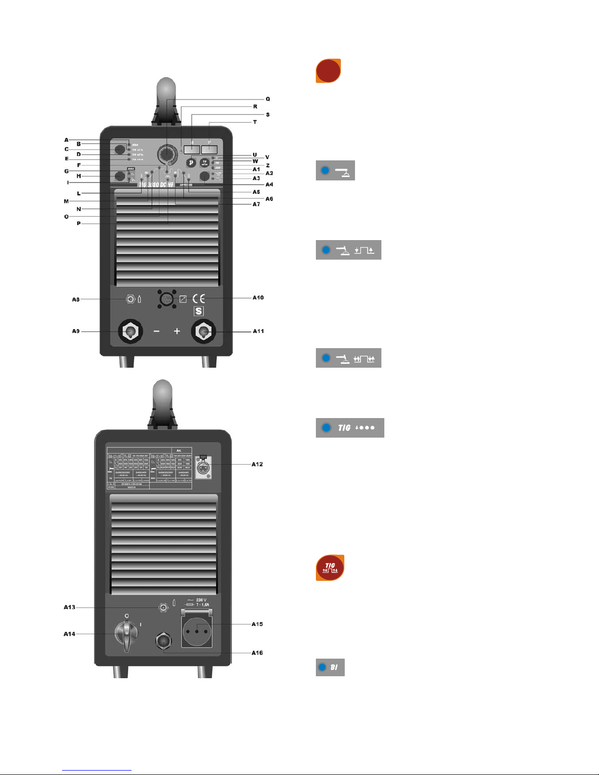
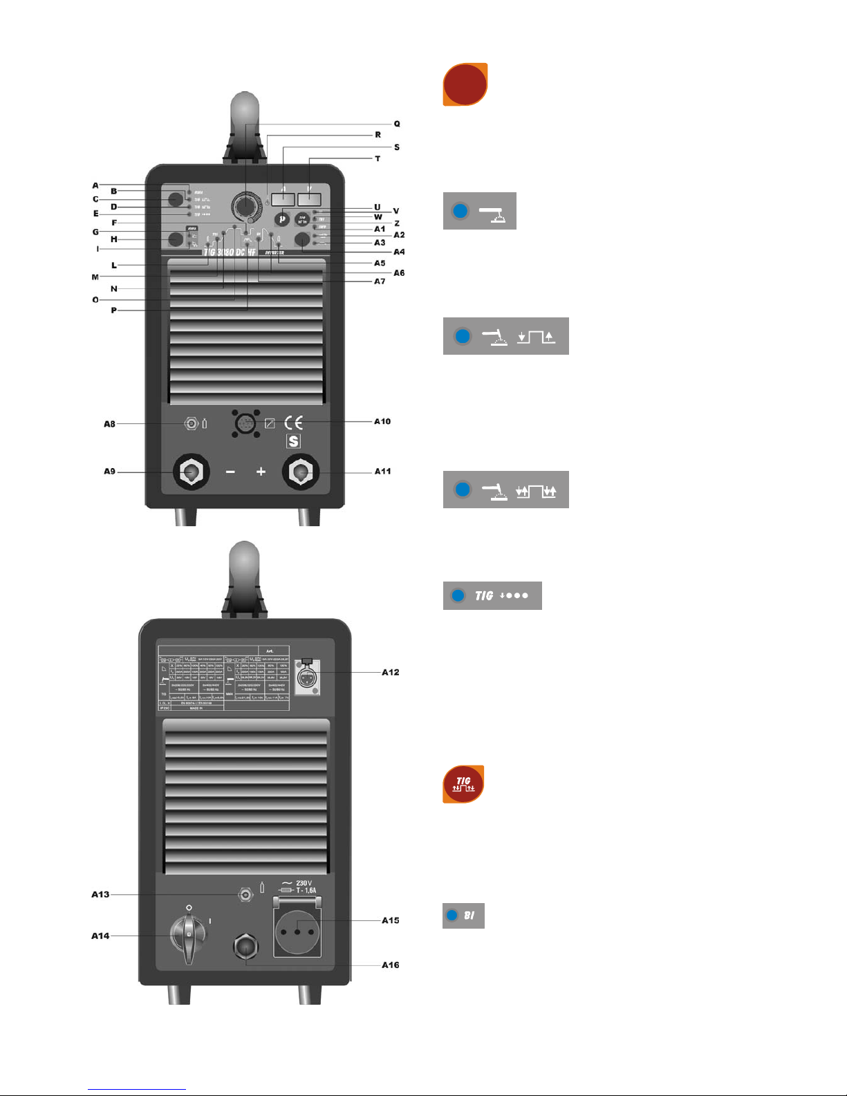
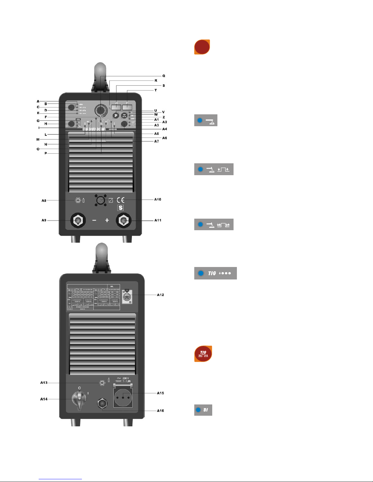
3.2 DESCRIZIONE DELL’APPARECCHIO.
C - Selettore di procedimento e di modo
Tramite questo pulsante avviene la scelta del procedimento
di saldatura (Elettrodo o TIG) e del modo (2 tempi, 4 tempi e
puntatura).
A ogni pressione di questo pulsante si ottiene una nuova
selezione.
L'accensione dei LED in corrispondenza dei simboli
visualizza la Vostra scelta.
LED A - Saldatura ad elettrodo MMA.
Questa macchina può fondere tutti i tipi di elettrodi rivestiti
escluso il tipo cellulosico.
Con questo procedimento la corrente viene regolata tramite
la manopola Q ed è possibile regolare la funzione di "arc
force" (Led I) e di "hot start" (Led G).
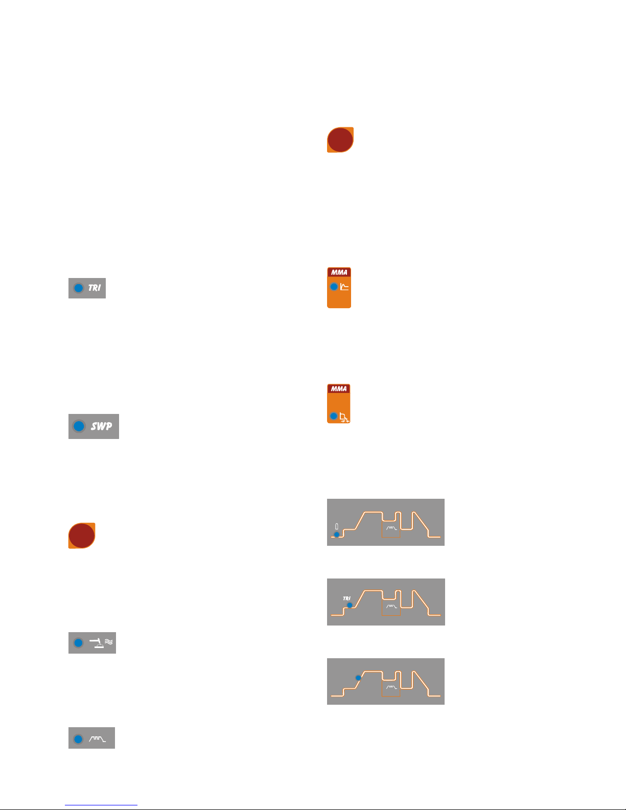
LED B - Saldatura a TIG 2 tempi
(manuale)
Premendo il pulsante della torcia la corrente inizia ad
aumentare ed impiega un tempo corrispondente allo "slope
up" LED N acceso, preventivamente regolato, per
raggiungere il valore regolato con la manopola Q. Quando si
lascia il pulsante la corrente inizia a diminuire ed impiega un
tempo corrispondente allo "slope down" LED A6 acceso,
preventivamente regolato, per ritornare a zero.
LED D - Saldatura a TIG 4 tempi
(automatico)
Questo programma differisce dal precedente perché sia
l'accensione che lo spegnimento vengono comandati
premendo e rilasciando il pulsante della torcia TIG.
LED E - Saldatura a TIG puntatura
(manuale)
Dopo avere scelto la corrente di saldatura LED O e il tempo
di puntatura LED P tramite il selettore H, impostarne i valori
tramite la manopola Q.
Si esegue questo modo di saldatura solo se viene
selezionata l’accensione con alta frequenza LED A2 acceso.
In questa modo di saldatura l'operatore preme il pulsante
della torcia, si accende l'arco, e dopo il tempo di puntatura
regolato, l'arco si spegne automaticamente. Per eseguire il
punto successivo è necessario rilasciare il pulsante torcia e
poi ripremerlo
.
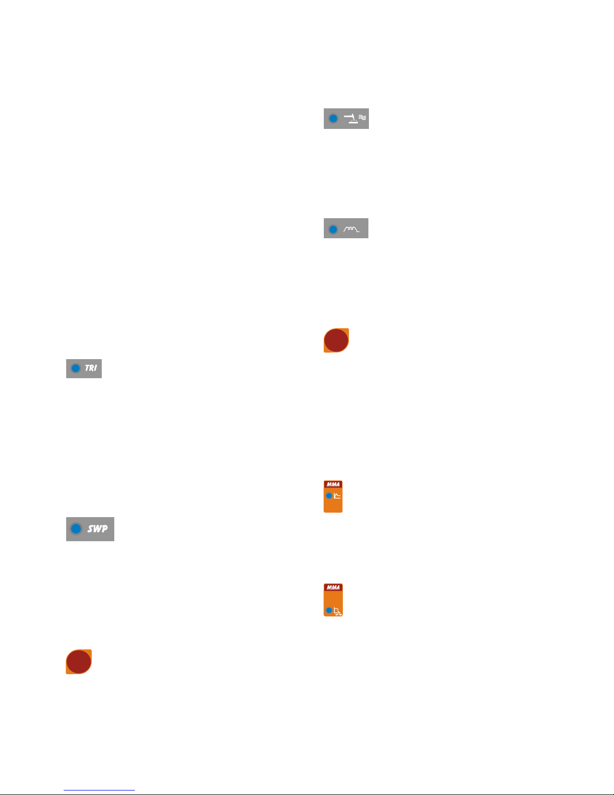
Z - Selettore di modo 4 tempi
Tramite questo pulsante avviene la scelta del modo di
saldatura 4 tempi con due livelli di corrente, 4 tempi con tre
livelli di corrente e 4 tempi speciale SWP.
A ogni pressione di questo pulsante si ottiene una nuova
selezione.
L'accensione dei LED in corrispondenza ai simboli visualizza
la Vostra scelta.
LED V - Saldatura a TIG 4 tempi con due livelli di
corrente (automatico bilevel)
4
Prima di accendere l'arco impostare i due livelli di corrente.
Primo livello: premere il tasto H fino ad accendere il LED O e
regolare la corrente principale con la manopola Q.
Secondo livello: premere il tasto H fino ad accendere il LED
A7 e regolare la corrente con la manopola Q.
Dopo l'accensione dell'arco la corrente inizia ad aumentare
ed impiega un tempo corrispondente allo "slope up" (LED N
acceso), preventivamente regolato, per raggiungere il valore
regolato con manopola Q. Il LED O si accende e il display S
la visualizza.
Se durante la saldatura vi è la necessità di diminuire la
corrente senza spegnere l'arco (per esempio cambio del
materiale d'apporto, cambio di posizione di lavoro, passaggio
da una posizione orizzontale ad una verticale ecc.…)
premere e rilasciare immediatamente il pulsante torcia, la
corrente si porta al secondo valore selezionato, il LED A7 si
accende e O si spegne.
Per tornare alla precedente corrente principale ripetere
l'azione di pressione e di rilascio del pulsante torcia, il LED O
si accende mentre il LED A7 si spegne. In qualsiasi momento
si voglia interrompere la saldatura premere il pulsante torcia
per un tempo maggiore di 0,7 secondi poi rilasciarlo, la
corrente comincia a scendere fino al valore di zero nel tempo
di "slope down", preventivamente stabilito (LED A6 acceso).
Durante la fase di "slope down", se si preme e si rilascia
immediatamente il pulsante della torcia, si ritorna in "slope
up" se questo è regolato ad un valore maggiore di zero,
oppure alla corrente minore tra i valori regolati.
N.B. il termine "PREMERE E RILASCIARE IMMEDIATAMENTE" fa riferimento ad un tempo massimo di 0,5 sec.
LED W - Saldatura a TIG 4 tempi con tre livelli
di corrente (aut o matico trilevel)
Per impostare le tre correnti di saldatura agire come segue:
Premere il selettore H fino ad accendere il LED O quindi
regolare il valore della massima corrente con la manopola Q.
Premere il selettore H fino ad accendere il LED A7 quindi
regolare il valore della corrente intermedia con la manopola
Q.
Premere il selettore H fino ad accendere il LED M quindi
regolare il valore della corrente di accensione con la
manopola Q.
La logica di funzionamento è quella descritta
precedentemente per la saldatura con doppio livello di
corrente LED V.
LED A1 - Saldatura a TIG 4 tempi
programma speciale
Per accendere l'arco premere il pulsante della torcia e
tenendolo
premuto, la corrente inizia ad aumentare con un incremento
fisso. Se si rilascia il pulsante la corrente sale
immediatamente al valore di saldatura LED O. Per terminare
la saldatura premere il pulsante torcia e mantenendolo
premuto la corrente inizia a diminuire con un decremento
fisso. Se si rilascia il pulsante la corrente si azzera
istantaneamente.
A4 - Selettore accensione con alta frequenza e
arco pulsato, on-off
Tramite questo pulsante avviene la scelta del tipo di
accensione (con alta frequenza o per contatto) e del modo
continuo o con arco pulsato. A ogni pressione di questo
pulsante si ottiene una nuova selezione.
L'accensione dei LED in corrispondenza dei simboli
visualizza la Vostra scelta
LED A2 - Accensione con alta frequenza o
per contatto.
Quando il LED è spento per accendere l'arco premere il
pulsante torcia e toccare con l'elettrodo di tungsteno il pezzo
da saldare e rialzarlo. Il movimento deve essere deciso e
rapido.
Quando il LED è acceso per accendere l'arco premere il
pulsante torcia, una scintilla pilota di alta tensione/frequenza
accenderà l'arco.
LED A3 - Arco pulsato on-off
Quando il LED è acceso il modo arco pulsato è attivato.
Da 0,16 fino a 1,1Hz di frequenza di pulsazione il display S
visualizza alternativamente la corrente di picco (principale) e
la corrente di base
I LED O e F si accendono alternativamente; oltre 1,1Hz il
display S visualizza la media delle due correnti e i LED O e F
restano entrambi accesi.
Quando il LED è spento è attivo il modo continuo.
H - Selettore parametri di saldatura MMA e TIG
Premendo questo pulsante si illuminano in successione i
LED.
Attenzione si illumineranno solo i LED che si riferiscono al
modo di saldatura scelto; es. in saldatura TIG continuo non si
illuminerà il LED P che rappresenta la frequenza di
pulsazione.
Ogni LED indica il parametro che può essere regolato tramite
la manopola Q durante il tempo di accensione del LED
stesso.
Dopo 5 secondi dall'ultima variazione il LED interessato si
spegne e viene indicata la corrente di saldatura principale e si
accende il corrispondente LED O.
LED G
Hot start. Si può selezionare tramite il pulsante H solo se è
selezionato il procedimento MMA LED A.
All'accensione di questo led il display S visualizza il tempo,
espresso in secondi, in cui la saldatrice eroga una
sovracorrente per migliorare l'accensione dell'elettrodo. La
regolazione avviene tramite la manopola Q.
LED I
Arc force. Si può selezionare tramite il pulsante H solo se è
selezionato il procedimento MMA LED A. E' una percentuale
della corrente di saldatura. Il display S ne visualizza il valore
e la manopola Q lo regola. In pratica questa sovracorrente
favorisce il trasferimento delle gocce di metallo fuso.
5
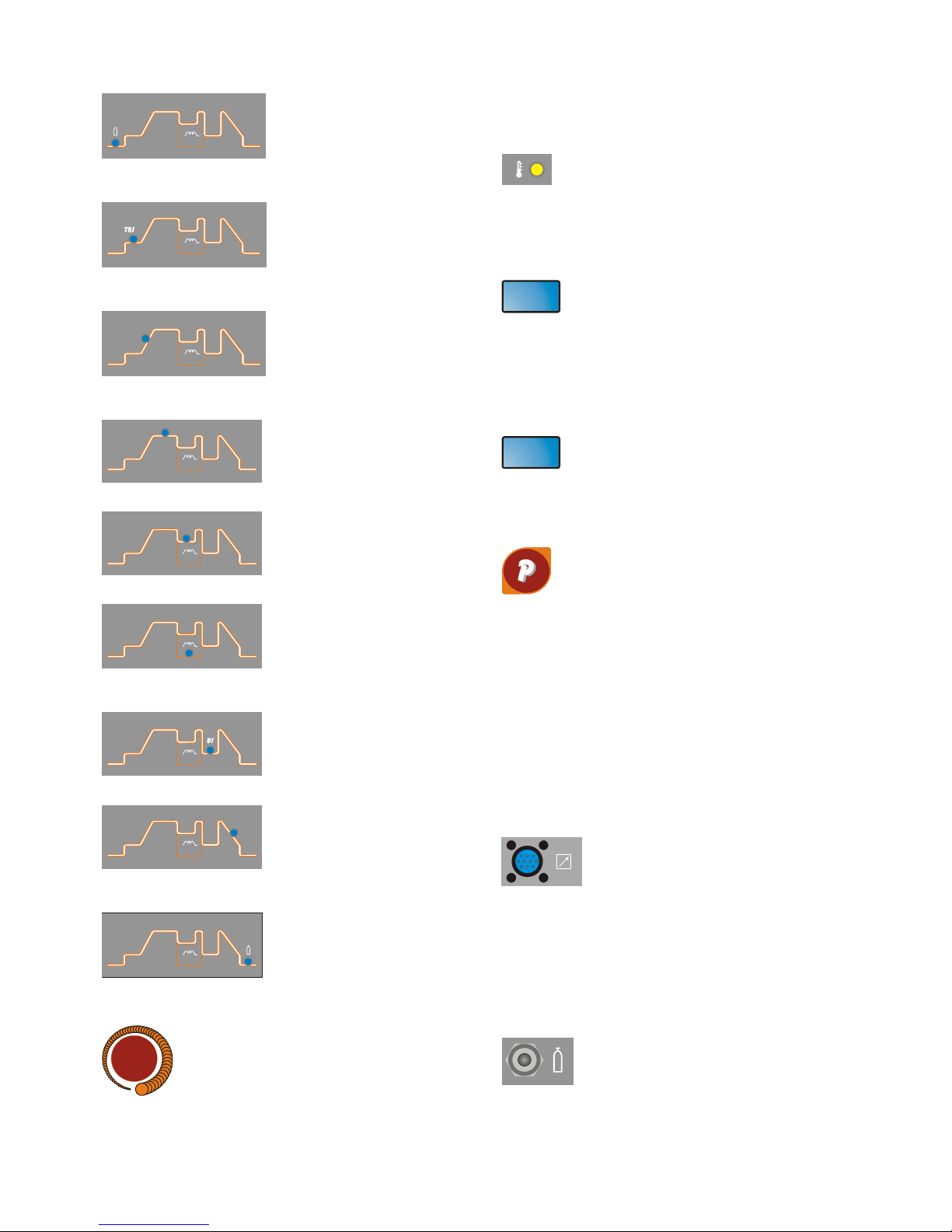
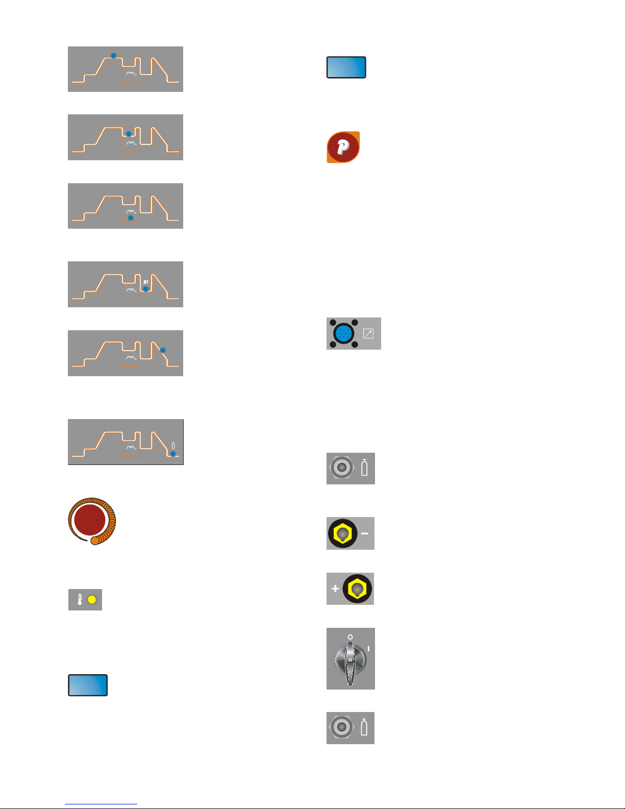
LED L
Pre gas. Regola Il tempo di uscita del gas prima dell'inizio
della saldatura (0,05-2,5 sec.)
LED M
Led corrente di inizio saldatura. E' una percentuale della
corrente di saldatura LED O in modo trilevel.
LED N
Slope up. E' il tempo in cui la corrente, partendo dal minimo,
raggiunge il valore di corrente impostato. (0-10 sec.)
LED O
Corrente di saldatura principale.
LED F
Corrente di base in modo arco pulsato.
LED P
Frequenza di pulsazione da 0,16 a 550 Hz.
I tempi di base e di picco sono uguali.
LED A7
Secondo livello di corrente in modo bilevel.
LED A6
Slope down. E' il tempo in cui la corrente raggiunge il minimo
e lo spegnimento dell'arco. (0-10 sec.)
LED A5
Post gas. Regola il tem po di uscita del gas al termine della
saldatura. (0-30 sec.)
Q - Manopola.
Regola la corrente di saldatura LED O.
Inoltre in abbinamento del pulsante H è possibile regolare
altri parametri di saldatura.
LED R - Protezione termica.
Si accende quando l'operatore supera il fattore di servizio o di
intermittenza percentuale ammesso per la macchina e blocca
contemporaneamente l'erogazione di corrente.
N.B. In questa condizione il ventilatore continua a
raffreddare il generatore.
S – Display
Visualizza la corrente di saldatura e le impostazioni
selezionate con il pulsante H e regolate con la manopola Q.
Nelle procedure di blocco (vedi 2.3.2) della macchina
visualizza:
- tre punti lampeggianti o accesi di continuo.
- le sigle E1 E2 E3 E4
- la sigla H2O
T – Display
Normalmente visualizza la tensione d'arco in relazione al
processo di saldatura in atto.
Nell'impostazione del funzionamento del gruppo di
raffreddamento ne visualizza lo stato.
V
U - Selettore programmi in memoria.
Seleziona e memorizza i programmi.
La saldatrice ha la possibilità di memorizzare nove
programmi di saldatura P01…..P09 e di poterli richiamare
tramite questo pulsante. Inoltre è disponibile un programma
lavoro PL .
Selezione
Premendo brevemente questo pulsante viene visualizzato sul
display S il numero del programma successivo a quello in cui
si sta lavorando. Se questo non è stato memorizzato la scritta
sarà lampeggiante, contrariamente sarà fissa.
Memorizzazione
Una volta selezionato il programma, premendo per un tempo
maggiore di 3 secondi, si memorizzano i dati.
A conferma di questo, il numero del programma, visualizzato
sul display S, terminerà di lampeggiare
A 10 –CONNETTORE 10 POLI.
A questo connettore vanno collegati i
seguenti comandi remoti:
a) pedale
b) torcia con pulsante di start
c) torcia con potenziometro
d) torcia con up/down
e) comando a distanza ecc…
E' disponibile tra i pin 3 e 6 un contatto pulito
che segnala la accensione dell'arco (5A 230V).
A8 –Raccordo ¼ gas.
Vi si connette il tubo gas della torcia di saldatura TIG.
6
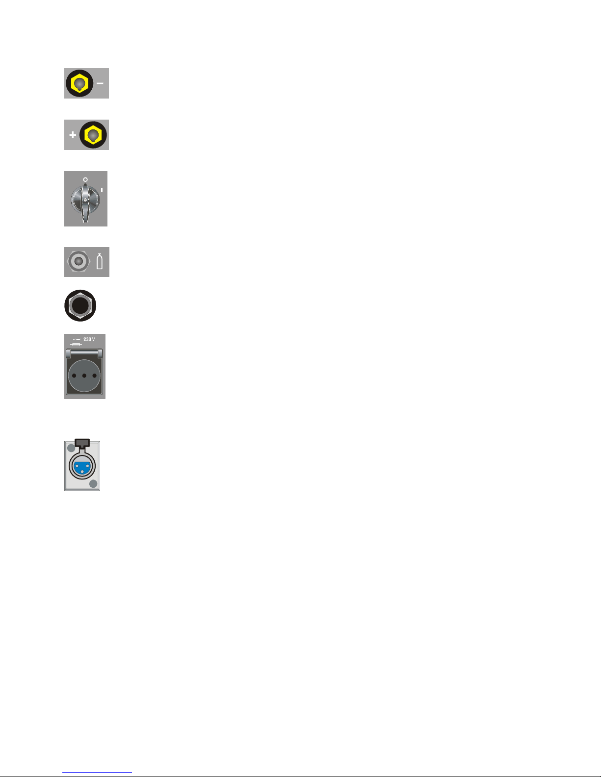
A9
Morsetto di uscita negativo (-)
A11
Morsetto di uscita positivo (+)
A14 –Interruttore.
Accende e spegne la macchina
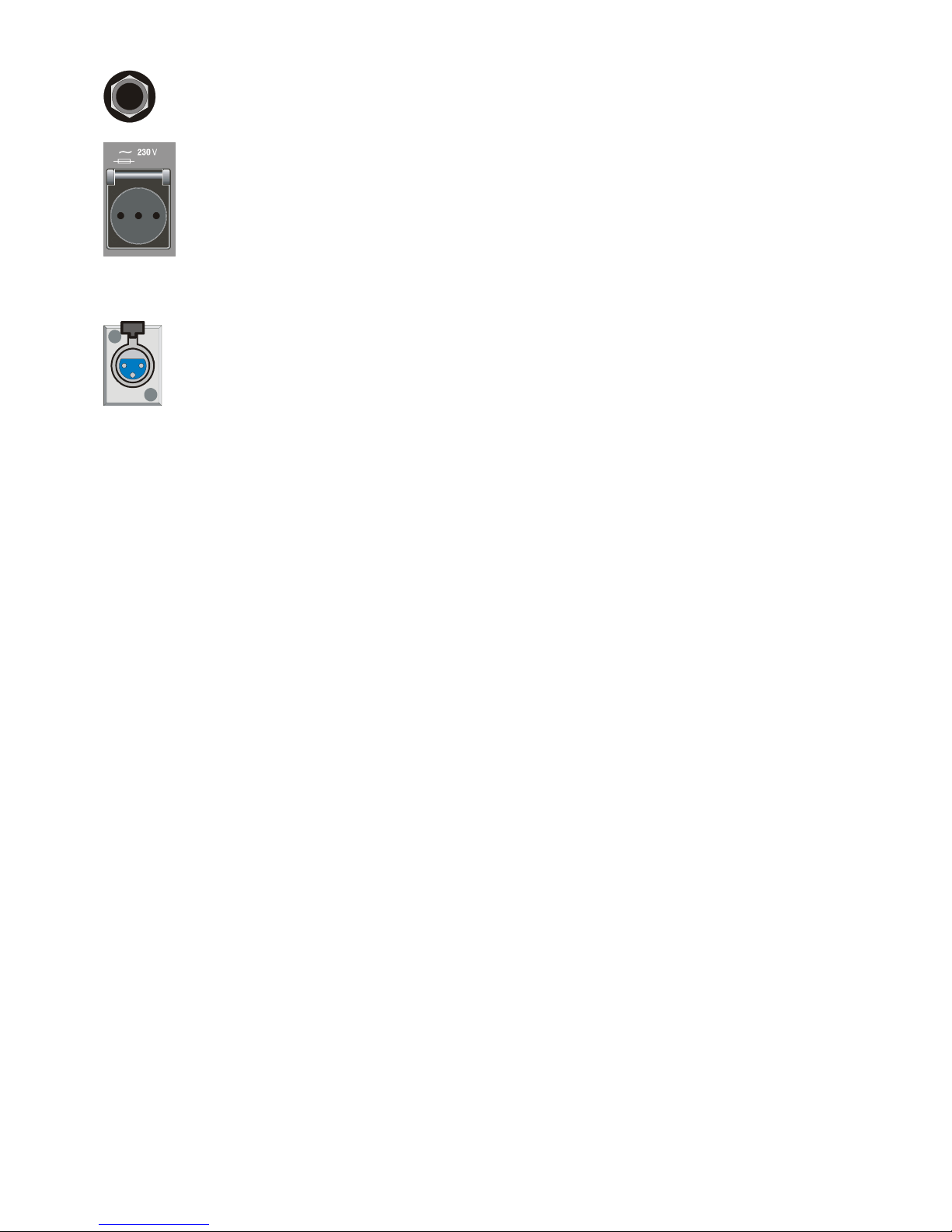
A13 - Raccordo ingresso gas.
A16 - Cavo di alimentazione.
T - 1 , 6 A
A15 – Presa
A cui collegare il gruppo di raffreddamento.
Attenzione: Potenza max: 360VA - Ampere: 1,6.
Non collegare utensili quali smerigliatrici o similari.
A12 – Connettore
Connettore a tre poli a cui va collegato il cavetto del
pressostato del gruppo di raffreddamento.
3.3. NOTE GENERALI
Prima dell'uso di questa saldatrice leggere attentamente le
norme CEI 26/9 - CENELEC HD 407 e CEI 26.11 CENELEC HD 433 inoltre verificare l'integrità dell'isolamento
dei cavi, delle pinze porta elettrodi, delle prese e delle spine e
che la sezione e la lunghezza dei cavi di saldatura siano
compatibili con la corrente utilizzata.
3.4. SALDATURA DI ELETTRODI RIVESTITI (MMA)
- Questa saldatrice è idonea alla saldatura di tutti i tipi di
elettrodi ad eccezione del tipo cellulosico (AWS 6010).
- Assicurarsi che l'interruttore A14 sia in posizione 0, quindi
collegare i cavi di saldatura rispettando la polarità richiesta
dal costruttore di elettrodi che andrete ad utilizzare e il
morsetto del cavo di massa al pezzo nel punto più vicino
possibile alla saldatura assicurandosi che vi sia un buon
contatto elettrico.
- Non toccare contemporaneamente la torcia o la pinza porta
elettrodo ed il morsetto di massa.
- Accendere la macchina mediante l'interruttore A14.
- Selezionare, premendo il pulsante C, il procedimento MMA,
LED A Acceso.
- Regolare la corrente in base al diametro dell'elettrodo, alla
posizione di saldatura e al tipo di giunto da eseguire.
- Terminata la saldatura spegnere sempre l'apparecchio e
togliere l'elettrodo dalla pinza porta elettrodo.
Se si vogliono regolare le funzioni di Hot-start LED G e di
Arc force LED I vedere il paragrafo precedente.
3.5. SALDATURA TIG
Questa saldatrice è idonea a saldare con procedimento TIG
l'acciaio inossidabile, il ferro, il rame.
Collegare il connettore del cavo di massa al polo positivo (+)
della saldatrice e il morsetto al pezzo nel punto più vicino
possibile alla saldatura assicurandosi che vi sia un buon
contatto elettrico.
Collegare il connettore di potenza della torcia TIG al polo
negativo (-) della saldatrice.
Collegare il connettore di comando della torcia al connettore
A10 della saldatrice.
Collegare il raccordo del tubo gas della torcia al raccordo A8
della macchina ed il tubo gas proveniente dal riduttore di
pressione della bombola al raccordo gas A13.
Se si utilizza una torcia raffreddata ad acqua utilizzare il
gruppo di raffreddamento.
Dopo avere riempito di liquido refrigerante il serbatoio
collegare la spina del cavo rete alla presa A15 della
saldatrice, quindi collegare il connettore maschio volante 3
poli al connettore A12.
Accendere la macchina.
Non toccare parti sotto tensione e i morsetti di uscita quando
l'apparecchio è alimentato.
Alla prima accensione della macchina selezionare il modo
mediante i pulsanti C, Z e A4 e i parametri di saldatura
mediante il tasto H e la manopola Q come indicato al
paragrafo 3.2.
Il flusso di gas inerte deve essere regolato ad un valore (in
litri al minuto) di circa 6 volte il diametro dell'elettrodo.
Se si usano accessori tipo il gas-lens la portata di gas può
essere ridotta a circa 3 volte il diametro dell'elettrodo. Il
diametro dell'ugello ceramico deve avere una dimensione da
4 a 6 volte il diametro dell'elettrodo.
Normalmente il gas più usato è l'ARGON perché ha un costo
minore rispetto agli altri gas inerti, ma possono essere usate
anche miscele di ARGON con un massimo del 2%
IDROGENO per la saldatura dell'acciaio inossidabile e ELIO
o miscele di ARGON-ELIO per la saldatura del rame. Queste
miscele au
men
tano il calore dell'arco in saldatura ma sono
molto più costose.
Se si usa gas ELIO aumentare litri al minuto fino a 10 volte il
diametro dell'elettrodo (Es. diametro 1,6 x10= 16 l/min. di
Elio).
Usare vetri di protezione D.I.N. 10 fino a 75A e D.I.N. 11 da
75A in poi.
3.5.1. GRUPPO DI RAFFREDDAMENTO (optional art.
560010)
Se si utilizza una torcia raffreddata ad acqua utilizzare il
gruppo di raffreddamento.
Per selezionare il modo di funzionamento del gruppo di
raffreddamento agire come segue:
1. Selezionare un qualsiasi procedimento TIG.

7
2. Premere il tasto U e mantenendolo premuto premere il
tasto H. Mantenerli premuti fino a quando sul display T
compare la sigla H2O.
3. Selezionare il funzionamento tramite la manopola Q
1 = Gruppo spento,
2 = Funzionamento in continuo,
3 = Funzionamento in automatico.
Per uscire dalla selezione premere brevemente il tasto U.
N.B. Per "Funzionamento automatico" si intende che il
gruppo di raffreddamento si mette in moto alla pressione del
pulsante torcia e smette di funzionare dopo circa 2 minuti dal
rilascio del pulsante torcia.
Attenzione! Se selezionata la saldatura in elettrodo, il
raffreddamento non è acceso e non è selezionabile. E'
normale che alla accensione della macchina il display T
visualizzi, in modo lampeggiante, la sigla H2O.
3.6. MEMORIZZAZIONE
E' possibile memorizzare solo dopo avere saldato.
Il pulsante U, premuto brevemente, effettua una scelta;
premuto per un tempo maggiore di 3 secondi, effettua una
memorizzazione.
Ad ogni accensione, la macchina presenta sempre l'ultima
condizione utilizzata in saldatura.
3.6.1. Memorizzare i dati del programma PL
Utilizzando la macchina per la prima volta.
Alla accensione della macchina il display visualizza la sigla
PL questa, dopo 5 secondi, scompare e viene visualizzata
una corrente di lavoro. Seguire le indicazioni dei paragrafi 3.2
e 3.5 quindi, per memorizzare i dati nel programma P01,
procedere nel seguente modo:
· Premere brevemente il pulsante U comparirà la scritta P01
lampeggiante.
· Premere il pulsante U per un tempo maggiore di 3 secondi
fino a che la sigla P01 smetta di lampeggiare, a questo punto
la memorizzazione è avvenuta.
· Ovviamente se invece di memorizzare nel programma P01
si vuole memorizzare in un programma diverso si premerà il
pulsante U in maniera breve tante volte quante necessarie
per visualizzare il programma desiderato. Alla riaccensione
della macchina viene visualizzato P01.
IL PULSANTE U PREMUTO BREVEMENTE EFFETTUA
UNA SCELTA, PREMUTO PER UN TEMPO MAGGIORE DI
3 SECONDI EFFETTUA UNA MEMORIZZAZIONE.
3.6.2. Memorizzare da un programma libero
L'operatore può modificare e memorizzare un programma
scelto procedendo nel seguente modo:
· Premere il pulsante U in modo breve e scegliere il numero di
programma desiderato.
I programmi liberi hanno la sigla lampeggiante.
· Premere i pulsanti C, Z e A4 e scegliere il procedimento e il
modo di saldatura (paragrafo 3.2).
· Girare la manopola Q ed impostare la corrente di saldatura.
Se è stato scelto il procedimento TIG, attivare il LED A5 (post
gas) tramite il pulsante H e regolare tramite la manopola Q il
v
a
lore desiderato (paragrafo 3.2.)
Se dopo queste regolazioni, necessarie per saldare, si
vogliono regolare i tempi di "slope" o altro agire come
descritto al paragrafo 3.2.
Eseguire una saldatura anche breve e decidere dove
memorizzare
Per memorizzare nel programma scelto precedentemente,
premere il pulsante U per più di 3 secondi fino a che il
numero smette di lampeggiare.
Per memorizzare in un programma diverso, fare la scelta
premendo brevemente il pulsante U quindi premere il
pulsante U per più di 3 secondi.
3.6.3 Memorizzare da un programma memorizzato
Partendo da un programma già memorizzato l'operatore può
modificare i dati in memoria per aggiornare il programma
stesso o per trovare nuovi parametri da memorizzare in un
altro programma.
3.6.3.1 Aggiornare
· Dopo avere acceso la macc hina selezionare i parametri da
modificare e modificarli.
· Eseguire una saldatura anche breve.
· Premere per un tempo maggiore di 3 secondi il tasto U fino
alla conferma della memorizzazione (sigla del programma da
lampeggiante a continua).
3.6.3.2 Memorizzare in un nuovo programma
· Dopo avere acceso la macc hina selezionare i parametri da
modificare e modificarli.
· Eseguire una saldatura anche breve.
· Premere brevemente il selettore U fino alla visualizzazione
del programma da Voi desiderato.
· Premere di continuo il tasto U fino alla conferma della
memorizzazione (sigla del programma da lampeggiante a
continua).
4 COMANDI A DISTANZA
Per la regolazione della corrente di saldatura a questa
saldatrice possono essere connessi i seguenti comandi a
distanza:
Art. 570008 Comando a pedale (usato in saldatura TIG)
Art. 535805 Torcia TIG UP/DOWN.
Art. 535807 Torcia TIG UP/DOWN raffreddata ad acqua.
Art. 530330 +Art. 570006 (usato in saldatura MMA)
Art. 363307 Connessione per collegare contemporaneamente la torcia e il comando a pedale. Con questo accessorio
l’Art. 570008 può essere utilizzato in qualsiasi modo di
saldatura TIG.
I comandi che includono un potenziometro regolano la
corrente di saldatura dal minimo fino alla massima
corrente impostata con la manopola Q.
I comandi con logica UP/DOWN regolano dal minimo al
massimo la corrente di saldatura.
Le regolazioni dei comandi a distanza sono sempre attive nel
programma PL mentre in un programma memorizzato non lo
sono.

8
INSTRUCTION MANUAL FOR ARC WELDING MACHINES
IMPORTANT: READ THIS MANUAL AND THE “SAFETY
RULES” MANUAL CAREFULLY BEFORE INSTALLING,
USING, OR SERVICING THE WELDING MACHINE,
PAYING SPECIAL ATTENTION TO SAFETY RULES.
CONTACT YOUR DISTRIBUTOR IF YOU DO NOT FULLY
UNDERSTAND THESE INSTRUCTIONS.
1 PRECAUTIONS
This machine must be used for welding only. It must not be
used to defrost pipes.
It is also essential to pay special attention to the "SAFETY
RULES" Manual. The symbols next to certain paragraphs
indicate points requiring extra attention, practical advice or
simple information.
This MANUAL and the "SAFETY RULES" MANUAL must be
stored carefully in a place familiar to everyone involved in
using the machine. They must be consulted whenever doubts
arise and be kept for the entire lifespan of the machine; they
will also be used for ordering replacement parts.
2 GENERAL DESCRIPTIONS
2.1 SPECIFICATIONS
This welding machine is a constant current power source
built using INVERTER technology, designed to weld covered
electrodes (not including cellulosic) and for TIG procedures,
with contact starting and high frequency.
2.2 EXPLANATION OF THE TECHNICAL
SPECIFICATIONS LISTED ON THE MACHINE PLATE.
N°
.
Serial number, which must be indicated on any
type of request regarding the welding machine.
Tri-phase static transformer-rectifier frequency
converter.
Drooping-characteristic.
MMA Suitable for welding with covered electrodes.
TIG Suitable for TIG welding.
U0. Secondary open-circuit voltage
X. Duty cycle percentage. % of 10 minutes during
which the welding machine may run at a certain
current without overheating.
I2. Welding current
U2. Secondary voltage with current I2
U1. Rated supply voltage
3- 50/60Hz 50- or 60-Hz tri-phase power supply
I1 max. This is the maximum value of the absorbed
current.
I1 eff. This is the maximum value of the actual current
absorbed, considering the duty cycle.
IP23C Protection grade of the housing, approving the
equipment as suitable for use outdoors.
C: The additional letter C means that the equipment
is protected against access to the live parts of the
power circuit by a tool (diameter 2,5 mm).
Suitable for hazardous environments.
NOTES: the welding machine has also been designed for
use in environments with a pollution rating of 3. (See IEC
664).
2.3 DESCRIPTION OF PROTECTIVE DEVICES
2.3.1. Thermal protection
This machine is protected by a temperature probe, which
prevents the machine from operating if the allowable
temperatures are exceeded. Under these conditions the fan
keeps running and the LED R lights.
2.3.2. Block protections
This welding machine is equipped with various safety
devices that stop the machine before it can suffer damage.
The welding machine may operate within the following
voltage ranges:
For rated voltage 208/220/230V, from 175 to 270V
For rated voltage 400/440V, from 340 to 490V
Caution: if the supply voltage does not fall between the
above values, no LED will light and the fan is powered.
If the phases are not properly connected, 3 light points will
appear (steadily lit) on the display S when the machine is
started.
If, with the machine on, the voltage falls below 175 V (U1 =
230V) or 340 V (U1 = 400V), the display S will show the
abbreviation E3.
If, with the machine on, the voltage rises above 275 V (U1 =
230V) or 490 V (U1 = 400V), the display S shows the
abbreviation E4.
In this case turn off the machine, restore the proper voltage
and restart. If the problem has been corrected, the welding
machine will begin operating again.
If, with the machine on, the display S shows the message
E2 or E1, check the supply voltage of the machine; if it is
correct, the machine requires technical service.
If a low water level is detected for the cooling unit the
abbreviation H2O flashes on the display S.
3. INSTALLATION
Make sure that the supply voltage matches the voltage
indicated on the specification plate of the welding machine.
The capacity of the overload cut-out switch or fuses installed
in series with the power supply must be equivalent to the
absorbed current I1 of the machine.
WARNING! Extension cords of up to 30m must have a
cross-section of at least 2.5 mm2.
3.1 START-UP
Only skilled personnel should install the machine. All
connections must be carried out according to current
regulations, and in full observance of safety laws (regulation
CEI 26-10 -CENELEC HD 427).
9
3.2 DESCRIPTION OF THE EQUIPMENT.
C – Procedure and mode selector switch
This push-button selects the welding procedure (MMA or
TIG) and mode (2-step, 4-step and spot welding).
The selection changes each time the button is pressed.
The LEDs light next to the various symbols to display your
choice.
A LED – MMA (Manual Metal Arc) welding.
This machine can melt all types of coated electrodes, except
for cellulose.
With this process the current is adjusted using the knob Q,
and it is possible to adjust the "arc force" (LED I) and "hot
start" function (LED G).
B LED – 2-step TIG welding
(manual)
When the torch trigger is pressed, the current begins to
increase over the previously set “slope up” time (N LED on),
until it reaches the value set by means of the Q knob. When
the trigger is released, the current begins to drop over the
previously set “slope down” time (A6 LED on), until it goes
back to zero.
D LED – 4-step TIG welding
(automatic)
This program differs from the previous one in that the arc is
both started and extinguished by pressing and releasing the
TIG torch trigger.
LED E – TIG spot-welding LED
(manual)
After selecting the welding current (LED O) and the spot
welding time (LED P) using the selector switch H, set the
values using the knob Q.
This welding mode is to be used only if start-up with high
frequency is selected (LED A2 lit). In this welding mode, the
operator presses the torch trigger, the arc lights, and after
the set spot welding time the arc shuts off automatically. To
do the next spot, you must therefore release the torch
trigger and press it again.
Z – 4-step mode selector switch
This push-button selects the welding mode: 4-step with dual
current level, 4-step with with three levels of current and 4step SWP special program.
The selection changes each time the button is pressed.
The LEDs light next to the various symbols to display your
choice.
LED V - 4-step TIG welding with dual current
level, (automatic bilevel).
Set the two current levels before lighting the arc:
First level: press the H key until the LED O lights, and adjust
the main current using the knob Q.
Second level: press the H key until the LED A7 lights, and
adjust the main current using the knob Q.
10
When the torch trigger is pressed, the current begins to
increase over the previously set "slope up" time (LED N lit),
until it reaches the value set by means of the knob Q. The
LED O lights and appears on the display S.
Should it be necessary to reduce the current during welding,
without shutting of the arc (for instance when changing the
welding material or working position, moving from horizontal
to upright, etc.…), press and immediately release the torch
trigger: the current will switch to the second value selected,
the LED A7 will light and O will go off.
To return to the previous main current, press and release the
torch trigger once again. The LED O will light, and the LED
A7 will go off. To stop welding at any time, simply hold down
the torch trigger for more than 0.7 seconds, then release.
The current begins to fall to zero within the previously set
"slope down" time interval (LED A6 lit).
If you press and immediately release the torch trigger during
the "slope down" phase, you will return to "slope up" if it is set
to greater than zero, or to the lesser current value of those
set.
NOTE: The expression "PRESS AND IMMEDIATELY
RELEASE" refers to a maximum time of 0.5 seconds.
LED W - 4-step TIG welding with three levels of
current (automatic trilevel).
To set the three welding currents, proceed as follows:
Press the selector switch H until the LED O lights, then adjust
the maximum current value using the knob Q.
Press the selector switch H until the LED A7 lights, then
adjust the intermediate current value using the knob Q.
Press the selector switch H until the LED M lights, then adjust
the starting current value using the knob Q.
The operating logic is the same as previously described for
welding with dual current level LED V.
LED A1 - 4-step TIG welding with special
program
To light the arc, press the torch trigger and hold it down; the
current begins to increase at a fixed rate. If the torch trigger
is released, the current immediately rises to the welding
value (LED O). To stop welding, press the torch trigger and
hold it down; the current begins to drop at a fixed rate. The
current immediately returns to zero if the trigger is released.
LED A4 - Selector switch for high frequency
ignition and pulsed arc mode, on-off
This push-button selects the ignition type (with high
frequency or by contact) and the continuous or pulsed arc
mode. The selection changes each time the button is
pressed.
The LEDs light next to the various symbols to display your
choice.
LED A2 - Ignition with high frequency or by
contact.
When the LED is off, to start the arc press the torch trigger
and touch the tungsten electrode to the workpiece, then lift it.
This move must be quick and sharp.
When the LED is on, to start the arc, press the torch trigger:
a high voltage/frequency pilot spark will start the arc.
LED A3 - Pulsed arc, on-off
When the LED is on, the pulsed arc mode is activated.
From a pulse frequency of 0.16 to 1.1Hz, the S display
alternately shows the peak (main) current and the base
current
The O and F LEDs light alternately: beyond 1.1 Hz the S
display shows the mean of the two currents and the O and F
LEDs both remain on.
When the LED is off, the continuous mode is activated.
H – MMA and TIG welding parameters selector
switch
Pressing this button will light the LEDs in sequence:
Warning: only those LEDs which refer to the chosen
welding mode will light; e.g. in continuous TIG welding the
P LED, representing the pulse frequency, will not light.
Each LED indicates the parameter, which may be adjusted
via the Q knob during the lighting time of the LED.
5 seconds after the last variation, the LED involved will light
off; the main welding current will then be displayed and the
corresponding O LED will light.
LED G
Hot-Start LED. May be selected via the button H only if
MMA welding is selected (LED A).
This LED lights to indicate that the display S displays the
time, expressed in seconds, during which the welding
machine delivers an overcurrent to improve electrode
starting. It may be adjusted using the knob Q.
LED I
Arc-force LED. May be selected via the button H only if
MMA welding is selected LED A.
It is a percentage of the welding current. The display S
displays its value, and the knob Q adjusts it. This
overcurrent essentially aids in the transfer of drops of molten
metal.
LED L
Pre-gas LED. Adjustment 0.05-2.5 seconds. Gas output
time before starting welding.
LED M
Welding start current LED. This is a percentage of the
welding current LED O in three levels mode.
LED N
Slope up LED. This is the time in which the current, starting
from the minimum, reaches the set current value. (0-10 sec.)
11
LED O
Main welding current LED .
LED F
Base current in pulsed arc mode.
LED P
Pulse frequency LED (0.16-550 Hz).
The peak and base times are equal.
LED A7
Second level of current in dual level mode.
LED A6
Slope down. This is the time during which the current
reaches its minimum value and the arc is extinguished (0-10
sec.).
LED A5
Post gas. Adjusts the gas flow time at the end of welding (030 sec.).
Q - Knob
Adjusts the welding current - LED O.
In addition, combined with the H push-button, it adjusts other
welding parameters
LED R - Thermal protection.
It lights when the operator exceeds the duty cycle or
percentage intermittence allowed for the machine and
simultaneously stops the current output.
N.B. Under this condition the fan goes on cooling the
power source.
S – Display
Displays the welding current and the settings selected by
means of the push-button H and adjusted via the knob Q.
In the machine blocking procedures (see 2.3.2), it displays:
- Three flashing or steadily lit points
- The abbreviations E1 E2 E3 E4
- The abbreviation H20
T – Display
Normally displays the arc voltage in relation to the current
welding process.
When setting the cooling unit operation, it displays the
status of this unit.
V
U - Selector switch for programs in memory.
Selects and saves the programs in memory.
The welding machine can save nine welding programs
P01…..P09 and call them up via this button. A working
program PL is also available.
Selecting
When this push-button is pressed briefly, the S display
shows the program number next to the one in use. If this
has not been saved, the message will flash, otherwise it
remains steady.
Saving
Once the program has been selected, hold down for more
than 3 seconds to save the data in memory.
To confirm this, the program number on the S display will
stop flashing
A 10 – 10-pin connector
The following remote controls are to be connected to this
connector:
a) foot control
b) torch with start button
c) torch with potentiometer
d) torch with up/down
e) remote control, etc.
A clean contact is available between pins 3 and 6 to signal
when the arc is lit (5A 230V).
A8 – 1/4 GAS FITTING
This is where the gas hose of the TIG welding torch is to be
connected.
A9
Negative output terminal (-)
A11
Positive output terminal (+)
A14 – Switch
Turns the machine on and off
A13 - Gas intake fitting
12
A16 - Power supply cable.
T - 1,6A
A15 – Socket
To which to connect the cooling unit.
Caution: Max. power: 360VA - Amps: 1.6.
Do not connect tools such as polishers or similar
A12 – Connector
Three-pin connector to which to connect the wire of the
cooling unit pressure switch.
3.3. GENERAL NOTES
Before using this welding machine, carefully read the
standards CEI 26/9 - CENELEC HD 407 and CEI 26.11 CENELEC HD 433. Also make sure the insulation of the
cables, electrode clamps, sockets and plugs are intact, and
that the size and length of the welding cables are compatible
with the current used.
3.4. MMA WELDING (MANUAL METAL ARC)
- This welding machine is suitable for welding all types of
electrodes, with the exception of cellulosic (AWS 6010)*.
- Make sure that the switch A14 is in position 0, then connect
the welding cables, observing the polarity required by the
manufacturer of the electrodes you will be using; also
connect the damp of the ground cable to the workpiece, as
close to the weld as possible, making sure that there is good
electrical contact.
- Do NOT touch the torch or electrode holder simultaneously
with the earth clamp.
-Turn the machine on using the switch A14.
- Select the MMA procedure by pressing the button C: LED A
lit.
- Adjust the current based on the diameter of the electrode,
the welding position and the type of joint to be made.
- Always remember to shut off the machine and remove the
electrode from the clamp after welding.
If you wish to adjust the Hot-start (LED G) and Arc force
functions (LED I), see the previous paragraph.
3.5 . TIG WELDING
This welding machine is suitable for welding stainless steel,
iron, or copper using the TIG procedure. Connect the earth
cable connector to the positive pole (+) of the welding
machine, and the clamp to the workpiece as close as
possible to the welding point, making sure there is good
electrical contact.
Connect the power connector of the TIG torch to the negative
pole (-) of the welding machine.
Connect the torch connector to the welding machine
connector A10.
Connect the torch gas hose fitting to the fitting A8 on the
machine, and the gas hose from the cylinder pressure
regulator to the gas fitting A13 on the rear panel.
If using a water-cooled torch, use the cooling unit.
After filling the tank with coolant, connect the plug of the
mains cable to the socket A15 of the welding machine, then
connect the 3-pin male patch connector to the connector
A12.
Turn on the machine.
Do not touch live parts and output terminals while the
machine is powered.
The first time the machine is turned on, select the mode
using the push-buttons C, Z and A4 and the welding
parameters by means of the key H and the knob Q as
described in paragraph 3.2 The flow of inert gas must be set
to a value (in liters per minute)
approximately
6 times the
diameter of the electrode.
If you are using gas-lens type accessories, the gas
throughput may be reduced to approximately 3 times the
diameter of the electrode. The diameter of the ceramic
nozzle must be 4 to 6 times the diameter of the electrode.
The most commonly used gas is normally ARGON, because
it is less costly than other inert gases, but you may also use
blends of ARGON with a maximum of 2% HYDROGEN for
welding stainless steel, and HELIUM or ARGON-HELIUM
blends for welding copper.
These blends increase the heat of the arc while welding, but
are much more expensive.
If you are using HELIUM gas, increase the liters per minute
to 10 times the diameter of the electrode (Ex. diameter 1.6 x
10= 16 It./min of Helium).
Use D.I.N. 10 protective glasses for up to 75A, and D.I.N. 11
from 75A up.
3.5.1 Cooling unit (optional art. 560010).
When using a water-cooled torch, use the cooling unit.
To select the cooling unit working mode, proceed as follows:
1. Select any TIG procedure.
2. Press the key U and while holding it down, press the
key H. Hold both keys down until the display T reads
H2O.
3. Select the working mode with the knob Q
1 = Unit off,
2 = Continuous operation,
3 = Automatic operation.
To exit the selection menu briefly press U.
N.B. "Automatic operation" means that the cooling unit is
started when the torch button is pressed and stopped after
approximately 2 minutes from releasing the torch button.
Caution! If electrode welding is selected, cooling is not
active and cannot be selected. Upon machine power-on, the
display T may show the flashing message H2O.
3.6. SAVING
You may save parameters only after welding.
Pressing the push-button U briefly makes a selection; held
down for more than 3 seconds, it saves the data.
Each time it is turned on, the machine always shows the last
welding condition used.
3.6.1. Saving data from the PL program
Using the machine for the first time
When the machine is turned on, the display shows the
symbol PL; this disappears after 5 seconds, and a working
current is displayed. Follow the instructions in paragraphs
3.2 and 3.5, then proceed as follows to save the data in the
program P01:
• Briefly press the push-button U the message P01 will
appear flashing.
• Press push-button U for more than 3 seconds, until the
symbol P01 stops flashing: at this point, the data have been
saved.
• Obviously, if you wish to save in a program other than P01,

13
you should briefly press the push-button U as many times as
necessary to display the desired program. P01 will be
displayed the next rime the machine is turned on.
PRESSING THE U PUSH-BUTTON BRIEFLY MAKES A
SELECTION, WHILE HOLDING IT DOWN FOR MORE
THAN 3 SECONDS SAVES THE DATA.
3.6.2. Save from a free program
The operator may edit and save a selected program by
proceeding as follows:
• Press the push-button U briefly and select the desired
program number.
• The symbol of free programs is flashing.
• Press the push buttons C, Z and A4 and select the welding
procedure and mode (paragraph 3.2).
• Turn the knob Q and set the welding current.
• If the TIG procedure has been selected, activate the LED
A5 (post gas) by means of the push-button H, and set the
desired value via the knob Q (paragraph 3.2.)
• If you wish to adjust the "slope" times or other parameters,
after making these adjustments which are necessary in
order to weld, follow the steps described in paragraph 3.2.
• Weld, even briefly, and decide where to save
• To save in the previously selected program, press the
button U for more than 3 seconds, until the number stops
flashing.
• To save in a different program, make your selection by
briefly pressing the push-button U, then hold down the push
button U for more than 3 seconds.
3.6.3. Save from a saved program
Beginning with a previously saved program, the operator may
edit the data in memory to update the program itself, or to
find new parameters to save in another program.
3.6.3.1 Update
• Alter turning on the machine, select the parameters to be
edited and edit them.
• Weld, even briefly.
• Hold down the U button for more than 3 seconds, until the
save is confirmed (program symbol changes from flashing to
steady).
3.6.3.2 Save in a new program
• After turning on the machine, select the parameters to be
edited and edit them.
• Weld, even briefly.
• Briefly press the selector U until the desired program is
displayed.
• Hold down the U button until the save is confirmed
(program symbol changes from flashing to steady).
4. REMOTE CONTROLS
The following remote controls may be connected to adjust the
welding current for this welding machine:
Item 570008 Foot control (used in TIG welding)
Item 535805 TIG UP/DOWN torch.
Item 535807 TIG UP/DOWN water cooled torch.
Item 530330+ltem 570006 (used in MMA welding)
Item 363307 Connection to simultaneously connect the torch
and the pedal control.
Item 570008 may be used in any TIG welding mode with this
accessory.
Remote controls that include a potentiometer regulate
the welding current from the minimum to the maximum
current set via the knob Q.
Remote controls with UP/DOWN Iogic regulate the
welding current from the minimum to the maximum.
The remote control settings are always active in the PL
program, w
h
ile they are not active in a saved program.

1
BEDIENUNGSANLEITUNG FÜR LICHTBOGENSCHWEISSMASCHINEN
WICHTIG:
VOR INSTALLATION UND GEBRAUCH DIESER
SCHWEISSMASCHINE BZW. VOR AUSFÜHRUNG VON
BELIEBIGEN WARTUNGSARBEITEN, DIESES HANDBUCH
UND DAS HANDBUCH “SICHERHEITSVORSCHRIFTEN
FÜR DEN GERÄTEGEBRAUCH” AUFMERKSAM LESEN.
DABEI IST DEN SICHERHEITSNORMEN BESONDERE
BEACHTUNG ZU SCHENKEN. BITTE WENDEN SIE SICH
AN IHREN DISTRIBUTOR, WENN IHNEN AN DIESER
ANLEITUNG ETWAS UNKLAR IST.
1 VORWORT
Diese Maschine darf nur zur Ausführung von Schweißarbeiten
verwendet werden. Sie darf nicht zum Enteisen von Rohren
benutzt werden.
Des weiteren ist dem Handbuch, das die
Sicherheitsvorschriften enthält, größte Beachtung zu
schenken.
Die Symbole neben den einzelnen Paragraphen weisen auf
Situationen, die größte Aufmerksamkeit verlangen, Tipps oder
einfache Informationen hin.
Die beiden Handbücher sind sorgfältig an einem Ort
aufzubewahren, der allen Personen, die mit dem Gerät zu tun
haben, bekannt ist. Sie sind immer dann heranzuziehen, wenn
Zweifel bestehen. Die beiden Handbücher haben die Maschine
über ihre ganze Lebensdauer zu “begleiten” und sind bei der
Bestellung von Ersatzteilen heranzuziehen.
2 ALLGEMEINE BESCHREIBUNG
2.1. EIGENSCHAFTEN
Bei dieser Schweißmaschine handelt es sich um eine
Konstant-Gleichstromquelle mit INVERTER-Technologie, die
zum WIG-Schweißen mit umhüllten Elektroden
(Zelluloseumhüllungen ausgenommen) und mit Berührungsund Hochfrequenzzündung entwickelt wurde. Nicht zum
Entfrosten von Rohrleitungen verwenden.
2.2. ERLÄUTERUNG DER TECHNISCHEN DATEN
Nr. Seriennummer; sie muß bei allen Anfragen zur
Schweißmaschine stets angegeben werden.
Statischer Dreiphasen-Frequenzumrichter
Transformator-Gleichrichter.
Fallende Kennlinie.
MMA Geeignet zum Schweißen mit umhülten
Elektroden.
WIG Geeignet zum WIG-Schweißen.
U0 Leerlaufspannung Sekundärseite.
X Einschaltdauer. Die Einschaltdauer ist der auf
eine Spieldauer von 10 Minuten bezogene
Prozentsatz der Zeit, die das Gerät bei einer
bestimmten Stromstärke arbeiten kann, ohne
sich zu überhitzen.
I2. Schweißstrom.
U2 Sekundärspannung bei Schweißstrom I2.
U1 Bemessungsspeisespannung.
3 ~ 50/60Hz Dreiphasen-Stromversorgung 50 oder 60 Hz.
I1 max. Dies ist der Höchstwert der Stromaufnahme.
I1 eff. Dies ist der Höchstwert der effektiven
Stromaufnahme bei Berücksichtigung der
relativen Einschaltdauer.
IP23C Schutzart des Gehäuses, die bescheinigt, daß
das Gerät im Freien betrieben werden darf.
C: Der zusätzliche Buchstabe C gibt an, dass das
Gerät gegen das Eindringen eines Werkzeugs
(Durchmesser 2,5 mm) in den Bereich der aktiven
Teile des Stromversorgungskreises geschützt ist.
Geeignet zum Betrieb in Umgebungen mit
erhöhter Gefährdung.
ANMERKUNGEN: Das Gerät ist außerdem für den Betrieb in
Umgebungen mit Verunreinigungsgrad 3 konzipiert. (Siehe IEC
664).
2.3. BESCHREIBUNG DER SCHUTZEINRICHTUNGEN
2.3.1. Thermischer Schutz
Dieses Gerät wird durch einen Temperaturfühler geschützt, der,
wenn die zulässigen Temperaturen überschritten werden, den
Betrieb der Maschine sperrt. In diesem Zustand bleibt der Lüfter
eingeschaltet und die LED R leuchtet auf.
2.3.2. Schutzverriegelungen
Diese Schweißmaschine verfügt über verschiedene
Schutzeinrichtungen, die die Maschine ausschalten, bevor sie
Schaden nehmen kann.
Die Schweißmaschine kann innerhalb der folgenden
Spannungsbereiche arbeiten:
Für Nennspannung 208/220/230V: von 175V bis 270V.
Für Nennspannung 400/440V: von 340V bis 490V.
Achtung: Wenn die Netzspannung nicht innerhalb der o.g.
Werte liegt, leuchtet keine LED auf, doch der Ventilator wird
gespeist.
Wenn die Phasen nicht richtig angeschlossen sind, erscheinen
im Moment der Einschaltung der Maschine auf dem Display S
drei ständig leuchtende Punkte.
Wenn die Spannung bei eingeschalteter Maschine den Wert
von 175 V (U1 = 230 V) bzw. von 340 V (U1 = 400 V)
unterschreitet, erscheint auf dem Display S das Kürzel E3.
Wenn die Spannung bei eingeschalteter Maschine den Wert
von 275 V (U1 = 230 V) bzw. von 490 V (U1 = 400 V)
überschreitet, erscheint auf dem Display S das Kürzel E4.
In diesen Fällen muss man die Maschine ausschalten und für
die richtige Versorgungsspannung sorgen; dann die Maschine
wieder einschalten. Wenn das Problem behoben wurde, arbeitet
die Schweißmaschine wieder ordnungsgemäß.
Wenn bei eingeschalteter Maschine auf dem Display S das
Kürzel E2 oder E1 erscheint, die Versorgungsspannung der
Maschine kontrollieren. Sollte die richtige Versorgungsspannung vorliegen, bedarf die Maschine einer Reparatur.
Wenn der Wasserpegel im Kühlaggregat zu niedrig ist,
erscheint auf Disp lay S das Kürzel H2O.
3. INSTALLATION
Sicherstellen, daß die Speisespannung der auf dem
Leistungsschild der Schweißmaschine angegebenen
Bemessungsspannung entspricht.
Der Bemessungsstrom des in Reihe mit der Speisung
geschalteten thermomagnetischen Schalters oder der
Sicherungen muß gleich dem von der Maschine
aufgenommenen Strom I1 sein.
ACHTUNG! Die Verlängerungen bis 30 m müssen einen
Querschnitt von mindestens 2,5 mm
2
haben.
3.1. INSTALLATION
Die Installation der Maschine muß durch Fachpersonal erfolgen.
Alle Anschlüsse müssen nach den geltenden Bestimmungen
15
und unter strikter Beachtung der Unfallverhütungsvorschriften
ausgeführt werden (Norm CEI 26-10 CENELEC HD 427).
3.2 BESCHREIBUNG DES GERÄTS
C – Schweißverfahren- und Betriebsarten-
Wahlschalter
Mit diesem Drucktaster wählt man das Schweißverfahren
(Elektroden- oder WIG-Schweißen) und die Betriebsart (2-Takt,
4-Takt und Punktschweißen).
Jede Betätigung dieses Drucktasters bewirkt eine neue
Einstellung.
Die von Ihnen getroffene Wahl wird durch das Aufleuchten der
LEDs neben den jeweiligen Symbolen angezeigt.
A – LED Elektrodenschweißen (MMA)
Diese Maschine kann alle Arten von Elektroden mit Ausnahme
von Elektroden mit Zelluloseumhüllung schmelzen.
Bei diesem Verfahren wird der Strom mit dem Regler Q
eingestellt; außerdem kann man die Funktionen "Arc Force"
(LED I) und "Hot Start" (LED G) regeln.
B – LED WIG-Schweißen – 2-Takt
(Handbetrieb)
Drückt man den Brennertaster, steigt der Strom in der zuvor
eingestellten Zeit "slope up" an (LED N leuchtet), bis der mit
dem Regler Q eingestellte Wert erreicht wird. Löst man den
Brennertaster, sinkt der Strom in der zuvor eingestellten Zeit
“slope down” (LED A6 leuchtet) auf den Wert 0.
D – LED WIG-Schweißen – 4-Takt
(Automatikbetrieb)
Dieses Programm unterscheidet sich von dem vorherigen darin,
dass sowohl die Zündung als auch das Löschen durch
Betätigen und Lösen des WIG-Brennertasters gesteuert
werden.
E - LED Punktschweißen (Handbetrieb).
Nach Wahl des Schweißstroms (LED O) und der
Punktschweißzeit (LED P) mit Wahltaster H die Werte mit
Regler Q einstellen.
Dieses Schweißverfahren ist nur bei Wahl der HochfrequenzZündung möglich (LED A2 leuchtet). Drückt man bei diesem
Schweißverfahren den Brennertaster, entzündet sich der
Lichtbogen und erlischt nach Ablauf der eingestellten
Punktschweißzeit automatisch wieder. Für die Ausführung der
nächsten Punktschweißung muss man den Brennertaster
loslassen und dann erneut drücken.
Z - Wahltaster 4-Takt Schweißverfahren
Mit diesem Drucktaster wählt man das Schweißverfahren:
Zweiwertschaltung, 4-Takt, Dreiwertschaltung, 4-Takt, 4-Takt
Sonderprogramm SWP.
Jede Betätigung entspricht einer Wahl. Die getroffene Wahl wird
durch das Aufleuchten der LEDs neben den jeweiligen
Symbolen angezeigt.
V – LED WIG-Schweißen mit Zweiwertschaltung, 4-
Takt (Automatikbetrieb)
Vor dem Zünden des Lichtbogens müssen die zwei
verschiedenen Schweißströme eingestellt werden:
 Loading...