

Elettro CF Pro MIG 277, Pro MIG 278, Pro MIG 279 Instruction Manual
I MANUALE DI ISTRUZIONE PER GENERATORE PER SALDATRICE A FILO ................... 3
GB INSTRUCTION MANUAL FOR MIG-MAG WELDING POWER SOURCE......................... 6
D BETRIEBSANLEITUNG FÜR DRAHTSCHWEISSSTROMQUELLE ................................ 9
F MANUEL D'INSTRUCTIONS POUR GENERATEUR POUR POSTES A SOUDER A FIL ........ 12
E MANUAL DE INSTRUCCIONES PARA GENERADOR PARA SOLDADORAS DE HILO......... 15
P MANUAL DE INSTRUÇÕES PARA GERADOR PARA SOLDADORES A FIO ..................... 18
S BRUKSANVISNING FÖR VARMTRÅDSVETSAR................................................................ 21
SF HITSAUSKONEIDEN KÄYTTÖOHJE ................................................................................ 24
Parti di ricambio e schema elettrico
Spare parts and wiring diagram
Ersatzteile und elektrischer Schaltplan
Pièces de rechanges et schéma électrique
Partes de repuesto y esquema eléctrico
Peças e esquema eléctrico
Elschema – Sähkökaavio / Reservdelar – Varaosat Pagg. Seiten 27
2
2
Artt. / Items 277 - 278 - 279
4
3
3
MANUALE D'ISTRUZIONE PER SALDATRICI A FILO
IMPORTANTE
PRIMA DELLA INSTALLAZIONE, DELL’USO O DI
QUALSIASI MANUTENZIONE ALLA SALDATRICE
LEGGERE IL CONTENUTO DI QUESTO MANUALE E DEL
MANUALE “REGOLE DI SICUREZZA PER L’USO DELLE
APPARECCHIATURE” PONENDO PARTICOLARE
ATTENZIONE ALLE NORME DI SICUREZZA.
CONTATTARE IL VOSTRO DISTRIBUTORE SE NON
AVETE COMPRESO COMPLETAMENTE QUESTE
ISTRUZIONI.
Questo apparecchio deve essere utilizzato esclusivamente
per operazioni di saldatura. Non deve essere utilizzato per
scongelare tubi.
E’ inoltre indispensabile tenere nella massima
considerazione il manuale riguardante le regole di sicurezza.
I simboli posti in prossimità dei paragrafi ai quali si
riferiscono, evidenziano situazioni di massima attenzione,
consigli pratici o semplici informazioni.
Entrambi i manuali devono essere conservati con cura, in un
luogo noto ai vari interessati. Dovranno essere consultati
ogni qual volta vi siano dubbi, dovranno seguire tutta la vita
operativa della macchina e saranno impiegati per
l’ordinazione delle parti di ricambio.
1 DESCRIZIONI GENERALI
1.1 SPECIFICHE
Questo manuale è stato preparato allo scopo di istruire il
personale addetto all'installazione, al funzionamento ed alla
manutenzione della saldatrice. Questo apparecchio è una
sorgente di tensione costante adatto alla saldatura MIG/MAG
e OPEN-ARC. Controllare, al ricevimento, che non vi siano
parti rotte o avariate.
Ogni eventuale reclamo per perdite o danni deve essere fatto
dall'acquirente al vettore. Ogni qualvolta si richiedono
informazioni riguardanti la saldatrice, si prega di indicare
l'articolo ed il numero di matricola.
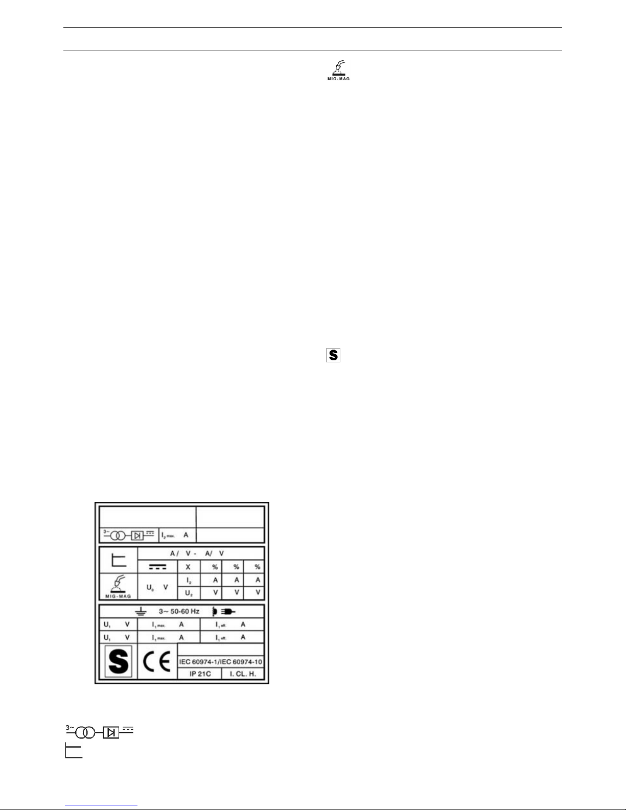
1.2 SPIEGAZIONE DEI DATI TECNICI
Fig. 1
IEC 60974-1 La saldatrice è costruita secondo queste
IEC 60974-10 norme.
Trasformatore-raddrizzatore trifase.
Caratteristica piatta.
Adatto per saldatura a filo continuo.
I2 max Corrente di saldatura non convenzionale.
Il valore rappresenta il limite max. ottenibile in
saldatura.
U0 Tensione a vuoto secondaria.
X Fattore di servizio percentuale.
Il fattore di servizio esprime la percentuale di
10 minuti in cui la saldatrice può lavorare ad
una determinata corrente senza causare
surriscaldamenti.
I2 Corrente di saldatura
U2 Tensione secondaria con corrente di sald. I2
U1 Tensione nominale di alimentazione.
3~ 50/60Hz Alimentazione trifase 50 oppure 60 Hz.
I1 max E' il massimo valore della corrente assorbita.
I1 eff E' il massimo valore della corrente effettiva
assorbita considerando il fattore di servizio.
IP21C Grado di protezione della carcassa.
Grado 1 come seconda cifra significa che
questo apparecchio non è idoneo a lavorare
all’esterno sotto la pioggia. La lettera
addizionale C significa che l'apparecchio è
protetto contro l'accesso di un utensile
(diametro 2,5 mm) alle parti in tensione del
circuito di alimentazione.
Idonea a lavorare in ambienti con rischio
accresciuto.
NOTE: La saldatrice è inoltre stata progettata per lavorare in
ambienti con grado di inquinamento 3. (Vedi IEC 60664).
1.3 PROTEZIONE TERMICA
Questo apparecchio è protetto da un termostato il quale, se
si superano le temperature ammesse, impedisce il
funzionamento della macchina. In queste condizioni, il
ventilatore continua a funzionare, il filo ad uscire e la
lampada C si accende.
2 INSTALLAZIONE
• L’installazione della macchina deve essere fatta da
personale qualificato.
• Tutti i collegamenti devono essere eseguiti in
conformità delle vigenti norme e nel pieno rispetto
della legge antinfortunistica.
Controllare che la tensione di alimentazione corrisponda al
valore indicato sul cavo rete. Se non è già montata, collegare
una spina di portata adeguata al cavo di alimentazione
assicurandosi che il conduttore giallo/verde sia collegato allo
spinotto di terra.
La portata dell'interruttore magnetotermico o dei fusibili, in
serie all'alimentazione, deve essere uguale alla corrente I
1
max. assorbita dalla macchina.
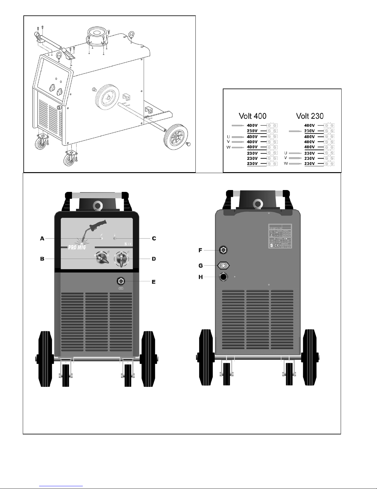
2.1 SISTEMAZIONE
Montare il manico, le ruote e il supporto carrello traina filo
(fig. 2). Il manico non deve essere usato per sollevare la
saldatrice.
Collocare la saldatrice in un ambiente ventilato.
Polvere, sporco o qualsiasi altra cosa estranea che possa
entrare nella saldatrice ne può compromettere la ventilazione
e quindi il buon funzionamento.
4
Pertanto è necessario in relazione all'ambiente e alle
condizioni di impiego avere cura di mantenere pulite le parti
interne. La pulizia deve avvenire tramite un getto di aria
secca e pulita, facendo attenzione a non danneggiare in
alcun modo la macchina. Prima di lavorare all'interno della
saldatrice assicurarsi che la spina sia staccata dalla rete di
alimentazione.
Qualsiasi intervento eseguito all'interno della saldatrice
deve essere eseguito da personale qualificato.
2.2 COLLEGAMENTI INTERNI
• Qualsiasi intervento eseguito all'interno della
saldatrice deve essere eseguito da personale
qualificato.
• Prima di lavorare all’interno della saldatrice assicurarsi
che la spina sia staccata dalla rete di alimentazione.
• Dopo il collaudo finale la saldatrice viene collegata
alla tensione indicata sul pannello vicino al cavo di
alimentazione.
• Per cambiare tensione di alimentazione togliete il
laterale destro e disponete i collegamenti della
morsettiera cambiatensione come indicato in fig. 3.
• Non utilizzare la saldatrice senza coperchio o i pannelli
laterali per evidenti ragioni di sicurezza e per non alterare
le condizioni di raffreddamento dei componenti interni.
2.3 COLLEGAMENTI ESTERNI
2.3.1 Connessione della pinza di massa
Connettere il terminale del cavo massa alla presa E della
saldatrice e collegare il morsetto di massa al pezzo da
saldare.
2.3.2 Posizionamento della bombola e collegamento del
tubo gas
• Posizionare la bombola sul porta bombola della saldatrice,
fissandola con le catene in dotazione, al pannello
posteriore della macchina.
• Controllare periodicamente lo stato di usura delle catene e,
se necessario, richiedere il ricambio.
• La bombola deve essere equipaggiata da un riduttore di
pressione comprensivo di flussometro.
• Solo dopo aver posizionato la bombola, collegare il tubo
gas uscente dal pannello posteriore della macchina al
riduttore di pressione.
• Regolare il flusso del gas a circa 10 -18 litri/minuto.
2.3.3 Connessione del carrello
Questo generatore funziona con i carrelli WF21 e WF41.
Le prestazioni e le possibilità operative dei carrelli sono
descritte nelle istruzioni allegate ai carrelli stessi.
3 DESCRIZIONE COMANDI
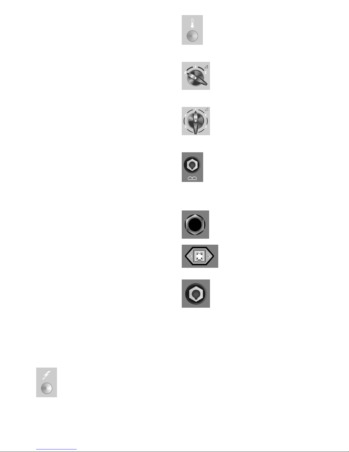
3.1 COMANDI SUL FRONTALE DELL’APPARECCHIO
(VEDERE FIG. 4)
A - Spia
Spia generale, acceso – spento.
C - Spia
Si accende quando il termostato interrompe il funzionamento
della saldatrice.
B – Interruttore / commutatore
Accende o spegne la macchina e seleziona le gamme della
tensione di saldatura.
D - Commutatore
Regola finemente la tensione di saldatura prescelta con il
commutatore B.
E - Presa di massa
Presa a cui va collegato il cavo massa.
3.2 COMANDI SUL PANNELLO POSTERIORE DEL
GENERATORE (VEDERE FIG. 4)
H - Presa di alimentazione
G - Connettore
A questo connettore va collegato il maschio della prolunga.
F - Presa
A questa presa va collegato il connettore volante di potenza
della prolunga (polo +).
4 SALDATURA
4.1 MESSA IN OPERA
Controllare che il diametro del filo corrisponda al diametro
indicato sul rullo trainafilo. Utilizzare rulli trainafilo con gola
ad “U” per fili di alluminio e con gola a “V” per gli altri fili.
4.2 LA MACCHINA È PRONTA PER SALDARE
• Connettere il morsetto di massa al pezzo da saldare.
• Posizionare l'interruttore B su 1 oppure su 2.
• Togliere l'ugello gas.
• Svitare l'ugello portacorrente.
• Inserire il filo nella guaina guidafilo della torcia
assicurandosi che sia dentro la gola del rullo e che

5
questo sia in posizione corretta.
• Premere il pulsante torcia per fare avanzare il filo fino alla
fuoriuscita dello stesso dalla torcia.
• Attenzione: tenere il viso lontano dalla lancia
terminale mentre il filo fuoriesce.
• Avvitare l'ugello portacorrente assicurandosi che il
diametro del foro sia pari al filo utilizzato.
• Montare l'ugello gas.
4.3 SALDATURA DEGLI ACCIAI AL CARBONIO CON
PROTEZIONE GASSOSA.
Per la saldatura di questi materiali è necessario:
• Utilizzare un gas di saldatura a composizione binaria, di
solito ARGON + CO2 con percentuali di Argon che vanno
dal 75% in su. Con questa miscela il cordone di saldatura
sarà ben raccordato ed estetico.
• Utilizzando CO2 puro, come gas di protezione si avranno
cordoni stretti, con una maggiore penetrazione ma con
un notevole aumento di proiezioni (spruzzi).
• Utilizzare un filo d'apporto della stessa qualità rispetto
all'acciaio da saldare. E' sempre bene usare fili di buona
qualità, evitare di saldare con fili arrugginiti che possono
dare difetti di saldatura.
• Evitare di saldare su pezzi arrugginiti o che presentano
macchie d'olio o grasso.
4.4 SALDATURA DEGLI ACCIAI INOSSIDABILI
La saldatura degli acciai inossidabili della serie 300, deve
essere eseguita con gas di protezione ad alto tenore di
Argon, con una piccola percentuale di ossigeno O2 o di
anidride carbonica CO2 circa il 2%. Non toccare il filo con le
mani. E’ importante mantenere sempre la zona di saldatura
pulita per non inquinare il giunto da saldare.
4.5 SALDATURA DELL'ALLUMINIO
Per la saldatura dell'alluminio è necessario utilizzare:
• Argon puro come gas di protezione.
• Un filo di apporto di composizione adeguata al materiale
base da saldare.
• Utilizzare mole e spazzonatrici specifiche per l'alluminio
senza mai usarle per altri materiali.
5 DIFETTI IN SALDATURA
1. DIFETTO -Porosità (interne o esterne al cordone)
CAUSE - Filo difettoso (arrugginito superficialmente)
- Mancanza di protezione di gas dovuta a:
flusso di gas scarso
flussometro difettoso
riduttore brinato, per la mancanza di un
preriscaldatore del gas di protezione di CO2
elettrovalvola difettosa
ugello porta corrente intasato da spruzzi
fori di efflusso del gas intasati
correnti d'aria presenti in zona di saldatura.
2. DIFETTO - Cricche di ritiro
CAUSE - Filo o pezzo in lavorazione sporchi od
arrugginiti.
- Cordone troppo piccolo.
- Cordone troppo concavo.
- Cordone troppo penetrato.
3. DIFETTO - Incisioni laterali
CAUSE - Passata troppo veloce
- Corrente bassa e tensioni di arco elevate.
4. DIFETTO - Spruzzi eccessivi
CAUSE - Tensione troppo alta.
- Induttanza insufficiente.
- Mancanza di un preriscaldatore del gas di
protezione di CO2
6 MANUTENZIONE DELL'IMPIANTO
• Ugello protezione gas
Questo ugello deve essere liberato periodicamente dagli
spruzzi metallici. Se distorto o ovalizzato sostituirlo.
• Ugello porta corrente.
Soltanto un buon contatto tra questo ugello ed il filo assicura
un arco stabile e un'ottima erogazione di corrente; occorre
perciò osservare i seguenti accorgimenti:
A) Il foro dell'ugello portacorrente deve essere tenuto esente
da sporco od ossidazione.
B) A seguito di lunghe saldature gli spruzzi si attaccano più
facilmente ostacolando l'uscita del filo.
E' quindi necessario pulire spesso l'ugello e se necessario
sostituirlo.
C) L'ugello porta corrente deve essere sempre ben avvitato
sul corpo torcia. I cicli termici subiti dalla torcia ne possono
creare un allentamento con conseguente riscaldamento del
corpo torcia e dell'ugello ed un’incostanza dell'avanzamento
del filo.
• Guaina guidafilo.
E' una parte importante che deve essere controllata spesso,
poiché il filo può depositarvi polvere di rame o sottilissimi
trucioli. Pulirla periodicamente assieme ai passaggi del gas,
con aria compressa secca.
Le guaine sono sottoposte ad un continuo logorio, perciò si
rende necessario, dopo un certo periodo, la loro sostituzione.
• Gruppo motoriduttore.
Pulire periodicamente l'insieme dei rulli di trascinamento da
eventuale ruggine o residui metallici dovuti al traino delle
bobine. E' necessario un controllo periodico di tutto il gruppo
responsabile del traino del filo: aspo, rullini guidafilo, guaina
e ugello porta corrente.

6
INSTRUCTION MANUAL FOR WIRE WELDING MACHINE
IMPORTANT
READ THIS MANUAL AND THE SAFETY RULES
MANUAL CAREFULLY BEFORE INSTALLING, USING,
OR SERVICING THE WELDING MACHINE, PAYING
SPECIAL ATTENTION TO SAFETY RULES. CONTACT
YOUR DISTRIBUTOR IF YOU DO NOT FULLY
UNDERSTAND THESE INSTRUCTIONS.
This machine must be used for welding only. It must not
be used to defrost pipes.
It is also essential to pay special attention to the "SAFETY
RULES" Manual. The symbols next to certain paragraphs
indicate points requiring extra attention, practical advice or
simple information.
This MANUAL and the "SAFETY RULES" MANUAL must
be stored carefully in a pica familiar to everyone involved
in using the machine. They must be consulted whenever
doubts arise and be kept for the entire lifespan of the
machine; they will also be used for ordering replacement
parts.
1 GENERAL DESCRIPTION
1.1 SPECIFICATIONS
This manual has been prepared for the purpose of
educating personnel assigned to install, operate and
service the welding machine.
This equipment is a constant-voltage power source,
suitable for MIG/MAG and OPEN-ARC welding.
Upon receiving the machine, make sure there are no
broken or damaged parts.
The purchaser should address any complaints for losses
or damage to the vector. Please indicate the article and
serial number whenever requesting information about the
welding machine.
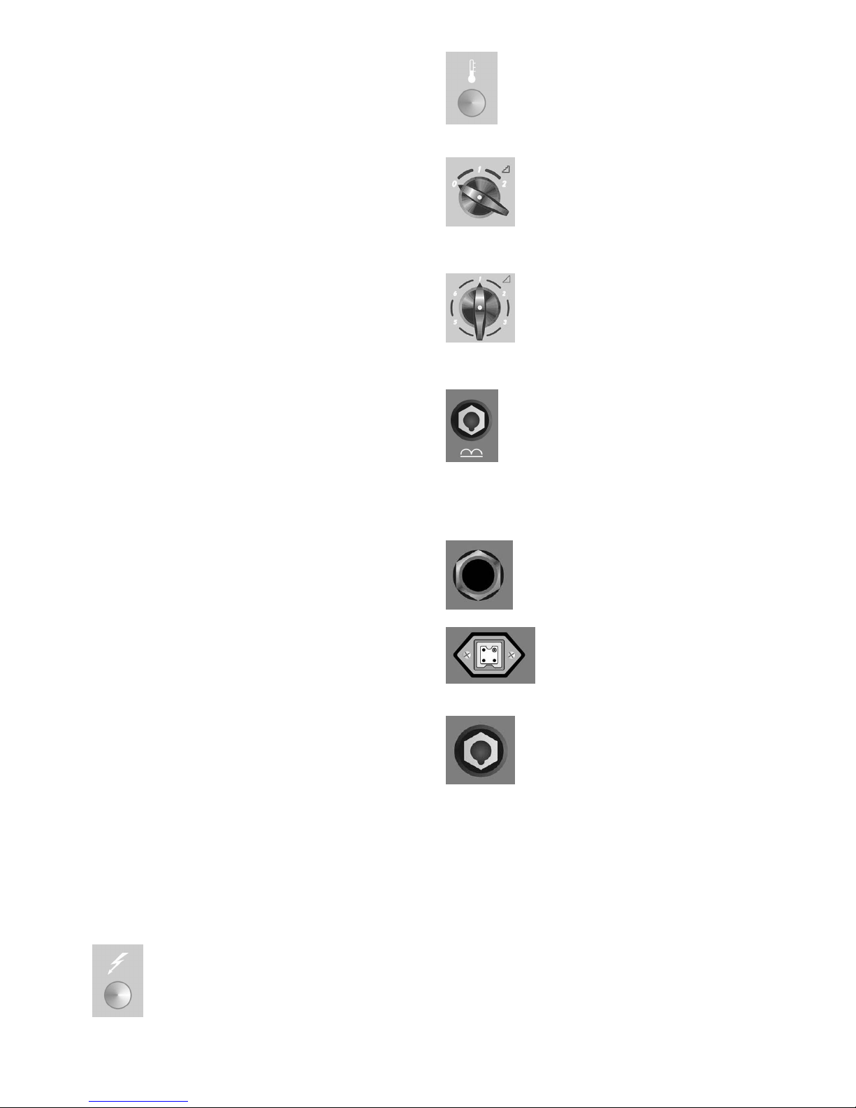
1.2 EXPLANATION OF TECHNICAL SPECIFICATIONS
Pict. 1
IEC 60974-1 The welding machine is manufactured
IEC 60974-10 according to these international
standards.
Three-phase transformer-rectifier.
Flat characteristic.
Suitable for continuous wire welding.
I2 max Unconventional welding current.
This value represents the max. limit
attainable in welding.
U0 Secondary open-circuit voltage.
X Duty cycle percentage.
The duty cycle expresses the percentage of
10 minutes during which the welding
machine may run at a certain current without
overheating.
I2 Welding current
U2 Secondary voltage with welding current I2.
U1 Rated supply voltage
3~ 50/60Hz 50- or 60-Hz three-phase power supply.
I1 max Maximum absorbed current value.
I1 eff This is the maximum value of the actual
current absorbed, considering the duty cycle.
IP21C Protection rating for the housing.
Grade 1 as the second digit means that this
equipment is suitable for use outdoors in the
rain. The additional letter C means that the
equipment is protected against access to the
live parts of the power supply circuit by a tool
(diameter 2.5 mm).
Suitable for use in high-risk environments.
NOTES: The welding machine has also been designed for
use in environments with a pollution rating of 3. (See IEC
60664).
1.3 OVERLOAD CUT-OUT
This machine is protected by a thermostat, which prevents
the machine from operating if the allowable temperatures
are exceeded. In these conditions, the fan continues to
operate, the wire to flow and the led C lights.
2 INSTALLATION
• Only skilled personnel should install the machine.
• All connections must be carried out according to
current regulations, and in full observance of safety
laws.
Make sure that the supply voltage corresponds to the
value indicated on the power cable. If it is not already
fitted, connect a plug suited to the power cable, making
sure that the yellow/green conductor is connected to the
earth pin.
The capacity of the overload cutout switch or fuses
installed in series with the power supply must be
equivalent to the absorbed current I1 max. of the machine.
2.1 PLACEMENT
Mount the handle, wheels and the wire feeder unit support
(pict. 2).
The handle must not be used for lifting the welding
machine.
Place the welding machine in a ventilated area.
Dust, dirt, and any other foreign matter entering the
welding machine can interfere with ventilation and thus
with smooth operation.
Therefore, in relation to the environment and working
conditions, it is important to keep the internal parts clean.
7
Clean using a jet of dry, clean air, being careful to avoid
damaging the machine in any way.
Before working inside the welding machine, make sure it is
unplugged from the power mains.
Any intervention carried out inside the welding
machine must be performed by qualified personnel.
2.2 INTERNAL CONNECTIONS
• Any intervention carried out inside the welding
machine must be performed by qualified personnel.
• Before working inside the welding machine, make sure
that the plug is disconnected from the power mains.
• After final inspection, the welding machine is
connected to the voltage indicated on the panel
beside the power supply cable.
• To change the supply voltage, remove the right side
panel and arrange the voltage change terminal
board connections as shown in the picture 3.
• The supply voltage may not be changed on single-
phase power sources.
• Do not use the welding machine without its cover or side
panels for obvious safety reasons, and to avoid altering
the cooling conditions for internal components.
2.3 EXTERNAL CONNECTIONS
2.3.1 Connecting the mass clip
Connect the earth cable terminal to the socket E of the
welding machine, and connect the earth clamp to the
workpiece.
2.3.2 Cylinder placement and connecting the gas hose
• Position the cylinder on the cylinder holder of the
welding machine, using the chains provided to fasten it
to the rear panel of the machine.
• Periodically check for wear of chains and order
replacements if necessary.
• The cylinder must be equipped with a pressure regulator
complete with flow gauge.
• Only after positioning the cylinder, connect the outgoing
gas hose from the rear panel of the machine to the
pressure regulator.
• Adjust the gas flow to approximately 10/18 liters/minute.
2.3.3 Connecting the wire feeder
This power source works with the wire feeders WF21 and
WF41. The performance and operating options of the wire
feeder are described in the instructions enclosed with the
wire feeder itself.
3 DESCRIPTION OF CONTROLS
3.1 CONTROLS ON THE FRONT OF THE MACHINE
(see pict. 4)
A - Light
Main ON/OFF indicator lamp.
C – Light
Thermostat pilot light.
B - Switch
Turns the machine ON or OFF and select the ranges of
welding voltage.
D – Switch
Fine-tunes the welding voltage within the range previously
selected via selector switch B.
E- Earth socket
Socket to which to connect the earth cable.
3.2 CONTROLS ON GENERATOR REAR PANEL (see
pict. 4)
H – Input supply socket
G - Socket connector.
For the male connector on extension lead.
F - Socket.
For the extension lead power supply connector (‘+’ pole).
4 WELDING
4.1 INSTALLATION
Make sure that the wire diameter corresponds to the
diameter indicated on the wire feeder roller. Use wire
feeder rollers with a "U"-shaped groove for aluminium
wires, and with a "V"-shaped groove for other wires.
4.2 THE MACHINE IS READY TO WELD
• Connect the earth clamp to the workpiece.
• Set the switch B to 1 or 2 position.
• Remove the gas nozzle.

8
• Unscrew the contact tip.
• Insert the wire in the wire liner of the torch, making sure
that it is inside the roller groove and that the roller is in
the correct position.
• Press the torch trigger to move the wire forward until it
comes out of the torch.
• Caution: keep your face away from the gun tube
assembly while the wire is coming out.
• Screw the contact tip back on, making sure that the hole
diameter is the same as that of the wire used.
• Assemble the gas nozzle.
4.3 WELDING CARBON STEELS WITH GAS
PROTECTION.
In order to weld these materials you must:
• Use a welding gas with a binary composition, usually
ARGON + CO2 with percentages of Argon ranging from
75% up. With this blend, the welding bead will be well
jointed and attractive.
• Using pure CO2 as a protection gas will produce narrow
beads, with greater penetration but a considerably
increase in splatters.
• Use a welding wire of the same quality as the steel to be
welded. It is best to always use good quality wires,
avoiding welding with rusted wires that could cause
welding defects.
• Avoid welding rusted parts, or those with oil or grease
stains.
4.4 WELDING STAINLESS STEEL
Series 300 stainless steels must be welded using a
protection gas with a high Argon content, containing a
small percentage of O2 or carbon dioxide CO2
(approximately 2%) to stabilize the arc.
Do not touch the wire with your hands. It is important to
keep the welding area clean at all times, to avoid
contaminating the joint to be welded.
4.5 WELDING ALUMINIUM
In order to weld aluminium you must use:
• Pure Argon as the protection gas.
• A welding wire with a composition suitable for the base
material to be welded.
• Use mills and brushing machines specifically designed
for aluminium, and never use them for other materials.
5 WELDING DEFECTS
1. DEFECT- - Porosity (within or outside the bead)
CAUSES - Electrode defective (rusted surface)
- Missing shielding gas due to:
low gas flow
flow gauge defective
regulator frosted due to no preheating of the
CO2 protection gas
defective solenoid valve
contact tip clogged with spatter
gas outlet holes clogged
air drafts in welding area.
2. DEFECT - Shrinkage cracks
CAUSES - Wire or workpiece dirty or rusted.
- Bead too small.
- Bead too concave.
- Bead too deeply penetrated.
3. DEFECT - Side cuts
CAUSES - Welding pass done too quickly
- Low current and high arc voltages.
4. DEFECT - Excessive spraying
CAUSES - Voltage too high.
- Insufficient inductance.
- No preheating of the CO2 protection gas
6 MAINTAINING THE SYSTEM
• Shielding gas nozzle
This nozzle must be periodically cleaned to remove weld
spatter. Replace if distorted or squashed.
• Contact tip.
Only a good contact between this contact tip and the wire
can ensure a stable arc and optimum current output; you
must therefore observe the following precautions:
A) The contact tip hole must be kept free of grime and
oxidation (rust).
B) Weld spatter sticks more easily after long welding
sessions, blocking the wire flow.
The tip must therefore be cleaned more often, and
replaced if necessary.
C) The contact tip must always be firmly screwed onto the
torch body. The thermal cycles to which the torch is
subjected can cause it to loosen, thus heating the torch
body and tip and causing the wire to advance unevenly.
• Wire liner.
This is an important part that must be checked often,
because the wire may deposit copper dust or tiny
shavings. Clean it periodically along with the gas lines,
using dry compressed air.
The liners are subjected to constant wear and tear, and
therefore must be replaced after a certain amount of time.
• Gearmotor group.
Periodically clean the set of feeder rollers, to remove any
rust or metal residue left by the coils. You must
periodically check the entire wire feeder group: hasp, wire
guide rollers, liner and contact tip.
 Loading...