

Elettro CF MMA 793, MMA 795, MMA 796, MMA 794, MMA 797 Instruction Manual
...
I MANUALE D'ISTRUZIONI PER SALDATRICI AD ARCO .........................................Pag. 2
GB INSTRUCTION MANUAL FOR ARC WELDING MACHINES ....................................Pag. 5
D BEDIENUNGSANLEITUNG FÜR STABELEKTRODEN-SCHWEISSMASCHINEN..... Pag. 8
F MANUEL D'INSTRUCTIONS POUR POSTES A SOUDER A L'ARC.......................... Pag. 11
E MANUAL DE INSTRUCCIONES PARA SOLDADORAS DE ARCO ........................... Pag. 14
P MANUAL DE INSTRUÇÕES PARA SOLDADORES COM ARCO .............................. Pag. 17
Parti di ricambio e schema elettrico
Spare parts and wiring diagram
Ersatzteile und elektrischer Schaltplan
Pièces de rechanges et schéma électrique
Partes de repuesto y esquema eléctrico
Peças e esquema eléctrico ......................................................................................................... Pagg. Seiten .....................20
MANUALE DI ISTRUZIONI PER SALDATRICI AD ARCO
U2.................... Tensione secondaria con corrente di
saldatura I2.
1 DESCRIZIONI GENERALI
U
1
.................... Tensione nominale di alimentazione.
Prima dell’installazione, dell’uso o di qualsiasi
manutenzione alle macchine, leggere attentamente il
contenuto del libretto “Regole di sicurezza per l’uso
delle apparecchiature” e del “Manuale di istruzioni”
specifico per ogni macchina. Contattate il vostro
distributore se non avete compreso completamente le
istruzioni.
3~50(60)Hz....... Alimentazione trifase 50 oppure 60Hz.
I
1
..................... Corrente assorbita alla corrispondente
corrente di saldatura I2.
IP 21................ Gradi di protezione della carcassa. Grado
1 come seconda cifra significa che questo
apparecchio non é idoneo a lavorare
all'esterno sotto alla pioggia.
Questo manuale è stato preparato allo scopo di istruire il
personale addetto all'installazione, al funzionamento ed alla
manutenzione della saldatrice.
................ Idonea a lavorare in ambienti con rischio
accresciuto.
Questo apparecchio è un generatore di corrente continua
costante adatto alla saldatura di elettrodi rivestiti e con
procedimento TIG con accensione a contatto.
NOTE: La saldatrice è inoltre stata progettata per lavorare in
ambienti con grado di polluzione 3 (Vedi IEC 664).
Controllare, al ricevimento della saldatrice, che non vi siano
parti rotte o avariate. Ogni eventuale reclamo per perdite o
danni deve essere fatto dall'acquirente al vettore.
2 INSTALLAZIONE
2.1 SISTEMAZIONE
Ogni qualvolta si richiedono informazioni riguardanti la
saldatrice, si prega di indicare l'articolo ed il numero di
matricola.
Tutti i collegamenti devono essere eseguiti in conformità alle
vigenti norme e nel pieno rispetto della legge
antinfortunistica (Vedi norma CEI 26-10 CENELEC HD427).
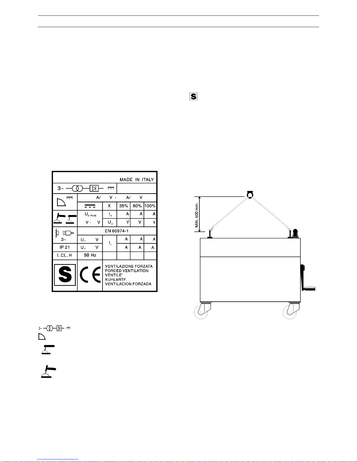
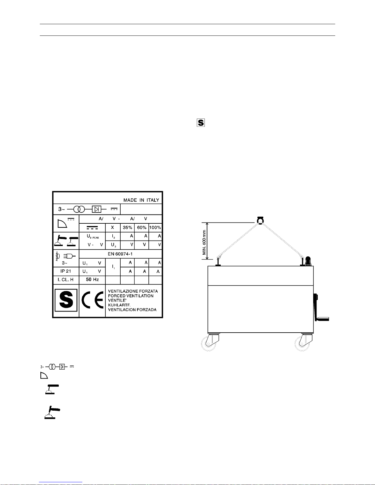
1.1 SPIEGAZIONE DEI DATI TECNICI
Montare i particolari in corredo alla saldatrice.
Per il sollevamento della macchina, utilizzare le due golfare
superiori disponendo le funi come indicato in figura: il
manico NON deve essere utilizzato per il sollevamento.
IEC 974.1.......... La saldatrice è costruita secondo
EN 60974.1 queste norme internazionali.
N°.................... Numero di matricola. Da citare sempre
per qualsiasi richiesta relativa alla
saldatrice.
2.2 COLLEGAMENTI PRIMARI
.... Trasformatore - raddrizzatore trifase.
................... Caratteristica discendente.
• Collegare il conduttore giallo verde della saldatrice ad
una buona presa di terra.
........... Adatto per saldatura per elettrodi
rivestiti.
• Non usare come conduttori di terra le tubazioni
dell'acqua.
• Dopo il collaudo finale la saldatrice é collegata alla
tensione di alimentazione massima indicata sul
pannello anteriore.
........... Adatto per saldatura TIG.
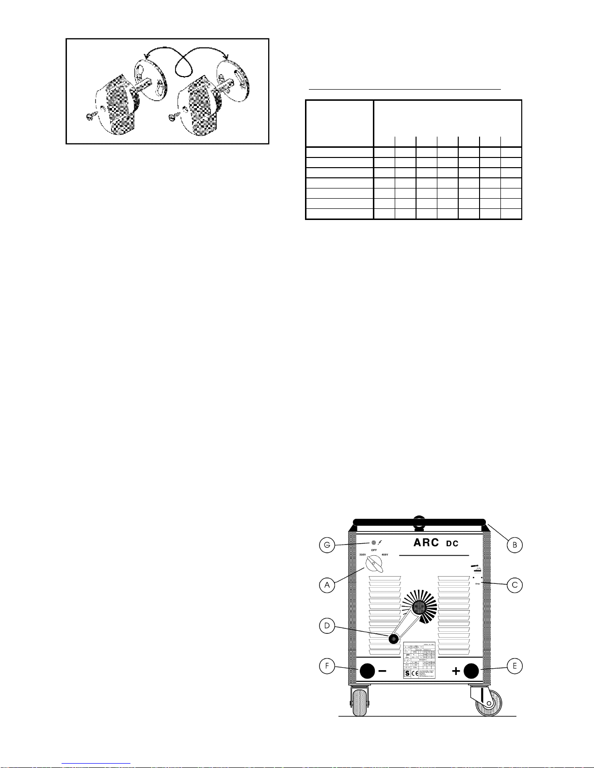
• Se si desidera cambiare tensione di alimentazione:
U
0 PEAK
................ Tensione a vuoto secondaria. Valore di
picco.
− Posizionare il commutatore in posizione zero (macchina
spenta).
X..................... Fattore di servizio percentuale. Il
fattore di servizio esprime la
percentuale di 10 minuti in cui la
saldatrice può lavorare ad una
determinata corrente senza causare
surriscaldamenti.
− Sfilare la manopola del commutatore svitando la vite di
bloccaggio; si presenta il dischetto cambiatensione.
− Posizionare il dischetto in maniera tale che il
commutatore possa girare solo verso la tensione desiderata
indicata sul pannello.
− Infilare la manopola e bloccarla con la vite.
I
2.
.................... Corrente di saldatura.
2
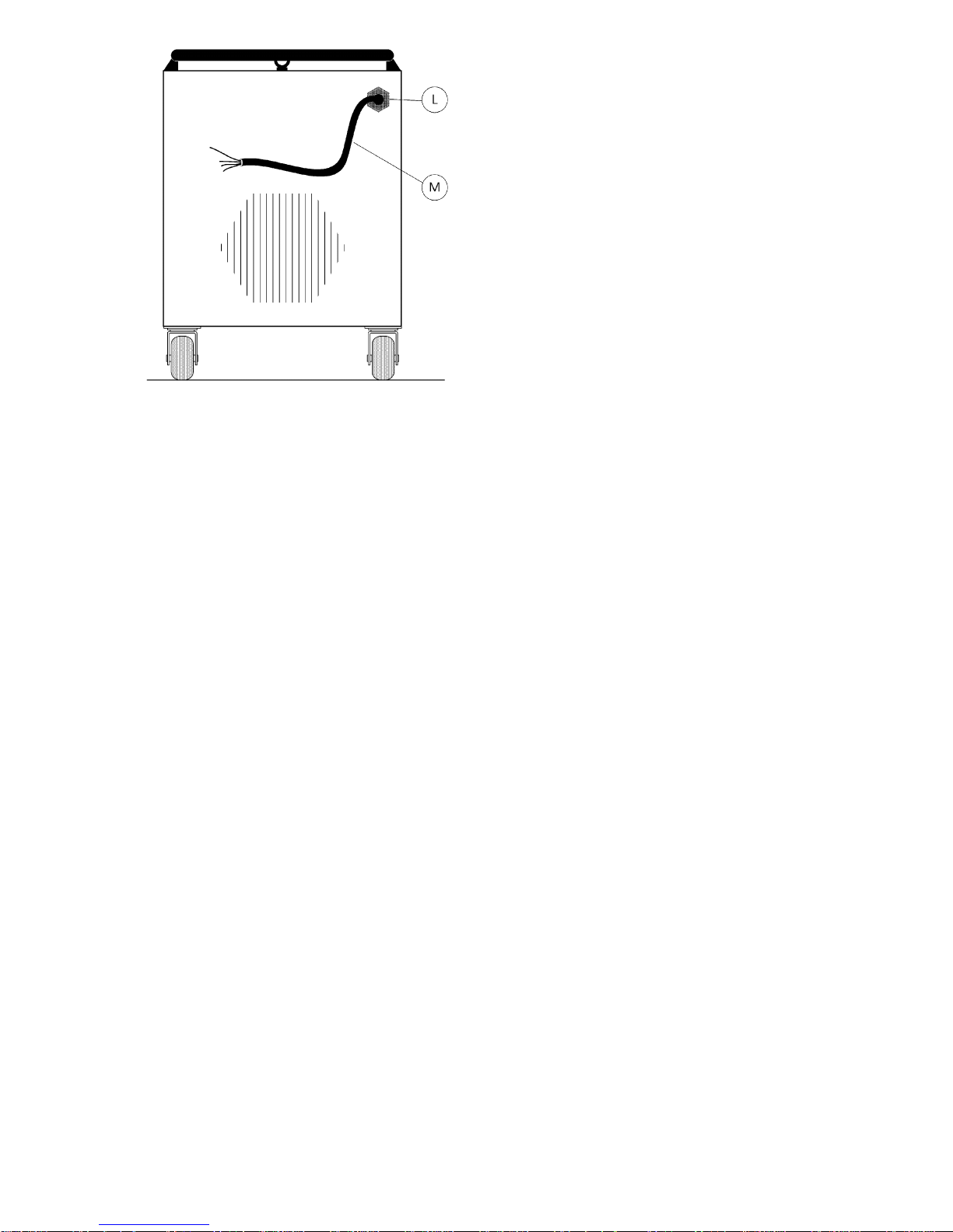
Collegare il cavo di alimentazione: il conduttore giallo verde
del cavo deve essere collegato ad un'efficiente presa di
terra dell'impianto; i rimanenti conduttori devono essere
collegati alla linea di alimentazione attraverso un interruttore
posto, possibilmente vicino alla zona di saldatura per
permettere uno spegnimento veloce in caso di emergenza.
La portata dell'interruttore magnetotermico o dei fusibili in
serie all'interruttore deve essere uguale o superiore alla
corrente I
1
assorbita dalla macchina.
3
La corrente I
1
assorbita si deduce dalla lettura dei dati
tecnici riportati sulla macchina in corrispondenza della
tensione di alimentazione U
1
a disposizione.
Eventuali prolunghe debbono essere di sezione adeguata
alla corrente I
1
assorbita.
2.3 COLLEGAMENTI SECONDARI
2.3.1 Collegamento della pinza porta elettrodo
• La pinza portaelettrodo dovrà essere connessa alla
macchina in modo da rispettare la polarità indicata sulla
scatola degli elettrodi che andrete ad usare. Quando
collegate il cavo della pinza portaelettrodo e il cavo di
massa siate sicuri che i terminali di potenza dei cavi siano
ben stretti.
• Le ganasce della pinza portaelettrodo debbono essere
mantenute strette e le superfici in buone condizioni per
consentire un buon contatto con la vergella degli elettrodi.
• Ganasce difettose permetterebbero agli elettrodi di
muoversi rendendo difficoltosa la saldatura.
• La connessione tra il cavo e la pinza portaelettrodo deve
sempre essere mantenuta serrata.
• Usate pinze portaelettrodo ben isolate.
• Non toccate mai contemporaneamente le pinze di due
saldatrici diverse.
• Evitate sempre contatti tra parti del corpo e la pinza
portaelettrodo o l'elettrodo.
2.3.2 Collegamento del morsetto di massa
• Siate sicuri che il morsetto di massa faccia un buon
contatto sul pezzo da saldare.
• Assicuratevi che il cavo sia ben serrato al morsetto di
massa, controllate periodicamente che queste connessioni
siano ben strette.
• Una giunzione non ben serrata può causare cali di
corrente in saldatura, riscaldamenti eccessivi del cavo e del
morsetto di massa con conseguente pericolo di bruciature
dovute a contatti accidentali.
• Il circuito di saldatura non deve essere posto
deliberatamente a contatto diretto o indiretto con il
conduttore di protezione se non nel pezzo da saldare.
• Se il pezzo in lavorazione viene collegato
deliberatamente a terra attraverso il conduttore di
protezione, il collegamento deve essere il più diretto
possibile ed eseguito con un conduttore di sezione almeno
uguale a quello del conduttore di ritorno della corrente di
saldatura e connesso al pezzo in lavorazione nello stesso
punto del conduttore di ritorno utilizzando un secondo
morsetto di massa posto immediatamente vicino.
2.3.3 Scelta appropriata dei cavi di saldatura
Si raccomanda di impiegare cavi di saldatura tipo H01 N2-D
oppure tipo H01 N2-E conformi a CENELEC HD22.6 SI, i
più corti possibile.
Una eccessiva resistenza dei cavi di saldatura può ridurre la
corrente erogabile in saldatura.
Le prestazioni di qualsiasi saldatrice ad arco dipendono, in
gran parte, dallo stato dei cavi e dalle loro connessioni.
SEZIONE DEI CAVI DI SALDATURA IN mm
2
CORRENTE DI
SALDATURA
IN AMPERE
DISTANZA IN METRI DALLA SALDATRIC
E
15 20 30 40 45 50 60
100
35 35 35 50 50 50 50
150
35 35 50 50 70 70 90
200
35 50 50 70 70 95 100
250
35 50 70 70 95 100 150
300
50 70 70 95 100 150 150
350
50 70 95 100 150 150 200
400
50 95 95 150 150 200 210
N.B. Le sezioni in mm2 della tabella sono intese per ogni
singolo conduttore (Pinza o Massa).
Le sezioni dei cavi si possono ottenere collegando in
parallelo 2 o 3 conduttori della stessa sezione ad esempio:
150 mm2 = 3 conduttori in parallelo di 50 mm2
200 mm2 = 2x95 mm2 oppure 3x70 mm2
2.3.4 Collegamenti per il parallelo delle saldatrici
Due saldatrici possono essere collegate in parallelo in modo
da ottenere una corrente di saldatura superiore a quella
erogata da ogni singolo generatore.
E' importante che il polo positivo di una macchina sia
collegato al polo positivo dell'altra macchina come pure il
polo negativo della prima macchina deve essere collegato al
polo negativo della seconda macchina.
Per questi collegamenti è importante rispettare le sezioni
indicate in tabella.
Disporre poi l'indice di regolazione della corrente in modo
che ciascuna macchina eroghi metà della corrente richiesta
al fine di equilibrare i riscaldamenti e di conseguenza
utilizzare in modo ottimale il fattore di servizio disponibile
dalle due macchine.
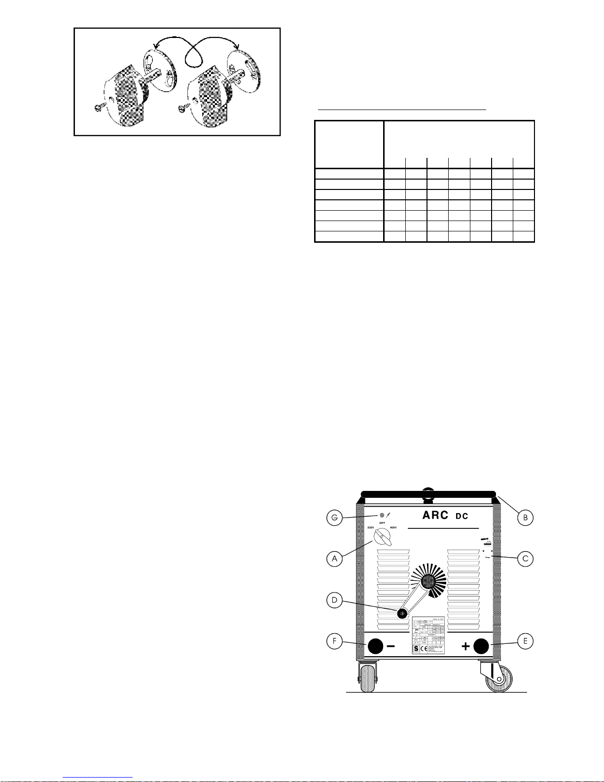
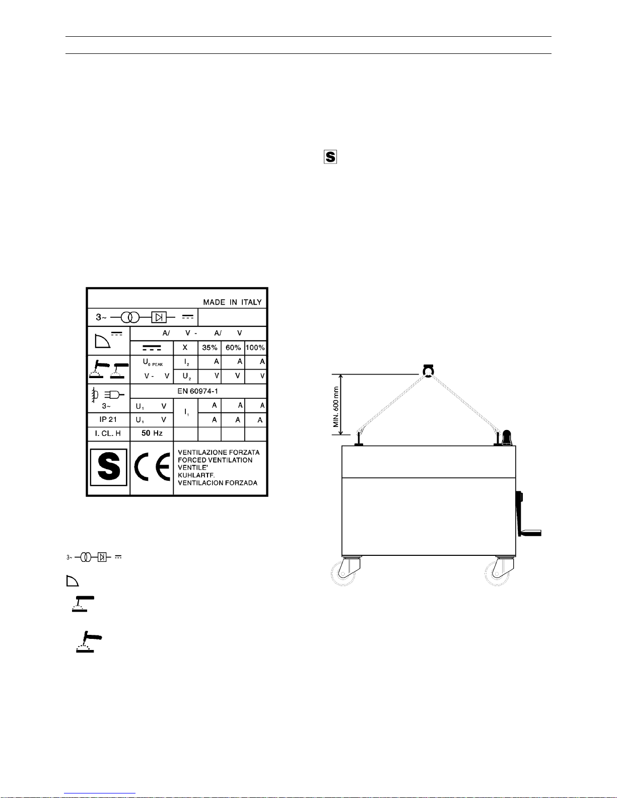
3 DESCRIZIONE DEI COMANDI SUL PANNELLO
4 MANUTENZIONE
ATTENZIONE : Qualsiasi operazione deve essere eseguita
da personale qualificato.
Spegnete la saldatrice e scollegate la spina prima di operare
all'interno della macchina.
Mantenere i cavi di saldatura, la pinza porta elettrodo ed il
morsetto di massa in buone condizioni.
Periodicamente pulire la macchina internamente. Soffiare
via la polvere accumulata con un getto moderato di aria
secca.
5 ANOMALIE DI FUNZIONAMENTO
• La macchina non si accende :
→ Spina di alimentazione non collegata.
→ Manca una fase di alimentazione.
• La macchina si accende ma non eroga corrente :
→ Accessori per saldatura non collegati.
→ Macchina non collegata alla giusta tensione di
alimentazione.
• Bruciano i fusibili di linea :
A) Commutatore principale:
→ Potenza di installazione non sufficiente.
Accende o spegne la macchina. Sotto la manopola è
situato il cambiatensione.
→ Macchina non collegata alla giusta tensione di
alimentazione.
B) Manico completo.
→ Trasformatore di potenza in corto circuito.
C) Indice di regolazione:
→ Raddrizzatore in corto circuito
Indica la corrente di saldatura a cui è regolata la
macchina.
• Corrente di saldatura instabile o non corretta :
→ Collegamenti primari e/o secondari non corretti.
D) Manovella di regolazione della corrente di
saldatura:
→ Elettrodo inadeguato.
→ Cavi di saldatura non serrati ai morsetti o falsi
contatti nelle giunzioni.
Girando questa manovella in senso orario si aumenta
l'intensità della corrente, in senso antiorario la si
diminuisce.
→ Macchina non collegata alla giusta tensione di
alimentazione.
E) Polo positivo.
• Il ventilatore non gira ma la corrente di saldatura é
corretta :
F) Polo negativo.
G) Lampada spia :
→ Motore del ventilatore difettoso.
Segnala che la macchina è in funzione.
→ Cavi di alimentazione del motore interrotti.
Prima dell'uso di questa saldatrice leggere attentamente le
norme CEI 26/9 oppure CENELEC HD407 e CEI 26/11
oppure CENELEC HD 433 inoltre verificare l'integrità
dell'isolamento dei cavi. A lavoro terminato ricordarsi di
spegnere la saldatrice.
→ Fusibile di protezione del moto-ventilatore
bruciato.
4
INSTRUCTION MANUAL FOR STICK WELDING MACHINE
1 GENERAL INFORMATION
Before using this device all people authorised to its
use, repair or inspection, should read the book
“Safety rules for using machines” and the
“Instruction manual” specific for every machine.
Contact your distributor if you have not understood
some instructions.
This manual has been prepared with the intent of
instructing the operator on how to install, operate, and
properly maintain this electric arc welding machine.
This welding machine must be used only with the
purposes described in the instruction manual. Upon
receiving and unpacking the machine, make a careful
inspection to ensure that there are no damaged parts.
Should there be a claim for losses or damages it must be
made by the purchaser directly to the shipper who handled
the goods.
When requesting information about this welding
machine, please state the machine part number and
serial number to ensure receiving accurate
information relating to your machine.
1.1 DESCRIPTION OF TECHNICAL SPECIFICATIONS
IEC 974.1.......... This machine is manufactured
EN 60974.1 according to these international
standards.
N°.................... Machine Serial Number which must
appear on requests or enquiries
relating to the machine.
.... Three phase transformer rectifier
................... Drooping characteristic.
........... Shielded Metal Arc Welding (Stick
Welding).
........... Suitable for TIG welding.
U
0 PEAK
................ Secondary no-load voltage. Peak
value.
X..................... Duty-Cycle Percentage.
The duty cycle is the number of
minutes, expressed as a percentage,
the machine can operate (arc on )
within a ten minute period without
overheating.
I2..................... Output welding current.
U2.................... Secondary voltage, welding current=I2.
U1.................... Nominal supply voltage.
3~50(60)Hz....... Three phase input supply at 50 or 60 Hz.
I1..................... Input Amps absorbed corresponding to
different output levels I2.
IP 21................ Machine case protection class. The 1 in
the singles digit place means that this unit
is no fit to work outdoors in the rain.
................ Fit to work in hazardous areas.
NOTE: This machine has also been designed to work in
class 3 pollution areas (see IEC 664).
2 INSTALLATION
2.1 SET-UP
All connections must be made in compliance with current
regulations and in full respect of safety laws (see CENELEC
HD 427 standard).
Assemble the parts supplied with the welding machine.
To lift the machine use the two upper eyebolts, placing the
ropes as shown in fig.1.
The handle must NOT be used for lifting.
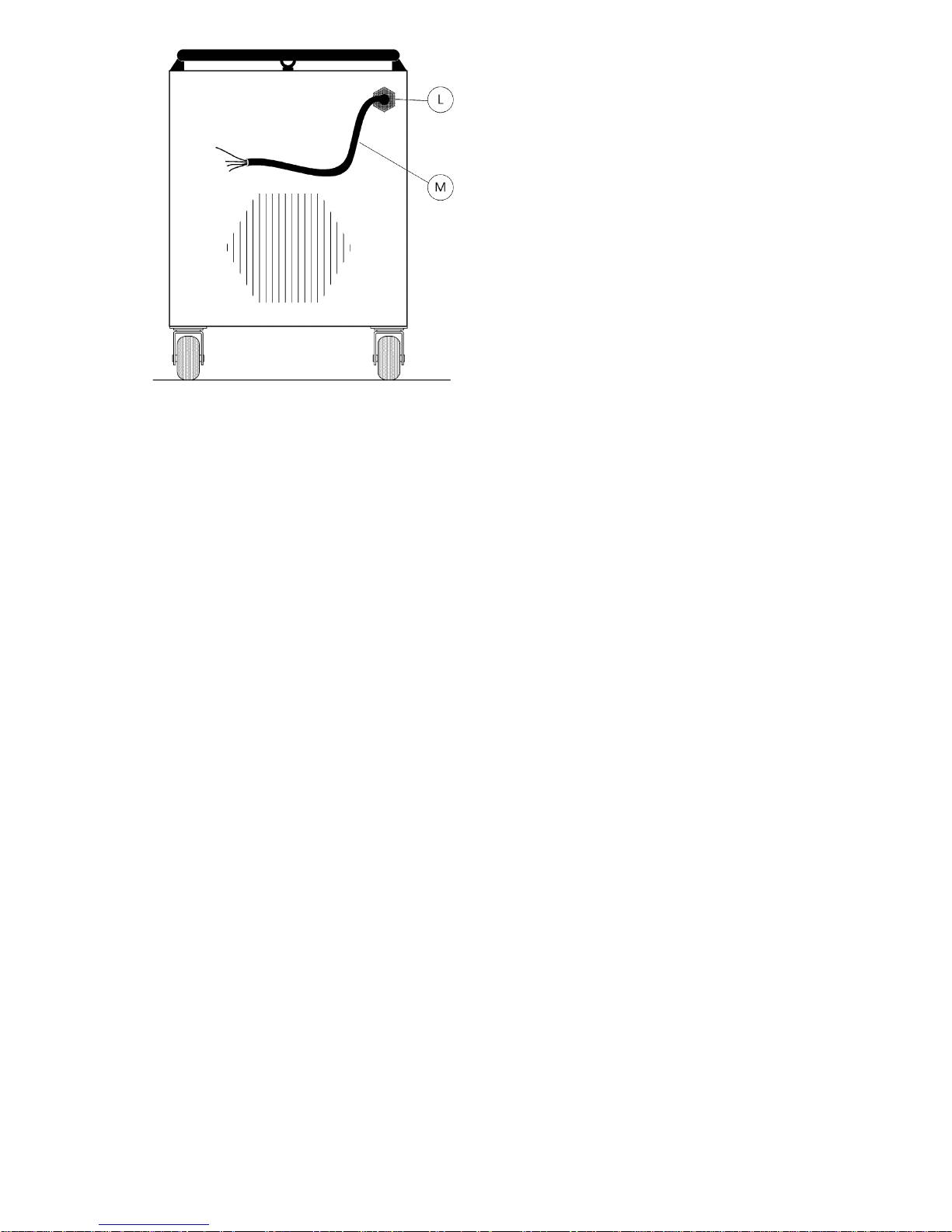
2.2 CONNECTIONS
• Connect the yellow-green wire to a good electrical
ground.
• Never use water pipes as ground conductors.
• After final inspection, the welding machine should be
connected to the maximum power supply voltage
indicated on the front panel.
If you wish to change the power supply voltage:
− Set the selector switch knob to the zero position
(machine off).
− Remove the selector switch knob by unscrewing the
holding screw; beneath you will find the voltage change disk
− Position it so that the selector switch may turn only
towards the desired voltage indicated on the panel
− Insert the knob and fasten it in place with the screw .
5
Connect supply cable : the yellow-green wire of cable
must be connected to an efficient earth point of the
system, the remaining wires should be connected to the
feed line through an isolation switch placed, if possible,
close to the working area so as to switch the unit off
quickly if necessary.
6
The magnetothermic switch capacity or of fuses in series
with switch should be equal or above the current I
1
absorbed is known by reading the technical specifications
on the unit i.e. feed voltage U
1
available.
Any extensions should have adequate sections for current
absorbed I
1
.
2.3 OUTPUT CONNECTIONS
2.3.1 Connecting the electrode holder
• The electrode holder must be connected to the machine
in compliance with the polarity indicated on the box of
electrodes that you are going to use.
• When you connect the electrode holder cable and the
hearth cable, make sure that the power cable terminals
are well tightened.
• T he jaws of the electrode holder must be kept tightened
and the surfaces must be kept in good condition to ensure
good contact with the electrode rod.
• Defective jaws will allow the electrodes to move which
will make welding difficult.
• The connection between the electrode holder cable and
the electrode holder must be well tightened.
• Use well insulated electrode holders.
• Never touch the electrode holders of two different
welding machines at the same time.
• Always avoid contact between parts of the body and the
electrode holder and/or the electrode.
2.3.2 Connecting the Earth Clamp
• Make sure that the earth clamp makes good contact
with the workpiece.
• Check that the earth cable is tightly fitted to earth clamp;
periodically check to make sure that this connection
remains well tightened.
A poorly tightened connection can cause current drops
during welding and also cause overheating of the earth
clamp and cable which can create the danger of burns.
• The weld circuit must not be purposefully placed in
direct or indirect contact with the protection lead if not in
the workpiece.
• If the workpiece is intentionally connected to the system
earth by means of a protection lead, the connection has to
be as direct as possible and done with a lead that has a
cross section at least equal to that of the welding current
return cable.
A second earth clamp, placed in the immediate vicinity,
can also be used.
2.3.3 Choosing the right welding cables
We recommend using the shortest possible welding
cables type H01 N2-D or H01 N2-E, in compliance with
CENELEC HD22.6 S1.
Too much resistance in the welding cables can reduce the
output available for the welding.
The performance of any arc welding machine depends,
generally, on the condition of the cables and the cable
connections.
CROSS SECTIONS OF WELDING CABLES IN mm
2
WELDING
CURRENT IN
AMPERE
DISTANCE IN METRES FROM THE
MACHINE
15 20 30 40 45 50 60
100
35 35 35 50 50 50 50
150
35 35 50 50 70 70 90
200
35 50 50 70 70 95 100
250
35 50 70 70 95 100 150
300
50 70 70 95 100 150 150
350
50 70 95 100 150 150 200
400
50 95 95 150 150 200 210
NOTE: The cross sections listed in the table are those for
each single conductor (electrode holder or ground clamp).
The cross sections listed in the table are those for each
single conductor (electrode holder or group clamp).
The cross sections of the cables can be obtained by
connecting in parallel 2 or 3 conductors having the same
cross section. For example :
150mm2=three 50mm2 cables linked together in parallel.
200mm2=2x95 mm2 cables or 3x70 mm2 cables linked
together in parallel.
2.3.4 Connecting two weldin g machines in parallel
Two welding machines can be connected in parallel so that
one obtains on output current greater than the output
current of each single machine.
It is important that the positive pole of one machine is
connected to the positive pole of the other machine and
likewise that the negative pole of one machine is connected
to the negative pole of the other machine.
When making this connections it is important to abide by the
cross sections shown in the table.
After having connected two machines in parallel, set the
output current of each machine to the halfway point so that
each machine will produce half of its maximum output
current.
This is recommended in order to balance the heath
produced by each machine, thus allowing the operator to
make the best use of duty cycles of both machines.
3 PANELS DESCRIPTION
A) Main selector switch:
Turns the machine on or off. The voltage change disk
is located beneath the knob.
B) Complete handle.
C) Setting indicator:
Indicates the welding current to which the machine is
set.
D) Welding current adjustment knob:
Turn this knob clockwise to increase the current
intensity, or counter-clockwise to decrease.
E) Positive terminal.
F) Negative terminal.
G) On-light:
Indicates that the machine is running.
Before using this welding machine, carefully read the
regulations CENELEC HD407 and CENELEC HD 433.
Also make sure that the insulation on cables, torch and
earth cable is intact.
Remember! Switch machine off when not in u se.
4 MAINTENANCE
WARNING: All servicing repair must be done by qualified
personnel.
Before opening the machine case to service or repair, turn
the machine off and disconnect the plug from the power
supply.
Keep the welding cables, the electrode holder, and the
earth clamp in good condition.
Periodically clean inside the machine blowing dust and dirt
away from internal components with a light jet of dry air.
5 TROUBLESHOOTING
• The machine does not turn on :
→ Input power cord no plugged in.
→ One power supply phase missing.
• The machine switches on but does not supply
current :
→ Welding accessories not connected.
→ Machine not connected to the right supply
voltage.
• The line fuse blow :
→ Installed line power insufficient.
→ Machine not connected to the right supply
voltage.
→ Power transformer in short circuit.
• Welding current unstable or incorrect :
→ Primary or secondary connections incorrectly
fitted.
→ Inadequate electrode.
→ Welding cables not properly tightened to the
output terminals or false contacts in connections.
→ Machine not connected to the right supply voltage.
• The fan does not work but the output welding
current is correct:
→ Defective fan motor.
→ Interruption in the leads that supply power to the
fan motor.
→ Fan motor fuse blown.
7
BEDIENUNGSANLEITUNG FÜR STABELEKTRODEN - SCHWEISSMASCHINE
1 ALLGEMEINES
U
1
.................... Versorgungsnennspannung.
3~50(60)Hz....... Dreiphasenversorgung 50 oder 60 Hz.
Lesen Sie bitte vor der Installation, Benützung oder
Wartung der Maschinen den Inhalt des Buches
“Sicherheitsvorschriften für die Benützung der
Maschinen” und des “Anleitungshandbuches”
spezifisch für jede Maschine mit Aufmerksamkeit.
Falls Sie fragen haben, wenden Sie sich bitte an Ihren
Fachhändler.
I
1
..................... Stromaufnahme bei entsprechendem
Schweißstrom I2.
IP 21................ Schutzart des Gehauses.
Schutzart 1 als zweite Zahl bedeutet, daß
dieses Gerät zur Arbeit bei Regen im Freien nicht geeignet
ist.
................ Zur Arbeit in Räumen mit erhöhter
elektrischer Gefährdung.
Dieses Handbuch dient zur Einweisung des InstallationsBedienungs - und Wartungspersonals der
Schweißmaschine. Diese Gerät ist ein
Gleichstromerzeuger zum Schweißen im WIG-Verfahren
mit Kontaktzündung. Beim Empfang der
Schweißmaschine prüfen Sie die Bestandteile auf Bruch
und Beschädigung. Eventuelle Reklamationen wegen
Verlust oder Beschädigung sind an das
Transportunternehmen zu richten.
ANMERKUNG: Die Schweißmaschine ist ferner für die
Arbeit in Räumen mit Luftverunreinigungsgrad 3 (siehe IEC
664) ausgelegt.
2 INSTALLATION
2.1 AUFSTELLUNG
Bei Anfragen zu den Maschinen bitte stets die
Artikelbezeichnung und die Seriennummer angeben.
Alle Anschlüsse müssen in Übereinstimmung mit den
geltenden Normen und unter strenger Beachtung der
geltenden Unfallverhütungsvorschriften (siehe Norm
CENELEC HD 4277 ) ausgeführt werden.
1.1 ERLÄUTERUNG DER TECHNISCHEN DATEN
Die zur Maschinenausstattung gehörenden Bauteile
montieren.
Zum Aufheben der Maschine die zwei oben der Maschine
vorhandenen Transportöset anwenden, und die Seile laut
Abb.1 vorbereiten.
Der Griffbügel muß zum Aufheben der Maschine NICHT
gebraucht werden.
IEC974.1.......... Die Schweißmaschine ist gemäß
EN60974.1 diesen internationalen Vorschriften
gebaut.
N°.................... Seriennummer; bei Rückfragen ist
diese Nummer stets anzugeben.
.... Dreiphasen-Transformator-
Gleichrichter.
................... Fallende Kennlinie.
........... Für Schweißung mit umhüllten
Elektroden geeignet.
2.2 HAUPTANSCHLÜSSE
• Die grüngelbe Leitung mit einer funktiosfähigen Erde
verbinden.
........... Eignet sich für WIG - Schweißungen.
• Wasserleitungsrohre dürfen nicht zur Erdung verwendet
werden.
U
0 PEAK
................ Sekundär-Leerlaufspannungs
• Nach der Endkontrolle wird die Schw eißmaschine an
die max. zulässige Versorgungsspannung
angeschlossen die am Netzschalter an der Frontseite
des Gerätes angegeben ist.
Spitzenwert.
X..................... Einschaltdauer.
Die Einschaltdauer entspricht dem
Prozentsatz von 10 Minuten in dem die
Schweißmaschine ohne Überhitzung bei
einer bestimmten Stromstärke arbeiten kann.
• Zum Ändern der Versorgungsspannung wie folgt
vorgehen:
8
I2..................... Schweißstrom.
U2.................... Sekundärspannung bei
Schweißstrom I2.
− Den Umschalter in Schaltstellung 0 (Maschine aus)
schalten.
 Loading...