

Elettro CF MIG 290 Instruction Manual
I
MANUALE DI ISTRUZIONE PER SALDATRICE A FILO
Pag. 1
GB
INSTRUCTION MANUAL FOR WIRE WELDING MACHINE
Page 5
D
BETRIEBSANLEITUNG FÜR DRAHTSCHWEISSMASCHINEN
Seite 9
F
MANUEL D'INSTRUCTIONS POUR POSTES A SOUDER A FIL
Page 13
E
MANUAL DE INSTRUCCIONES PARA SOLDADORAS DE HILO
Pag. 17
P
MANUAL DE INSTRUÇÕES PARA SOLDADORES A FIO
Pag. 21
Parti di ricambio e schema elettrico
Spare parts and wiring diagram
Ersatzteile und elektrischer Schaltplan
Pièces de rechanges et schéma électrique
Partes de repuesto y esquema eléctrico
Peças e esquema eléctrico Pagg. Seiten 25
MANUALE DI ISTRUZIONE PER SALDATRICE A FILO
Prima dell’installazione, dell’uso o di qualsiasi
manutenzione alle macchine, leggere attentamente
il contenuto del libretto “Regole di sicurezza per
l’uso delle apparecchiature” e del “Manuale di
istruzioni” specifico per ogni macchina. Contattate
il vostro distributore se non avete compreso
completamente le istruzioni.
IMPORTANTE: Prima della messa in opera
dell'apparecchio leggere il contenuto di questo
manuale e conservarlo, per tutta la vita operativa,
in un luogo noto agli interessati.
Questo apparecchio deve essere utilizzato
esclusivamente per operazioni di saldatura.
IN CASO DI CATTIVO FUNZIONAMENTO
RICHIEDETE L’ASSISTENZA DI PERSONALE
QUALIFICATO.
1 DESCRIZIONI GENERALI
1.1 Specifiche
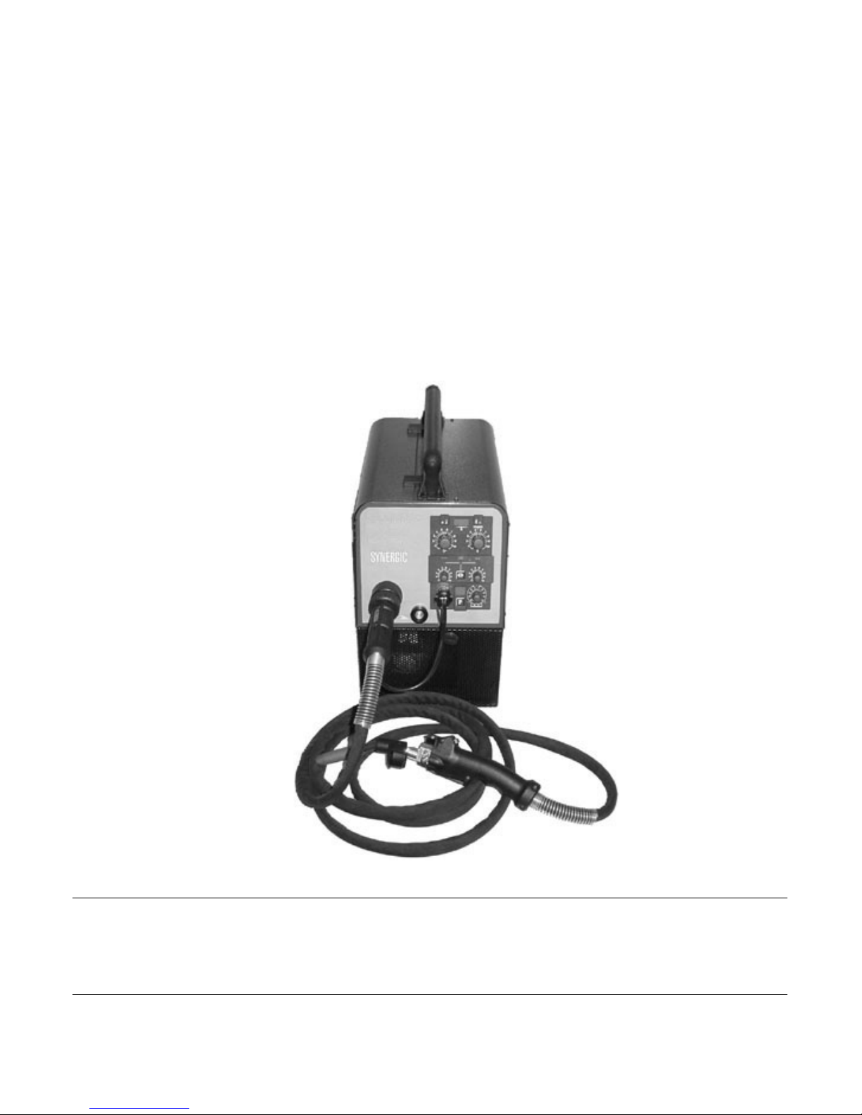
Questa saldatrice è un generatore realizzato con
tecnologia INVERTER, adatto alla saldatura
MIG/MAG e OPEN-ARC.
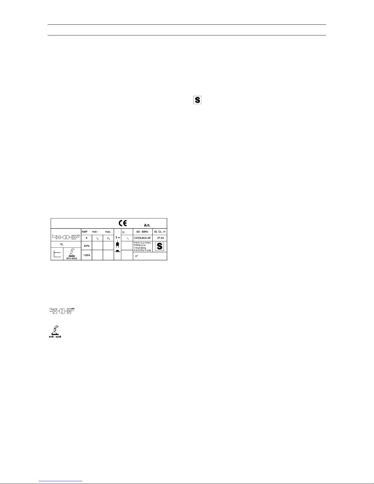
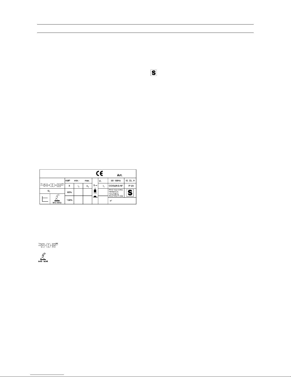
1.2 Spiegazione dei dati tecnici
1
Art. Articolo della macchina che deve
essere sempre citato per qualsiasi
richiesta relativa alla saldatrice.
n° Numero di matricola che deve essere
sempre citato per qualsiasi richiesta
relativa alla saldatrice.
Convertitore statico di frequenza
monofase-trasformatore-
raddrizzatore
Adatto per saldatura a filo
continuo (MIG/MAG).
AMP Corrente di saldatura non
convenzionale.
I valori rappresentano il limite minimo
e massimo ottenibile in saldatura.
Uo Tensione a vuoto secondaria (V di
picco)
X Fattore di servizio percentuale.
Il fattore di servizio esprime la
percentuale di 10 minuti in cui la
saldatrice può lavorare ad una
determinata corrente senza
causare surriscaldamenti.
I
2
Corrente di saldatura
U Tensione secondaria con corrente di
2
saldatura I
2
U Tensione nominale di alimentazione.
1
1~ 50/60Hz Alimentazione monofase 50 o 60 Hz.
I
1
Corrente assorbita alla corrispon-
dente corrente di saldatura I
2
IP23 Grado di protezione della carcassa.
Grado 3 come seconda cifra significa
che questo apparecchio è idoneo a
lavorare all’esterno sotto la pioggia.
Idonea a lavorare in ambienti con
rischio accresciuto.
NOTE: La saldatrice è inoltre stata progettata per
lavorare in ambienti con grado di inquinamento 3.
(Vedi IEC 664).
1.3 Protezioni
1.3.1 Protezione di blocco
In caso di malfunzionamento sul display G può
comparire un numero lampeggiante con il seguente
significato:
52 = pulsante di start premuto durante la
accensione.
53 = pulsante di start premuto durante il ripristino
del termostato.
56 = Cortocircuito prolungato tra il filo di saldatura
ed il materiale da saldare.
Spegnere e riaccendere la macchina.
Nel caso il display visualizzi numeri diversi
contattare il servizio assistenza.
1.3.2 Protezione meccanica (pulsante di
sicurezza)
Quando si apre il laterale mobile, si attiva il
pulsante di sicurezza che impedisce il
funzionamento della saldatrice. Questa protezione,
evidenziata dall’accensione del LED A, evita
situazioni di pericolo quando l'operatore sostituisce
il rullo del gruppo trainafilo o il filo di saldatura.
1.3.3 Protezione termica
Questo apparecchio è protetto da un termostato il
quale, se si superano le temperature ammesse,
impedisce il funzionamento della macchina. In
queste condizioni il ventilatore continua a
funzionare ed il LED A si accende.
2 INSTALLAZIONE
Controllare che la tensione d'alimentazione
corrisponda al valore indicato sulla targa dei dati
tecnici della saldatrice.
Collegare una spina di portata adeguata al cavo
d'alimentazione assicurandosi che il conduttore
giallo/verde sia collegato allo spinotto di terra.
La portata dell'interruttore magnetotermico o dei
fusibili, in serie all'alimentazione, devono essere
uguale alla corrente I
1
assorbita dalla macchina.
2.1 Messa in opera
L'installazione dalla macchina deve essere fatta da
personale esperto. Tutti i collegamenti devono
essere eseguiti in conformità e nel pieno rispetto
della legge antinfortunistica (norma CEI 26-10 CENELEC HD 427)
AVVERTENZA: Questa apparecchiatura non è
conforme alla normativa EN/IEC 61000-3-12. E’
2
l tempo di puntatura o di
termittenza. La
ia da 0,3 a 5 secondi.
a di saldatura.
zzata alla fine della saldatura,
USH-PULL P3KP, utilizzata con
(manuale per AL), il display indica
rzionale alla
ccensione della saldatrice.
iamo o aumentiamo il valore
urva sinergica.
nopola regola il tempo di pausa tra un
i
do il
n - rispetto allo 0 centrale,
ramma sinergico, potrebbe
responsabilità dell’installatore o dell’utilizzatore
(se necessario consultando il distributore della
rete) assicurarsi che l’apparecchiatura possa
essere collegata ad una linea pubblica in bassa
tensione.
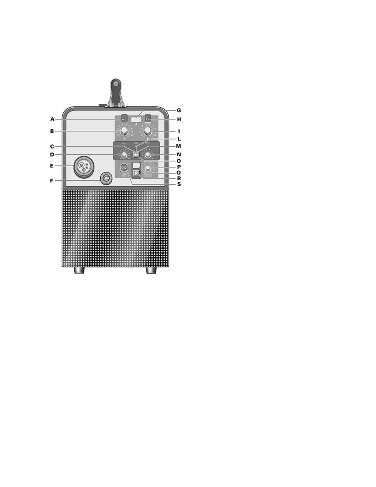
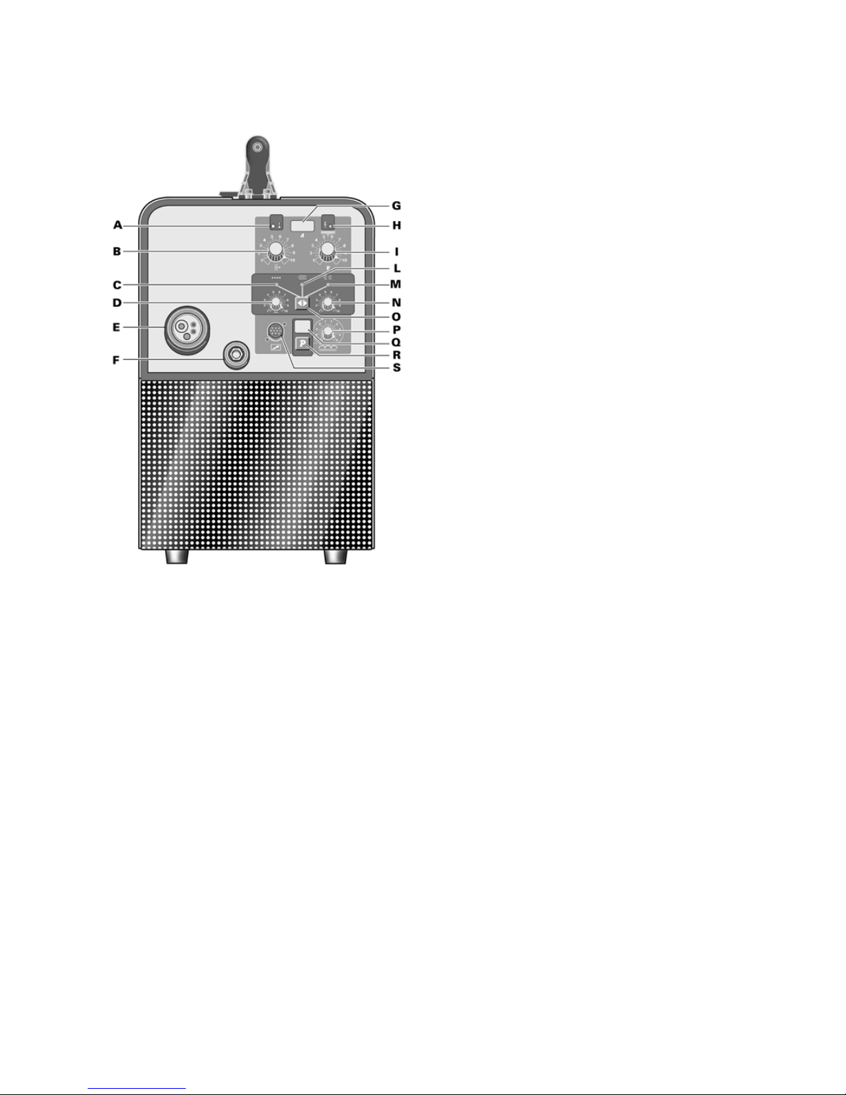
2.2 Comandi posti sul pannello anteriore
A - LED giallo.
Si accende quando il pulsante di sicurezza o il
termostato interrompono il funzionamento della
saldatrice.
B- Manopola di regolazione.
• Quando si utilizzano i programmi manuali varia
la velocità del filo di saldatura.
In questa condizione il display G indica solo la
corrente durante la saldatura.
• Quando si utilizzano i programmi sinergici
permette di preimpostare la corrente e di regolarla
durante la saldatura. La corrente è indicata, in
ogni condizione, dal display G.
Durante la saldatura questa corrente potrà variare
(anche se di poco) in funzione dello spessore del
materiale e dalla manualità dell'operatore. E'
indispensabile selezionare tramite il tasto R il
corretto programma di saldatura affinché il display
G indichi il giusto valore di corrente preimpostata.
C- LED colore verde.
Segnala l'attivazione del modo di saldatura per
punti o in intermittenza quando è acceso insieme
al LED M.
D- Manopola di regolazione.
Questa manopola regola i
lavoro durante la saldatura ad in
durata del tempo var
E- Attacco centralizzato
Vi si connette la torci
F- Presa di massa
Presa per il collegamento del cavo di massa.
G- Display 3 cifre.
Questo display visualizza la corrente di saldatura
che rimane memori
inoltre al momento della scelta del programma,
visualizza per un breve periodo il tipo di materiale
selezionato.
Con la torcia P
programma N° 2
un valore (variabile tra 1 e10) propo
velocità del filo.
H - LED verde.
Segnala l'a
I- Manopola di regolazione.
• Nei programmi manuali varia la tensione di
saldatura.
• Nei programmi sinergici, l'indice di questa
manopola deve essere posto sul simbolo
"SYNERGIC " al centro della regolazione. Agendo
su questa manopola si può correggere il valore
della tensione (lunghezza d'arco). L'operatore può
avere l'esigenza di modificare i valori memorizzati
per diversi motivi: una torcia diversa da quella
standard può dare piccole variazioni di
scorrevolezza del filo, la dimensione e lo spessore
della costruzione da saldare può avere bisogno di
piccole correzioni rispetto ai valori impostati, lo
stesso operatore, per sua abitudine o per proprie
esigenze può avere la necessità di variare la
tensione memorizzata.
E’ chiaro che se diminu
di tensione memorizzata, la correzione sarà ripetuta
sull'intera c
L- LED colore verde.
Segnala l'attivazione del modo di saldatura in
continuo.
M- LED colore verde.
Segnala l'attivazione del modo di saldatura in
intermittenza. Si accende assieme al LED C.
N- Manopola di regolazione.
Questa ma
tratto di saldatura e un altro. La durata del tempo
varia da 0,3 secondi a 5 secondi.
O- Tasto.
Premendo questo tasto si illuminano in sequenza
LED C, L e assieme i LED M e C.
P- Manopola di regolazione.
Questa manopola regola il valore dell'impedenza.
Per ogni programma il valore ottimizzato
corrisponde alla posizione 0. La macchina regola
automaticamente il corretto valore d'impedenza in
base al programma selezionato. L'operatore può
correggere il valore impostato e, regolan
potenziometro verso il +, otterrà saldature più calde
e meno penetranti, viceversa, regolando verso il -,
otterrà saldature più fredde e più penetranti.
La variazione in + o i
saldando con un prog
3
a 2 cifre.
.
nare quale programma
- Connettore 10 poli.
o il
macchina.
l
lo (+).
te il
riore della
-10 litri il minuto.
USH-PULL P3KP
assa al pezzo da
lla lancia
uoriesce.
si che il
saldare con fili
tti di saldatura.
te e ben protette
2
CO2 circa il 2%.
mani. E’ importante
richiedere una correzione della tensione di lavoro
con il potenziometro I.
Q- Display
Questo display visualizza il numero di programma
selezionato dal tasto R.
R- Tasto.
Questo tasto seleziona il numero di programma,
che è visualizzato dal display Q
Le istruzioni per determi
utilizzare sono indicate dentro una busta posta
all'interno del laterale mobile.
S
A questo connettore deve essere collegat
maschio 10 poli della torcia PUSH-PULL P3KP.
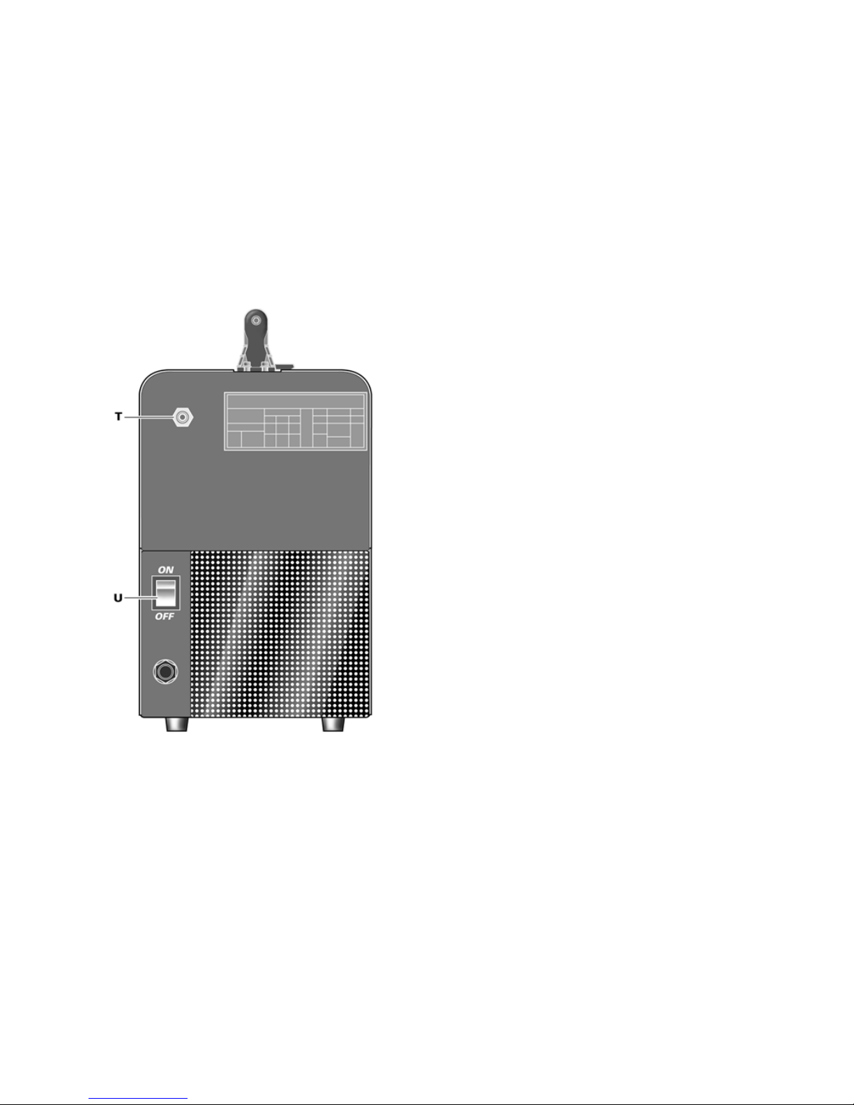
2.3 Comandi posti sul pannello posteriore
T- Raccordo gas.
U- Interruttore.
Accende e spegne la
3 SALDATURA
3.1 Messa in opera
Controllare che il diametro del filo corrisponda al
diametro indicato sul rullo trainafilo e che il
programma prescelto sia compatibile con il
materiale e il tipo di gas. Utilizzare rulli trainafilo
con gola ad “U” per fili di alluminio e con gola a
“V” per gli altri fili.
In base al tipo di filo da utilizzare assicurarsi che i
cavi corrispondenti alla torcia e al morsetto di
massa siano correttamente collegati sulla
morsettiera accessibile dallo sportello posto su
laterale destro della macchina.
Normalmente con i fili che richiedono protezione di
gas la torcia deve essere collegata al po
3.1.1 Collegamento del tubo gas
La bombola di gas deve essere equipaggiata da un
riduttore di pressione e un flussometro.
Se la bombola è posta sul pianale portabombole del
carrello deve essere fissata con l'apposita catena.
Solo dopo aver sistemato la bombola, collega
tubo gas uscente dalla parte poste
macchina al regolatore di pressione. Il flusso di gas
deve essere regolato a circa 8
3.2 La macchina è pronta per saldare
Quando si utilizza la torcia tipo P
gate. seguire le istruzioni alle
• Connettere il morsetto di m
saldare.
• Posizionare l'interruttore U su I.
• Togliere l'ugello gas.
• Svitare l'ugello portacorrente.
• Inserire il filo nella guaina guidafilo della torcia
assicurandosi che sia dentro la gola del rullo e che
questo sia in posizione corretta.
• Premere il pulsante torcia per fare avanzare il filo
fino alla fuoriuscita dello stesso dalla torcia.
il viso lontano da• Attenzione: tenere
terminale mentre il filo f
• Avvitare l'ugello portacorrente assicurando
diametro del foro sia pari al filo utilizzato.
• Montare l'ugello gas.
3.3 Saldatura degli acciai al carbonio
Per la saldatura di questi materiali è necessario:
3.3.1 Con protezione di gas
• Utilizzare un gas di saldatura a composizione
binaria, di solito ARGON + CO
2
con percentuali di
Argon che vanno dal 75% in su. Con questa
miscela il cordone di saldatura sarà ben raccordato
ed estetico.
Utilizzando CO
2
puro, come gas di protezione si
avranno cordoni stretti, con una maggiore
penetrazione ma con un notevole aumento di
proiezioni (spruzzi).
• Utilizzare un filo d'apporto della stessa qualità
rispetto all'acciaio da saldare. E' sempre bene
sare fili di buona qualità, evitare di u
arrugginiti che possono dare dife
• Evitare di saldare su pezzi arrugginiti o che
presentano macchie d'olio o grasso.
3.3.2 Senza protezione di gas
er ottenere saldature raccordaP
saldare sempre da sinistra a destra e dall'alto verso
il basso. Il filo animato Ø 0,9 deve essere utilizzato
con la torcia collegata al polo (-).
3.4 Saldatura degli acciai inossidabili
La saldatura degli acciai inossidabili della serie 300,
deve essere eseguita con gas di protezione ad alto
tenore di Argon, con una piccola percentuale di
ssigeno O o di anidride carbonicao
Non toccare il filo con le
mantenere sempre la zona di saldatura pulita per
non inquinare il giunto da saldare.

4
a al
specifiche per
lluminio senza mai usarle per altri materiali.
nio si deve utilizzare
ETTO sterne al
AUSE so (arrugginito
di gas
so
mancanza di
di
l gas intasati
. IFETTO
AUSE e sporchi
iccolo.
.
3. DIFETTO i laterali
ce
sioni di arco
CAUSE
• Induttanza insufficiente.
ldatore del
zione di CO
ve essere liberato
tto tra questo ugello ed il
servare i
esente da sporco od ossidazione.
te ostacolando l'uscita del
a ne possono creare un allentamento
scaldamento del corpo torcia e
ata
con aria compressa secca.
ad un continuo logorio,
o delle bobine. E' necessario
n controllo periodico di tutto il gruppo responsabile
del traino del filo: aspo, rullini guidafilo, guaina e
ugello porta corrente.
3.5 Saldatura dell'alluminio
Per la saldatura dell'alluminio è necessario
utilizzare:
• Argon puro come gas di protezione.
• Un filo di apporto di composizione adeguat
materiale base da saldare.
• Utilizzare mole e spazzonatrici
l'a
• Per la saldatura dell'allumi
la torcia PUSH-PULL P3KP.
4 DIFETTI IN SALDATURA
1. DIF - Porosità (interne o e
cordone)
C • Filo difetto
superficialmente)
• Mancanza di protezione
dovuta a:
- flusso di gas scarso
- flussometro difetto
- riduttore brinato, per la
un preriscaldatore del gas
protezione di CO
2
- elettrovalvola difettosa
- ugello porta corrente intasato da
spruzzi
- fori di efflusso de
- correnti d'aria presenti in zona di
saldatura.
2 D - Cricche di ritiro
C • Filo o pezzo in lavorazion
od arrugginiti.
• Cordone troppo p
• Cordone troppo concavo
• Cordone troppo penetrato.
- Incision
CAUSE • Passata troppo velo
• Corrente bassa e ten
elevate.
4 DIFETTO - Spruzzi eccessivi
• Tensione troppo alta.
• Mancanza di un prerisca
gas di prote
2
5 MANUTENZIONE DELL'IMPIANTO
• Ugello protezione gas
Questo ugello de
periodicamente dagli spruzzi metallici. Se distorto
o ovalizzato sostituirlo.
• Ugello porta corrente.
Soltanto un buon conta
filo assicura un arco stabile e un'ottima
erogazione di corrente; occorre perciò os
seguenti accorgimenti:
A) Il foro dell'ugello portacorrente deve essere
tenuto
B) A seguito di lunghe saldature gli spruzzi si
attaccano più facilmen
filo.
E' quindi necessario pulire spesso l'ugello e se
necessario sostituirlo.
C) L'ugello porta corrente deve essere sempre
ben avvitato sul corpo torcia. I cicli termici subiti
dalla torci
con conseguente ri
dell'ugello ed una incostanza dell'avanzamento del
filo.
• Guaina guidafilo.
E' una parte importante che deve essere controll
spesso poiché il filo può depositarvi polvere di rame
o sottilissimi trucioli. Pulirla periodicamente assieme
ai passaggi del gas,
Le guaine sono sottoposte
per cui si rende necessario, dopo un certo periodo,
la loro sostituzione.
• Gruppo motoriduttore.
Pulire periodicamente l'insieme dei rulli di
trascinamento da eventuale ruggine o residui
metallici dovuti al train
u
INSTRUCTION MANUAL FOR WIRE WELDING MACHINE
Before using this device all people authorised to
its use, repair or inspection, should read the
book “Safety rules for using machines” and the
“Instruction manual” specific for every machine.
Contact your distributor if you have not
understood some instructions.
IP23 Protection rating for the housing.
Grade 3 as the second digit means that
this equipment is suitable for use
outdoors in the rain.
Suitable for use in high-risk
environments.
IMPORTANT: Before starting the equipment, read
the contents of this manual, which must be stored in
a place familiar to all users for the entire operative
life-span of the machine.
NOTES: The welding machine has also been
designed for use in environments with pollution
rating of 3. (See IEC 664).
This equipment must be used solely for welding
operations.
1.3 Protections
IN CASE OF MALFUNCTIONS, REQUEST
ASSISTANCE FROM QUALIFIED PERSONNEL.
1.3.1 Block protection
In the event of a malfunction, a number with the
following meaning may appear on the display G:
1 GENERAL DESCRIPTIONS
52 = Start button pressed during start-up.
53 = start button pressed during thermostat reset.
1.1 Specifications
56 = Extended short-circuit between the welding
electrode and the material to be welded.
This equipment is a power source developed using
INVERTER technology, suitable for MIG/MAG and
OPEN-ARC welding.
Shut the machine off and turn it back on.
If different numbers appear on the display, contact
technical service.
1.2 Explanation of technical specifications
1.3.2 Mechanical protection (safety button)
When the movable side is opened, this activates
the safety button that prevents operation of the
welding machine. This protection, indicated when
the LED A is lit, avoids hazardous situations when
the operator replaces the roller of the wire feeder
unit or the welding electrode.
Art. Item number, which must be indicated on
1.3.3 Thermal protection
any type of request regarding the welding
This machine is protected by a thermostat, which
prevents the machine from operating if the
allowable temperatures are exceeded. Under these
conditions the fan keeps running and the LED A
lights.
machine
n°. Serial number, which must be indicated
on any type of request regarding the
welding machine.
Single-phase static transformer-rectifier
frequency converter.
2 INSTALLATION
Make sure that the supply voltage matches the
voltage indicated on the specification plate of the
welding machine.
Suitable for continuous electrode
(MIG/MAG) welding.
AMP Unconventional welding current.
Mounting a plug with an adequate capacity for the
supply cable, making sure that the yellow/green
conductor is connected to the earth pin.
The values represent the minimum and
maximum levels attainable in welding.
Uo Secondary open-circuit voltage (peak V)
The capacity of the overload cutout switch or fuses
installed in series with the power supply must be
equivalent to the absorbed current I
1
of the
machine.
X Duty cycle percentage.
The duty cycle expresses the percentage
of 10 minutes during which the machine
may run at a certain current without
overheating.
2.1 Setup
I
2
Welding current
Skilled personnel must install the machine. All
connections must be carried out according to
current regulations, and in full observance of safety
laws (regulation CEI 26-10 - CENELEC HD 427).
U
2
Secondary voltage with welding current I2
U
1
Rated supply voltage.
1~ 50/60Hz 50- or 60-Hz single-phase power
supply.
WARNING: This equipment does not comply with
IEC 61000-3-12. If it is connected to a public low
voltage system, it is the responsibility of the installer
or user of the equipment to ensure, by consultation
I
1
Absorbed current at the corresponding
welding current I
2
.
5
with the distribution network operator if necessary,
that the equipment may be connected.
2.2 Controls on the front panel
6
A- LED yellow.
Lights when the thermostat or safety button interrupt
operation of the welding machine.
B- Setting knob.
• Adjusts the welding wire speed when using manual
programs.
In this condition the display G indicates only the
current during welding.
• When using synergic programs, it allows you to
pre-set the current and adjust during welding. The
current is indicated, in all conditions, by the display
G.
During welding, this current may vary (although only
slightly) based on the thickness of the material and
the manual skill of the operator. It is essential to use
the R key to select the correct welding program so
that the display G indicates the correct pre-set
current value.
C- LED green.
Signals activation of the spot or dash-welding mode
when lit together with LED M.
D - Setting knob.
This knob adjusts the spot welding or working time
during dash welding. The duration ranges from 0,3
to 5 seconds.
E - Central adapter
This is where the welding torch is to be connected.
F- Earth socket
Grounding cable socket.
G- 3-Digit display.
This display shows the welding current, which
remains saved after welding; in addition, it briefly
displays the type of material selected when a
program is selected.
With the PUSH-PULL P3KP torch, used with
program N° 2 (manual for AL), the display shows a
value (between 1 and 10) in proportion to the wire
speed.
H - LED green.
Indicates that the welding machine is on.
I- Setting knob.
• Adjusts the welding voltage in manual programs.
• In synergic programs, the indicator of this knob
must be set to the "SYNERGIC " symbol in the
centre of the setting range. Adjusting this knob
allows you to correct the voltage value (arc length).
The operator may need to change the saved values
for various reasons: a non-standard torch may
change the wire movement slightly, the size and
thickness of the workpiece may require minor
corrections from the set values, the operator may
need to change the saved voltage out of habit or
due to his or her own needs.
Obviously, any increases or decreases to the saved
voltage value will be repeated throughout the
synergic curve.
L- LED green.
Indicates that continuous welding mode is
activated.
M- LED green.
Indicates that 2-stage manual dash welding mode is
activated. It lights together with LED C.
N- Setting knob.
This knob adjusts the pause time between spot
welds. The duration ranges from 0.3 to 5 seconds.
O- Key.
Press this key to light in sequence the LEDs C, L
along with the LEDs M and C.
P- Setting knob.
This knob adjusts the impedance value.
For each program, the optimum value is the 0
position.
The machine automatically sets the correct
impedance value based on the program selected.
The operator may correct the set value: adjusting
the potentiometer towards + will produce warmer,
less penetrating welds, while vice-versa adjusting
towards - will produce colder and more penetrating
welds.
When welding with a synergic program, adjusting +
or - from the central 0 may require corrections to
the working voltage using the potentiometer I.
Q- 2-Digit display.
This display shows the program number selected
by the R key.
R- Key.
This key selects the program number, which
appears on the display Q.
The instructions for deciding which program to use
are provided in a packet inside the mobile side
panel.
S- 10-Pin connector.
This connector must be connected to the 10-pin
male of the PUSH-PULL P3KP torch.

7
p to the workpiece.
groove and that the
ove the wire forward
he gun tube
le diameter is the same as that of the wire
Assemble the gas nozzle.
order to weld these materials you must:
the welding
netration but a
wires
g rusted parts or those with oil or
rease stains.
st be used with the torch
onnected to the (-) pole.
.4 Welding stainless steel
ioxide CO
mes, to avoid contaminating the joint to be welded.
.5 Welding aluminium
se:
tion suitable for
inium, and never use them for
m you must use the
torch PUSH-PULL P3KP.
WELDING DEFECTS
.
2.3 Controls on the rear panel
T- Gas hose fitting.
U- Switch.
Turns the machine on and off.
3 WELDING
3.1 Installation
Make sure that the wire diameter corresponds to the
diameter indicated on the wire feeder roller, and that
the selected program is compatible with the material
and type of gas. Use wire feeder rollers with a "U"shaped groove for aluminium wires, and with a "V"shaped groove for other wires.
Based on the type of wire to be used, make sure
that the cables corresponding to the torch and earth
clamp are properly connected to the terminal board
accessible from the door on the right-hand side of
the machine.
Normally, with wires that require gas protection, the
torch must be connected to the (+) pole.
3.1.1 Connecting the gas hose
The gas cylinder must be equipped with a pressure
regulator and flow gauge.
If the gas cylinder is placed on the cylinder shelf of
the trolley it must be fastened using the chain
provided.
Connect the gas hose leaving the rear of the
machine to the pressure regular, only after
positioning the cylinder. The gas flow must be
adjusted to approximately 8-10 litres per minute.
3.2 The machine is ready to weld
When using the PUSH-PULL P3KP torch, follow the
instructions enclosed.
• Connect the earth clam
• Set the switch U to I.
• Remove the gas nozzle.
• Unscrew the contact tip.
• Insert the wire in the wire liner of the torch, making
sure that it is inside the roller
roller is in the correct position.
• Press the torch trigger to m
until it comes out of the torch.
• Caution: keep your face away from t
assembly while the wire is coming out.
• Screw the contact tip back on, making sure that
the ho
used.
•
3.3 Welding carbon steel
In
3.3.1 With gas protection
• Use a welding gas with a binary composition,
usually ARGON + CO
2
with percentages of Argon
ranging from 75% up. With this blend,
bead will be well jointed and attractive.
Using pure CO
2
as a protection gas will produce
narrow beads, with greater pe
considerably increase in splatters.
• Use a welding wire of the same quality as the
steel to be welded. It is best to always use good
quality wires, avoiding welding with rusted
that could cause welding defects.
• Avoid weldin
g
3.3.2 Without gas protection
To achieve well connected and protected welds,
always work from left to right and top to bottom. The
flux-cored wires Ø 0,9 mu
c
3
Series 300 stainless steels must be welded using a
protection gas with high Argon content, containing a
small percentage of O
2
or carbon d
2
(approximately 2%) to stabilize the arc.
Do not touch the wire with your hands. It is
important to keep the welding area clean at all
ti
3
In order to weld aluminium you must u
• Pure Argon as the protection gas.
• A welding wire with a composi
the base material to be welded.
• Use mills and brushing machines specifically
designed for alum
other materials.
• In order to weld aluminiu
4
1 DEFECT - Porosity (within or outside the bead)

8
CAUSES
ing gas due to:
preheating
atter
area.
.
CAUSES e dirty or rusted.
penetrated.
.
CAUSES
. g
CAUSES
f the CO
2
protection
gas
MAINTAINING THE SYSTEM
ove
lace if distorted or squashed.
must therefore observe the following
must be kept free of grime
ter long welding
cleaned more often,
d tip and causing the
ce unevenly.
long with the gas
ust be replaced after a certain
group:
asp, wire guide rollers, liner and contact tip.
• Electrode defective (rusted surface)
• Missing shield
- low gas flow
- flow gauge defective
- regulator frosted due to no
of the CO
2
protection gas
- defective solenoid valve
- contact tip clogged with sp
- gas outlet holes clogged
- air drafts in welding
2 DEFECT - Shrinkage cracks
• Wire or workpiec
• Bead too small.
• Bead too concave.
• Bead too deeply
3 DEFECT - Side cuts
• Welding pass done too quickly
• Low current and high arc voltages.
4 DEFECT - Excessive sprayin
• Voltage too high.
• Insufficient inductance.
• No preheating o
5
• Shielding gas nozzle.
This nozzle must be periodically cleaned to rem
weld spatter. Rep
• Contact tip.
Only a good contact between this contact tip and the
wire can ensure a stable arc and optimum current
output; you
precautions:
A) The contact tip hole
and oxidation (rust).
B) Weld spatter sticks more easily af
sessions, blocking the wire flow.
C) The tip must therefore be
and replaced if necessary.
D) The contact tip must always be firmly screwed
onto the torch body. The thermal cycles to which
the torch is subjected can cause it to loosen, thus
heating the torch body an
wire to advan
• Wire liner.
This is an important part that must be checked often,
because the wire may deposit copper dust or tiny
shavings. Clean it periodically a
lines, using dry compressed air.
The liners are subjected to constant wear and tear,
and therefore m
amount of time.
• Gearmotor group.
Periodically clean the set of feeder rollers, to remove
any rust or metal residue left by the coils. You must
periodically check the entire wire feeder
h
 Loading...