

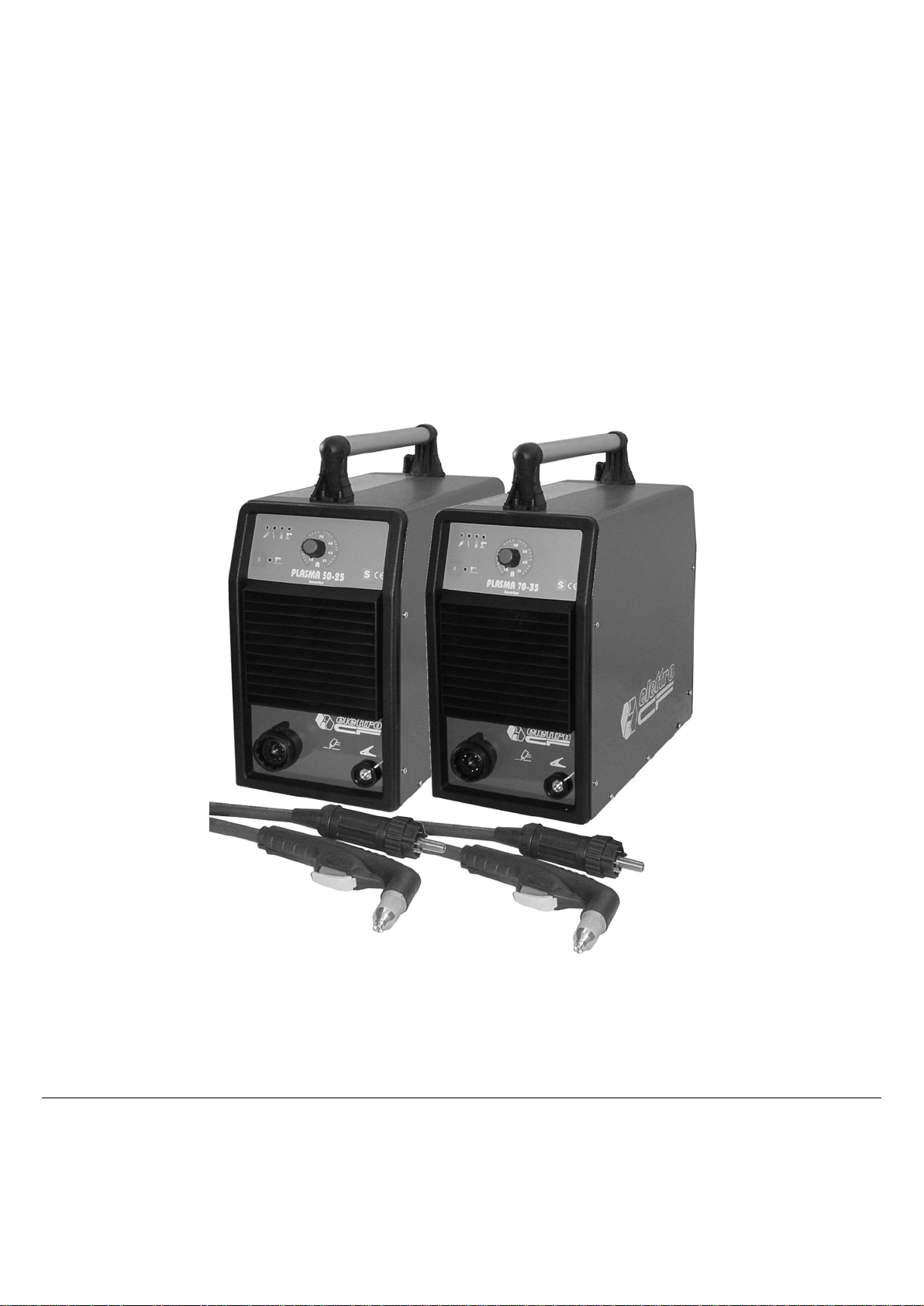
Elettro CF 50-25, Plasma Series, 70-35, 120-60, 51 PFC Instructions Manual
IT MANUALE DI ISTRUZIONI PER APPARECCHI DI TAGLIO AL PLASMA .................... Pag. 3
EN INSTRUCTIONS FOR PLASMA CUTTERS .................................................................... Page 8
DE BETRIEBSANLEITUNG FÜR PLASMASCHNEIDGERÄTE ............................................ Seite 13
FR MANUEL D’INSTRUCTIONS POUR APPAREILS DE DECOUPE .................................. Page 18
ES MANUAL DE INSTRUCCIONES PARA EQUIPOS DE CORTE EN PLASMA ................ Pag. 23
PT MANUAL DE INSTRUÇÃO PARA APARELHOS DE CORTE AO PLASMA .................. Pag. 28
Parti di ricambio e schema elettrico
Spare parts and wiring diagram
Ersatzteile und elektrischer Schaltplan
Pièces de rechanges et schéma électrique
Partes de repuesto y esquema eléctrico
Peças e esquema eléctrico ........................................................................................................................ Pagg. Seiten
33
2
Items / Artt. 452 - 454
1
2
3
3
MANUALE DI ISTRUZIONI PER APPARECCHIO DI TAGLIO AL PLASMA
IMPORTANTE
PRIMA DELLA INSTALLAZIONE, DELL’USO O DI
QUALSIASI MANUTENZIONE ALLA MACCHINA
LEGGERE IL CONTENUTO DI QUESTO MANUALE E
DEL MANUALE “REGOLE DI SICUREZZA PER L’USO
DELLE APPARECCHIATURE” PONENDO PARTICOLARE
ATTENZIONE ALLE NORME DI SICUREZZA.
CONTATTARE IL VOSTRO DISTRIBUTORE SE NON
AVETE COMPRESO COMPLETAMENTE QUESTE
ISTRUZIONI.
Questo apparecchio deve essere utilizzato esclusivamente
per operazioni di taglio.
E’ inoltre indispensabile tenere nella massima
considerazione il manuale riguardante le regole di
sicurezza. I simboli posti in prossimità dei paragrafi ai quali
si riferiscono, evidenziano situazioni di massima
attenzione, consigli pratici o se mplici inf or mazioni.
Entrambi i manuali devono essere conservati con cura, in
un luogo noto ai vari interessati. Dovranno essere
consultati ogni qual volta vi siano dubbi, dovranno seguire
tutta la vita operativa della macchina e saranno impiegati
per l’ordinazione delle parti di ricambio.
1. INSTALLAZIONE
1.1. MONTAGGIO TORCIA
Questo impianto è idoneo solo per torce originali
ELETTROCF. Si declina ogni responsabilità se
utilizzato con torce di tipo diverso.
Inserire la torcia sul raccordo I (vedere fig. 1) utilizzando
l’apposito utensile in dotazione e avvitando a fondo la
ghiera onde evitare perdite d’aria che potrebbero
danneggiare o pregiudicare il buon funzionamento della
torcia.
Non ammaccare il perno portacorrente e non piegare gli
spinotti del raccordo torcia. Un’ammaccatura del perno
impedisce di scollegarlo, mentre uno spinotto piegato non
garantisce un buon inserimento sul raccordo fisso I,
impedendo il funzionamento dell’apparecchio.
Pneumatica:
Post a sul l’alimentazione della torcia per evitare che
la pressione aria sia insufficiente. E’ evidenziata
dall’accensione del led D (vedi fig.1).
Se il led D si accende significa che la pressione è scesa
momentaneamente al di sotto di 3,2 ÷ 3,5 bar.
Elettrica:
Posta sul corpo torcia, per evitare che vi siano tensioni
pericolose sulla torcia, quando si sostituiscono l’ugello, il
diffusore, l’elettrodo o il portaugello;
Non eliminare o cortocircuitare le sicurezze
Utilizzare solamente ricambi originali.
Sostituire sempre eventuali parti danneggiate
dell’apparecchio o della torcia con materiale originale.
Non far funzionare l’apparecchio senza i coperchi.
Questo sarebbe pericoloso per l’operatore e le persone che
si trovano nell’area di lavoro ed impedirebbe
all’apparecchio un raffreddamento adeguato.
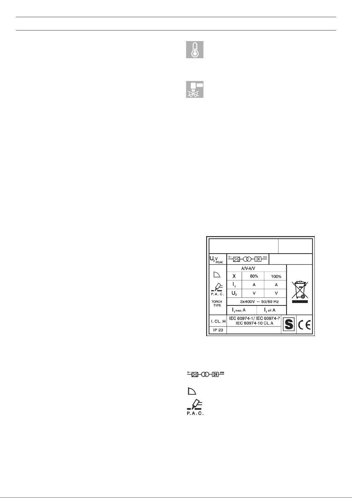
1.4. SPIEGAZIONE DEI DATI TECNICI
1.2. DESCRIZIONE DISPOSITIVI SULL’APPARECCHIO
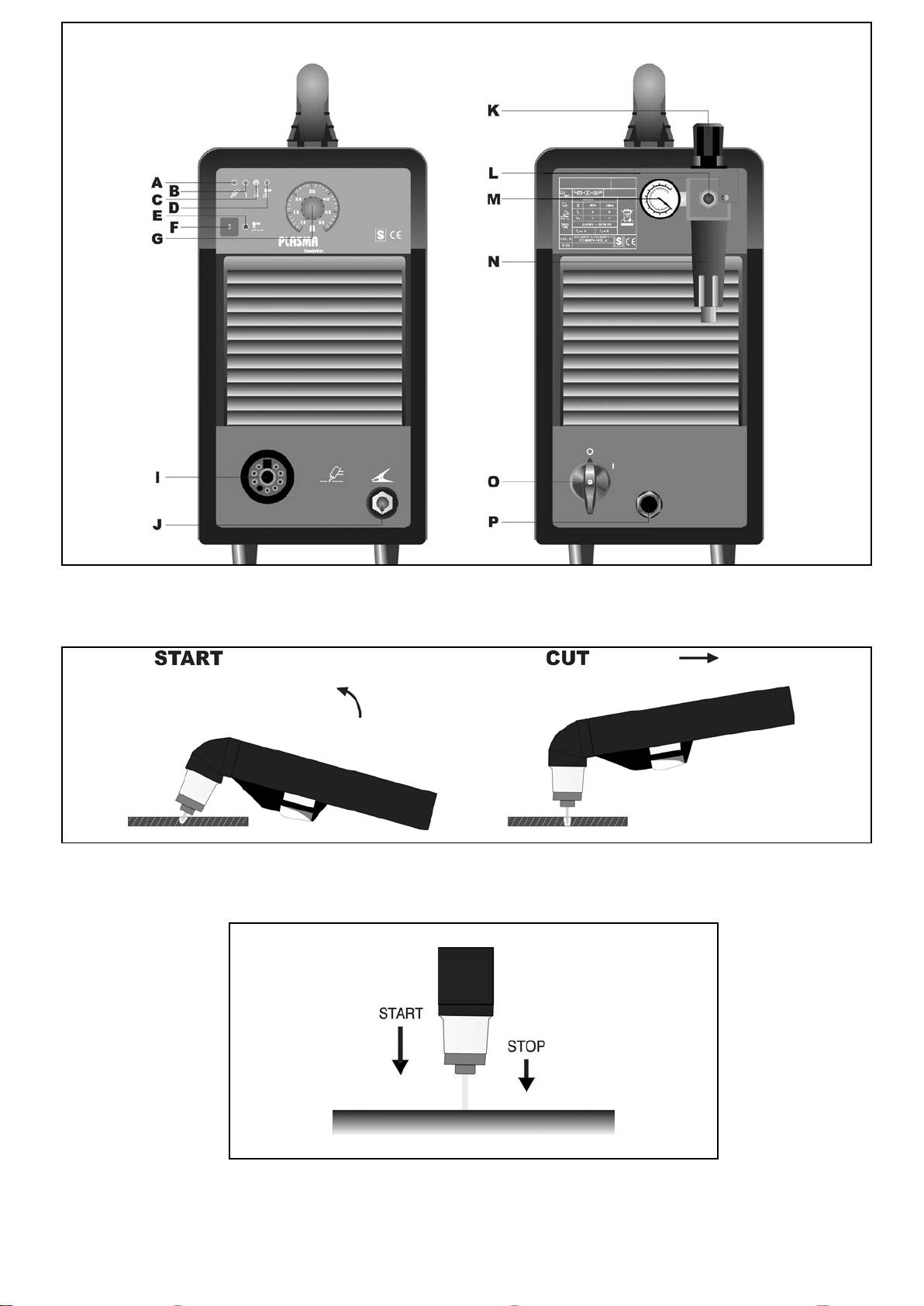
(Fig. 1)
A) Led spia di rete.
B) Led di blocco; si illumina in condizioni di pericolo
(vedi par. 5.1.1).
C) Led termostato
D) Led pressione aria insufficiente.
E) Led che s'illumina quando è attiva la funzione
"self-restart pilot"
F) Pulsante per attivare e disattivare la funzione di
“self-restart pilot”
G) Manopola di regolazione della corrente di taglio
I) Raccordo per torcia.
J) Morsetto di massa
K) Manopola regolazione pressione.
L) Raccordo aria compressa (filetto 1/4" gas
femmina)
M) Manometro
N) Vaschetta raccogli condensa
O) Interruttore di rete
P) Cavo di alimentazione
1.3. DISPOSITIVI DI SICUREZZA
Questo impianto è provvisto delle seguent i sic urez z e:
T
ermica:
Per evitare sovraccarichi. E’ evidenziata
dall’accensione continua del led C (vedi fig.1).
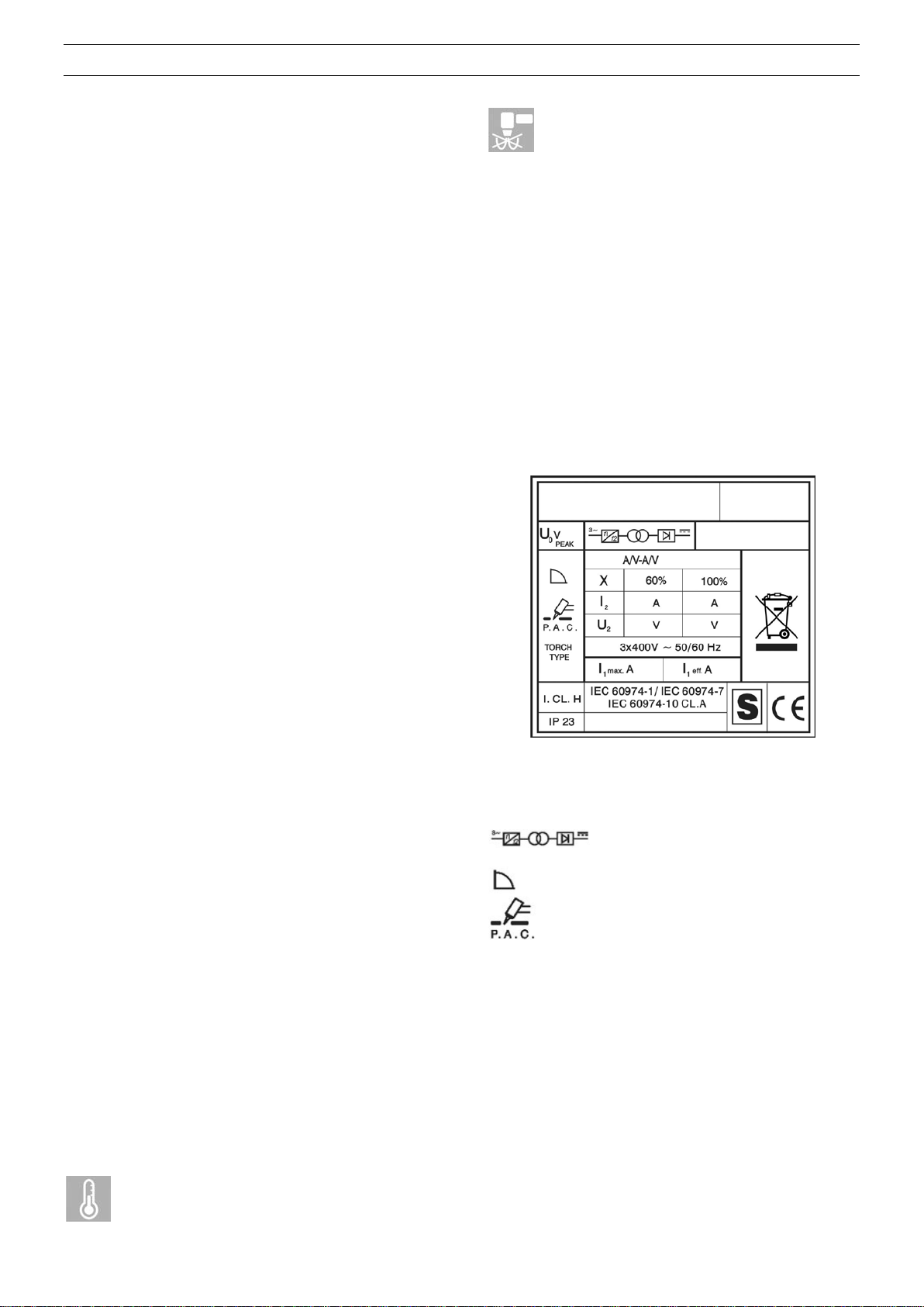
IEC 60974-1 ....... L’apparecchio è costruito secondo
IEC 60974-10 queste norme.
IEC 60974-7
Cl.A ..................... Apparecchiatura per uso industriale e
professionale.
.. Convertitore statico di frequenza trifase
trasformatore-raddrizzatore.
.................... Caratteristica discendente.
............... Adatto per il taglio al plasma.
TORCH TYPE .... Tipo di torcia che deve essere utilizzata
con questo apparecchio per formare un
sistema sicuro.
U0 ....................... Tensione a vuoto secondaria.
X ......................... Fattore di servizio percentuale.
Il fattore di servizio esprime la
percentuale di 10 minuti in cui
l’apparecchio può lavorare ad una
determinata corrente I2 e tensione U2
senza causare surriscaldamen ti.
I2 ......................... Corrente di taglio.
U
....................... Tensione convenzionale secondaria con
2
corrente di taglio I
Questa tensione
2
dipende dalla distanza tra l’ugello e il
pezzo da tagliare. Se questa distanza
aumenta anche la tensione di taglio
aumenta ed il fattore di servizio X% può
diminuire.

4
U1 ........................ Tensione nominale di alimentazione.
3~ 50/60Hz ........ Alimentazione trifase 50 oppure 60 Hz
I
Max .................. Corrente max. assorbita alla
1
corrispondente corrente I2 e tensione U2.
I
eff ................... E’ il massimo valore della corrente
1
effettiva assorbita considerando il fattore
di servizio. Solitamente, questo valore
corrisponde alla portata del fusibile (di
tipo ritardato) da utilizzare come
protezione per l’apparecchio.
IP23 .................... Grado di protezione del la carc ass a.
Grado 3 come seconda cifra significa che
questo apparecchio è idoneo a lavorare
all’esterno sotto la pioggia.
.................... Idoneo a lavorare in ambienti con rischio
accresciuto.
NOTE: L’apparecchio è inoltre stato progettato per lavorare
in ambienti con grado di inquinamento 3. (Vedi IEC 664).
1.5. MESSA IN OPERA
L’installazione d
ell’apparecchio deve essere fatta da
personale qualificato.
Tutti i collegamenti devono essere eseguiti in conformità
alle vigenti norme e nel pieno rispetto della legge
antinfortunistica (vedi CEI 26-23 / IEC-TS 62081).
Collegare l’alimentazione dell’aria al raccordo L (fig. 1).
Nel caso che l’alimentazione dell’aria provenga da un
riduttore di pressione di un compressore o di un impianto
centralizzato il riduttore deve essere regolato ad una
pressione di uscita non superiore a 8 bar (0,8 MPa).
Se l’alimentazione dell’aria proviene da una bombola di
aria compressa questa deve essere equipaggiata con un
regolatore di pressione.
Non collegare mai una bombola di aria compressa
direttamente al riduttore dell’apparecchio!
La pressione potrebbe superare la capacità del
riduttore che quindi potrebbe esplodere!
Collegare il cavo di alimentazione P (fig. 1): il conduttore
giallo verde del cavo deve essere collegato ad un’efficiente
presa di terra dell’impianto; i rimanenti conduttori debbono
essere collegati alla linea di alimentazione attraverso un
interruttore posto, possibilmente, vicino alla zona di taglio
per permettere uno spegnimento veloce in caso di
emergenza.
La portata dell’interruttore magnetotermico o dei fusibili in
serie all’interruttore deve essere uguale alla corrente I
eff
1
assorbita dall’apparecchio.
La corrente I
eff assorbita si deduce dalla lettura dei dati
1
tecnici riportati sull’apparecchio in corrispondenza della
tensione di alimentazione U1 a disposizione.
Eventuali prolunghe debbono essere di sezione adeguata
alla corrente I1 max assorbita.
2. IMPIEGO (vedere fig. 1)
Assicurarsi che il pulsante di start non sia premuto.
Accendere l’apparecchio mediante l’interruttore O. Questa
operazione sarà evidenziata dall’accensione della lampada
spia A.
Regolare la pressione, indicata dal manometro M, a 5 bar
(0,5 MPa) agendo sulla manopola K del riduttore, quindi
bloccare detta manopola premendo verso il basso.
Collegare il morsetto di massa al pezzo da tagliare.
Il circuito di taglio non deve essere posto deliberatamente a
contatto diretto o indiretto con il conduttore di protezione se
non nel pezzo da tagliare.
Se il pezzo in lavorazione viene collegato deliberatamente
a terra attraverso il conduttore di protezione, il
collegamento deve essere il più diretto possibile ed
eseguito con un conduttore di sezione almeno uguale a
quella del conduttore di ritorno della corrente di taglio e
connesso al pezzo in lavorazione nello stesso punto del
conduttore di ritorno utilizzando il morsetto del conduttore
di ritorno oppure utilizzando un secondo morsetto di massa
posto immediatamente vicino.
Ogni precauzione deve essere presa per evitare correnti
vaganti.
Scegliere, mediante la manopola G, la corrente di taglio.
Per art. 452: usare un ugello di diametro 0,95.
Per art. 454: usare un ugello di diametro 1,10.
Assicurarsi che il morsetto di massa e il pezzo siano in
buon contatto elettrico in particolare con lamiere verniciate,
ossidate o con rivestimenti iso l anti.
Non collegare il morsetto di massa al pezzo di materiale
che deve essere asportato.
Premere il pulsante della torcia per accendere l’arco pilota.
Se dopo 2 secondi non si inizia il taglio, l’arco pilota si
spegne e quindi, per riaccenderlo, è necessario premere
nuovamente il pulsante.
Tenere la torcia verticale durante il taglio.
Completato il taglio e dopo aver lasciato il pulsante, l’aria
continua ad uscire dalla torcia per circa 100 secondi per
consentire alla torcia stessa di raffreddarsi.
E’ bene non spegnere l’apparecchio prima della fine di
questo tempo.
Nel caso si debbano eseguire fori o si debba iniziare il
taglio dal centro del pezzo si deve disporre la torcia in
posizione inclinata e lentamente raddrizzarla in modo che il
metallo fuso non sia spruzzato sull’ugello (vedi fig. 2).
Questa operazione deve essere eseguita, quando si forano
pezzi di spessore superiore ai 3 mm.
Nell'impiego in automatico, per lo sfon dament o (vedi fig. 3)
partire con l'ugello ad una distanza dal pezzo superiore a
quella del taglio.
Per spessori superiori a:
10 mm per art. 452
14 mm per art. 454
è necessario perforare il materiale prima del taglio.
Nel caso si debbano eseguire tagli circolari si consiglia di
utilizzare l’apposito compasso fornito a richiesta.
E' importante ricordare che l'utilizzo del compasso può
rendere necessario impiegare la tecnica di partenza
suindicata (vedi fig. 2).
Non tenere inutilmente acceso l’arco pilota in aria per non
aumentare il consumo dell’elettrodo, del diffusore e
dell’ugello.
A lavoro terminato, spegnere la macchina.
Per tagliare lamiere forate o grigliati attivare la
speciale funzione mediante il pulsante F (led E acceso).
Alla fine del taglio, mantenendo premuto il pulsante, l'arco
pilota si riaccenderà automaticamente. Utilizzare questa
funzione solo se necessario per evitare un'inutile usura
dell'elettrodo e dell'ugello.
3. INCONVENIENTI DI TAGLIO
3.1. INSUFFICIENTE PENETRAZIONE
Le cause di questo inconveniente possono essere:
velocità elevata. Assicurarsi sempre che l’arco sfondi
completamente il pezzo da tagliare e che non abbia
mai un’inclinazione, nel senso di avanzamento,
superiore ai 10 -15°. Si eviteranno consumi non
corretti dell’ugello e bruciature al portaugello.
Spessore eccessivo del pezzo.

5
Morsetto di massa non in buon contatto elettrico con il
LED B
CONDIZIONE
RIMEDIO
Attendere 5 sec.
della macchina.
Acceso
fisso
Tensione di pilotaggio
degli IGBT non corretta.
Contattare
l’assistenza.
Contatto del reed chiuso
della macchina.
pezzo.
Ugello ed elettrodo consumati.
Corrente di taglio troppo bassa.
N.B.: Quando l’arco non sfonda le scorie di metallo fuso
ostruiscono l’ugello.
3.2. L’ARCO DI TAGLIO SI SPEGNE
dell’apparecchio dalla polvere metallica accumulatasi,
usando aria compressa.
5.1.1 DIAGNOSI
Il led B (fig . 1) si accende quando si verificano le seguenti
condizioni:
Le cause di questo inconveniente possono essere:
ugello, elettrodo o diffusore co nsumati
pressione aria troppo alta
tensione di alimentazione troppo bassa
3.3. TAGLIO INCLINATO
Qualora il taglio si presentasse inclinato spegnere
l’appar ecchio e sostituire l’ugello.
Quando la corrente di taglio supera 45 A evitare che
l’ugello vada in contatto elettrico con il pezzo da tagliare
(anche attraverso scorie di metallo fuso), questa
condizione provoca una rapida, a volte istantanea,
distruzione del foro dell’ugello che provoca un taglio di
pessima qualità.
3.4. ECCESSIVA USURA DEI PARTICOLARI DI
CONSUMO
Le cause di questo proble ma possono essere:
a) pressione aria troppo bassa rispetto a quella consigliata.
b) eccessive bruciature sulla parte terminale del
portaugello.
4. CONSIGLI PRATICI
Se l’aria dell’impianto contiene umidità ed olio in
quantità notevole è bene utilizzare un filtro essiccatore
per evitare un’eccessiva ossidazione ed usura delle
parti di consumo, il danneggiamento della torcia e che
vengano ridotte la velocità e la qualità del taglio.
Le impurità presenti nell’aria favoriscono l’ossidazione
dell’elettrodo e dell’ugello e possono rendere
difficoltosa l’accensione dell’arco pilota. Se si verifica
questa condizione pulire la parte terminale
dell’elettrodo e l’interno dell’ugello con carta abrasiva
fine.
Assicurarsi che l’elettrodo e l’ugello nuovi che stanno
per essere montati siano ben puliti e sgrassati.
Per evitare di danneggiare la torcia utilizzare
sempre ricambi originali.
5. MANUTENZIONE
Togliere sempre l'alimentazione all’apparecchio prima di
ogni intervento che deve essere eseguito da personale
qualificato.
Acceso
fisso
Acceso
fisso
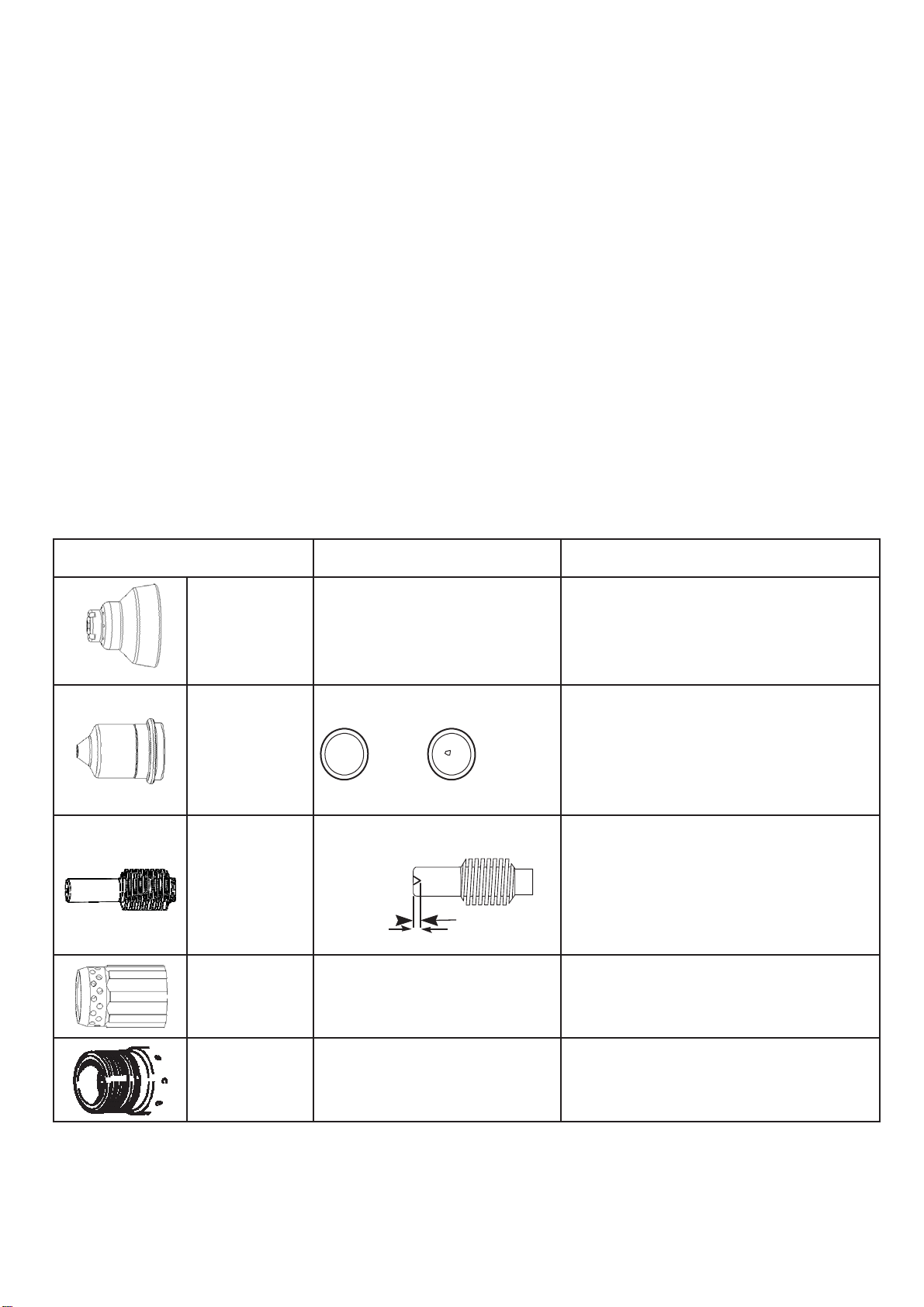
5.2. MANUTENZIONE TORCIA (vedi pag. 33, 35, 37 e 39)
Sostituzione delle parti di consumo. I particolari soggetti
ad usura sono l'elettrodo 23, il diffusore 24 e l'ugello 25. La
sostituzione di una di queste parti è possibile solo dopo
avere svitato il portaugello 26. L'elettrodo 23 deve essere
sostituito quando presenta un cratere al centro profondo
circa 1,5 mm. L'ugello 25 va sostituito quando presenta il
foro centrale rovinato oppure molto allargato rispetto a
quello del particolare nuovo.
Quando l'elettrodo è consumato l'ugello si usura molto
rapidamente. Quando l'elettrodo è usurato la macchina
perde potenza di taglio. Una ritardata sostituzione
dell'elettrodo e dell'ugello provoca un eccessivo
riscaldamento delle parti, tale da pregiudicare la durata del
diffusore 24. Assicurarsi che dopo la sostituzione, il
portaugello 26 sia stretto a sufficienza.
ATTENZIONE! Il portaugello 26 deve essere avvitato
sulla testina solo con l'elettrodo 23, il diffusore 24 e
l'ugello 25 montati.
5.3. ACCORGIMENTI DA USARE DOPO UN
Dopo aver eseguito una riparazione, fare attenzione a
riordinare il cablaggio in modo che vi sia un sicuro
isolamento tra il lato primario ed il lato secondario della
macchina. Evitare che i fili possano andare a contatto con
parti in movimento o parti che si riscaldano durante il
funzionamento. Rimontare tutte le fascette come
sull’apparecchio originale in modo da evitare che, se
accidentalmente un conduttore si rompe o si scollega,
possa avvenire un collegamento tra il primario ed il
secondario.
Rimontare inoltre le viti con le rondelle dentellate come
sull’apparecchio original e.
All’accensione della
macchina.
durante l’accensione
INTERVENTO DI RIPARAZIONE.
dall’accensione
Contattare
l’assistenza.
5.1. MANUTENZIONE GENERATORE
In caso di manutenzione all'interno dell’apparecchio,
assicurarsi che l'interruttore O (fig. 1) sia in posizione "O" e
che il cavo di alimentazione sia scollegato dalla rete.
Verificare inoltre che non vi sia tensione ai capi dei
condensatori del gruppo IGBT.
Anche se l’apparecchio è provvisto di un dispositivo
automatico per lo scarico della condensa, che entra in
funzione ogni volta che si chiude l’alimentazione dell’aria, è
buona norma, periodicamente, controllare che nella
vaschetta N (fig.1) del riduttore non vi siano tracce di
condensa.
Periodicamente, inoltre, è necessario pulire l’interno
6. CONSIGLI PRATICI PER TAGLIO AUTOMATICO
6.2. Informazioni e ottimizzazione della qualità di taglio
Le informazioni riportate nelle seguenti sezioni saranno utili
per ottimizzare la qualità di taglio e massimizzare la vita utile
dei consumabili.
6.1. Verifica della corretta configurazione della torcia e del
banco
• Posizionare la torcia ad angolo retto rispetto alla lamiera.
• Se si puliscono, controllano e "ottimizzano" le guide e il
sistema di trasmissione del banco da taglio, il movimento della
torcia è agevolato. Un movimento irregolare della macchina
può generare ondulazioni sulla superficie di taglio.
• Assicurarsi che durante il taglio la torcia non tocchi la
lamiera. Il contatto potrebbe danneggiare lo schermo e/o
l'ugello e influenzare la qualità della superficie di taglio.
Causa
Problema
Nella qualità del taglio è necessario tener conto di diversi
fattori:
1) Angolo di taglio: il livello di angolazione del bordo di
taglio.
2) Bava: il materiale fuso che si solidifica sulla parte
superiore o inferiore della lamiera.
3) Rettilineità della superficie di taglio: la superficie di taglio
può essere concava o convessa.
Nelle sezioni seguenti viene spiegato in che modo tali fattori
possono influenzare la qualità di taglio.
1) Angolo di taglio o di inclinazione
• Un angolo di taglio positivo viene realizzato quando viene
rimossa una quantità maggiore di materiale dalla parte
superiore del taglio anziché dal fondo.
• Un angolo di taglio negativo si ottiene quando viene rimossa
una quantità maggiore di materiale dalla parte inferiore del
taglio.
.
Soluzione
Taglio inclinato negativo
aglio OK
T
Taglio inclinato positivo
Note: L'angolo di taglio retto sarà sempre sul lato destro
caratterizzato da un determinato livello di inclinazione.
2) Bava
Quando si esegue il taglio plasma ad aria, si formerà sempre
un po' di bava. È tuttavia possibile ridurre al minimo la quantità
e il tipo di bava regolando correttamente il sistema in base
all'applicazione.
Le bave appaiono sul bordo superiore di entrambi i pezzi della
lamiera quando la torcia è troppo bassa o la tensione è troppo
alta, se si utilizza un controllo altezza torcia. Regolare la torcia
o la tensione in piccoli incrementi fino a ridurre la bava.
La bava a bassa velocità si forma quando la velocità di taglio
della torcia è eccessivamente bassa e l'arco spara in avanti.
Forma un deposito pesante e con bolle sul fondo del taglio e
può essere rimosso facilmente. Aumentare la velocità per
ridurre questo tipo di bava.
La bava ad alta velocità si forma quando la velocità di taglio è
eccessivamente elevata e l'arco rimane indietro. Forma una
bolla sottile e lineare di metallo solido attaccata molto vicino al
taglio. È saldata sul fondo del taglio ed è difficile da rimuovere.
Per ridurre la bava ad alta velocità:
• Diminuire la velocità di taglio.
• Diminuire la distanza tra la torcia e la lamiera.
La torcia è troppo bassa.
La torcia è troppo alta. Abbassare la torcia o, se si utilizza un controllo
rispetto al movimento in avanti della torcia. Il lato sinistro sarà sempre
Sollevare la torcia o, se si utilizza un controllo
dell'altezza della torcia, aumentare la tensione
dell'arco.
altezza torcia, diminuire la tensione dell'arco.
3) Rettilineità della superficie di taglio
Una tipica superficie di taglio al plasma è
leggermente concava.
La superficie di taglio può diventare più concava o
convessa. È necessario impostare correttamente
l'altezza della torcia per assicurare che la
superficie di taglio sia il più possibile retta. I
consumabili usurati influenzano inoltre la
rettilinearità del taglio.
Quando la distanza tra la torcia e la lamiera è
eccessivamente ridotta, si crea una superficie di
taglio estremamente concava. Aumentare la
distanza tra la torcia e la lamiera in modo da
raddrizzare la superficie di taglio.
Quando la distanza tra la torcia e la lamiera è
eccessivamente ampia o la corrente di taglio è
troppo alta, si crea una superficie di taglio
convessa. Provare innanzitutto ad abbassare la
torcia, quindi ridurre la corrente di taglio.
6
6.3. Sfondamento della lamiera mediante una torcia
automatica
Al pari della torcia per taglio manuale, è possibile iniziare un
taglio con la torcia automatica sul bordo della lamiera oppure
sfondando la lamiera. Lo sfondamento causerà una vita utile
ridotta dei consumabili rispetto alle partenze dal bordo.
Le tabelle di taglio includono una colonna per l'altezza di taglio
consigliata quando si inizia uno sfondamento e una colonna
per il tempo di sfondamento della lamiera.
è adeguato o il banco non è correttamente messo a terra.
• La tensione di alimentazione è troppo bassa.
• La velocità di taglio è troppo elevata.
• I consumabili sono usurati e devono essere sostituiti.
• Il metallo sottoposto al taglio supera la capacità massima.
- Formazione di bava alla base del taglio. Cause possibili:
• La velocità di taglio non è corretta.
• La tensione di alimentazione è troppo bassa.
• I consumabili sono usurati e devono essere sostituiti.
Nota: Quando si sfondano spessori massimi, l'anello di bava
che si forma durante lo sfondamento potrebbe diventare
talmente grande da entrare in contatto con la torcia mentre
quest'ultima inizia a muoversi al termine dello sfondamento.
6.4 Comuni errori di taglio automatico
- L'arco pilota della torcia si attiva, ma non si trasferisce.
Cause possibili:
• Il collegamento del cavo di lavoro sul banco da taglio non
è adeguato o il banco non è correttamente messo a terra.
• La distanza tra torcia e lamiera è troppo elevata.
- La lamiera non è stata completamente penetrata e vi è
un'eccessiva produzione di scintille sulla parte superiore
della lamiera. Cause possibili:
• Il collegamento del cavo di lavoro sul banco da taglio non
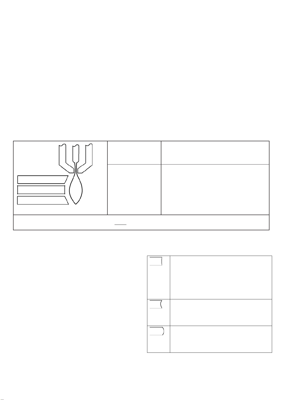
Ispezione dei ricambi consumabili
Ricambio Controllo Provvedimento
Rotondità del foro centrale.
Protezione
ugello
Accumulo di residui nello spazio tra
la protezione e l'ugello.
- L'angolo di taglio non è retto. Cause possibili:
• La direzione di spostamento della torcia è errata. Il taglio
di alta qualità si trova sempre sul lato destro rispetto al
movimento in avanti della torcia.
• La distanza tra la torcia e la lamiera non è corretta.
• La velocità di taglio non è corretta.
• I consumabili sono usurati e devono essere sostituiti.
- La vita utile dei consumabili è ridotta. Cause possibili:
• La corrente dell'arco, la tensione dell'arco, la velocità di
taglio e altre variabili non sono configurate come
specificato nelle tabelle di taglio.
• Innescare l'arco nell'aria (iniziare o finire il taglio fuori dalla
superficie della lamiera). È possibile iniziare dal bordo a
condizione che l'arco sia a contatto con la lamiera quando
innescato.
• Inizio di uno sfondamento con un'altezza torcia errata.
Se il foro non è più rotondo, sostituire la
protezione ugello.
Rimuovere la protezione ed eliminare qualsiasi
residuo.
Ugello
Elettrodo
Diffusore isolante
O-ring della
torcia
Rotondità del foro centrale.
o o
Buono
Usura della superficie centrale;
verifica della profondità del cratere.
Massimo 1,5 mm
Danni o usura sulla superficie interna
del diffusore; verificare che i fori del
gas non siano ostruiti.
Verificare che la superficie non sia
danneggiata, usurata o senza
lubrificazione.
Usurato
Se il foro centrale non è rotondo, sostituire sia
l'ugello che l'elettrodo.
Se la superficie è usurata o la profondità del
cratere è superiore a 1,5 mm sostituire sia l'ugello
che l'elettrodo.
Sostituire se la superficie è danneggiata o usurata
o se i fori del gas sono ostruiti.
Se l'o-ring è secco, lubrificarlo insieme alle
filettature con uno strato sottile di lubrificante
siliconico. Se l'o-ring presenta delle crepe o è
danneggiato, sostituirlo.
7

8
INSTRUCTIONS FOR PLASMA CUTTER
IMPORTANT
READ THIS MANUAL AND THE SAFETY RULES
MANUAL CAREFULLY BEFORE INSTALLING, USING,
OR SERVICING THE MACHINE, PAYING SPECIAL
ATTENTION TO SAFETY RULES. CONTACT YOUR
DISTRIBUTOR IF YOU DO NOT FULLY UNDERSTAND
THESE INSTRUCTIONS.
This machine must be used for cutting only.
It is also essential to pay special attention to the "SAFETY
RULES" Manual. The symbols next to certain paragraphs
indicate points requiring extra attention, practical advice or
simple information.
This MANUAL and the "SAFETY RULES" MANUAL must
be stored carefully in a pica familiar to everyone involved in
using the machine. They must be consulted whenever
doubts arise and be kept for the entire lifespan of the
machine; they will also be used for ordering replacement
parts.
1. INSTALLATION
1.1. TORCH ASSEMBLY
This machine is suitable to work only with a genuine
ELETTRO C.F. torch. We do not assume any
responsibility in case that a different kind of torch is
used.
Pneumatic:
Located on the torch inlet to prevent low air pressure.
The LED D (see pict.1) lights when tripped.
It means that the pressure has temporarily gone below 3.2
÷ 3.5 bar.
Electrical:
Located on the torch body, to prevent hazardous voltages
from occurring on the torch when, swirl ring, electrode or
nozzle holder are replaced;
Do not remove or short-circuit the safety devices.
Use only original spare parts.
Always replace any damaged parts of the machine
with original materials.
Do not run the machine without its housings. This
would be dangerous to the operator and anyone else
in the work area, and would prevent the machine from
being cooled properly.
1.4. EXPLANATION OF TECHNICAL SPECIFICATIONS
Insert the torch onto the fitting I (see pict. 1) using the
special tool supplied, firmly tightening the ring-nut to avoid
air leaks that could damage or interfere with smooth
operation of the torch.
Do not dent the current pin or bend the pegs of the torch
fitting. A dented pin may not disconnect, while a bent peg
does not allow proper insertion onto the fixed fitting I (pict.
1), thereby preventing the machine from working.
1.2. DESCRIPTION OF DEVICES ON THE MACHINE
(Pict. 1)
A) Mains power led.
B) Block LED; lights when hazardous conditions arise
(See 5.1.1)
C) Thermostat LED
D) Low air pressure LED
E) "SELF-RESTART PILOT" function LED
F) Push-button to activate and deactivate the "SELF-
RESTART PILOT" function.
G) Cutting current regulator knob
I) Torch fitting
J) Grounding clamp
K) Pressure regulator knob
L) Compressed air fitting (1/4" female gas thread)
M) Pressure gauge
N) Water trap
O) Mains power switch
P) Power cord
1.3. SAFETY DEVICES
This system comes equipped with the following safety
devices:
Overload cut-out:
To avoid overloads. It is evidenced by the LED C (see
pict.1) continuously on.
IEC 60974-1 .... The equipment is built according to these
IEC 60974-10 standards.
IEC 60974-7
Cl. A ................. Machine for professional and industrial use.
Three-phase static transformer-rectifier
frequency converter.
................. Down slope.
............ Suitable for plasma cutting.
TORCH TYPE . Type of torch that may be used with this
machine to form a safe system.
U0 .................... Secondary open-circuit voltage.
X ...................... Duty cycle percentage.
The duty cycle expresses the percentage of
10 minutes during which the welding
machine may run at a certain current I
voltage U
without overheating.
2
and
2
I2 ...................... Cutting current.
U
.................... Secondary conventional voltage with
2
welding current I2 . This voltage depends
on the distance between the contact tip an d
the workpiece.
If this distance increases, the cutting
voltage also increases and the duty cycle
X% may decrease.
.................... Rated supply voltage.
U
1

9
3~ 50/60Hz .... 50- or 60-Hz three-phase power supply
I1 Max .............. Max. absorbed current at the
corresponding current I2 and voltage U2
I
eff ............... This is the maximum value of the actual
1
current absorbed, considering the duty
cycle. This value usually corresponds to the
capacity of the fuse (delayed type) to be
used as a protection for the equipment.
IP23 ................ Protection rating for the housing. Grade 3
as the second digit means that this
equipment is suitable for use outdoors in
the rain.
................ Suitable for use in high-risk environme nts.
NOTES: The machine has also been designed for use in
environments with a pollution rating of 3. (See IEC 664).
1.5. START-UP
The machine must be installed by qua lified personnel. Al l
connections must be made in compliance with current
safety standards and full observance of safety regulations
(see CEI 26-23 - IEC TS 62081).
Connect the air supply to the fitting L (pict. 1).
If the air supply comes from a pressure regulator of a
compressor or centralized system, the regulator must be
set to an output pressure of no more than 8 bar (0.8 Mpa).
If the air supply comes from a compressed air cylinder, the
cylinder must be equipped with a pressure regulator.
Never connect a compressed air cylinder directly to the
regulator on the machine! The pressure could exceed
the capacity of the regulator, which might explode!
Connect the power cord P (pict. 1): the yellow-green cable
wire must be connected to an efficient grounding socket on
the system. The remaining wires must be connected to the
power supply line by means of a switch placed as close as
possible to the cutting area, to allow it to be shut off quickly
in case of emergency.
The capacity of the cut-out switch or fuses installed in
series with the switch must be equal to the current I
eff.
1
absorbed by the machine.
The absorbed current I
eff. may be determined by reading
1
the technical specifications shown on the machine under
the available supply voltage U
.
1
Any extension cords must be sized appropriately for the
absorbed current I
max.
1
2. USE (see pict. 1)
Make sure the trigger has not been pressed.
Turn the machine on using the switch O. The warning
lamp A will light to indicate that the machine is on.
Set the pressure shown by the pressure gauge M at 5 bar
(0,5 MPa) by means of the reducer knob K, and then lock
the knob by pushing it down. Connect the grounding clamp
to the workpiece.
The cutting circuit must not be deliberately placed in direct
or indirect contact with the protective wire except in the
workpiece.
If the workpiece is deliberately grounded using the
protective conductor, the connection must be as direct as
possible and use a wire of at least the same size as the
cutting current return wire, and connected to the workpiece
at the same point as the return wire using the return wire
clamp or a second grounding clamp placed in the
immediate vicinity. Every precaution must be taken to avoid
stray currents.
Use the knob G to select the cutting current.
Item 452: use a nozzle of diameter 0,95.
Item 454: use a nozzle of diameter 1,10.
Make sure that the grounding clamp and workpiece have a
good electrical contact, especially with painted, oxidized or
insulated sheet metal.
Do not connect the grounding clamp to the part of the
material that is to be removed.
Press the torch trigger to strike the pilot arc.
If cutting does not begin within 2 seconds, the pilot arc
goes out; press the trigger again to re-strike it.
Hold the torch upright while cutting.
When you have finished cutting and released the trigger,
air will continue to leave the torch for approximately 100
seconds to allow the torch to cool down.
It is advisable not to turn the machine off until this
cool-down period is complete.
Should you need to make holes or begin cutting from the
centre of the workpiece, you must hold the torch at an
angle and slowly straighten it so that the nozzle does not
spray molten metal (see pict. 2). This must be done when
making holes in pieces more than 3 mm thick.
During automatic operation, for piercing (see pict. 3), start
with a distance between the nozzle and the workpiece
greater than the distance of the cut.
For thicknesses greater than:
10 mm for art. 452
14 mm for art. 454
the material must be perforated before cutting.
When making circular cuts, we recommend using the
special compass available upon request. It is important to
remember that use of the compass may make it necessary
to use the starting technique described above (see pict. 2).
Do not keep the pilot arc lit in the air when not needed, to
avoid unnecessary consumption of the electrode, swirl ring
or nozzle.
Turn the machine off when the task is completed.
To cut perforated or grid metal, activate the special
function using the push-button F (LED E lit).
When you have finished cutting, holding this push-button
down will cause the pilot arc to restart automatically.
Use this function only if necessary to avoid unnecessary
wear on the electrode and nozzle.
3. CUTTING ERRORS
3.1. INSUFFICIENT PENETRATION
This error may be caused by the following:
high speed. Always make sure that the arc fully
penetrates the workpiece and is never held at a
forward angle of more than 10 - 15°. This will avoid
incorrect consumption of the nozzle and burns to the
nozzle holder.
Excessively thick workpiece.
Grounding clamp not in good electrical contact with
the workpiece.
Worn nozzle and electrode.
Cutting current too low.
NOTE: When the arc does not penetrate, the molten metal
scraps obstruct the nozzle.
3.2. THE CUTTING ARC GOES OFF
This error may be caused by:
• worn nozzle, electrode or swirl ring
• air pressure too high
• supply voltage too low
3.3. SLANTED CUT
If the cut appears slanted, turn the machine off and replace
the nozzle.
When the cutting current is above 45 A, prevent the nozzle

10
from coming into electrical contact with the workpiece
LED B
CONDITION
SOLUTION
Upon equipment startup
Incorrect IGBT drive
voltage
Contact technical
service
Reed contact closed
start-up
(even through scraps of molten metal), this condition
causes rapid and at times instantaneous destruction of the
nozzle hole, leading to poor quality cutting.
3.4. EXCESSIVE WEAR ON CONSUMABLE PARTS
This problem may be caused by:
a) air pressure too low compared to the recommended
level.
b) excessive burns on the end of the nozzle holder.
4. HELPFUL HINTS
25 should be replaced when its central hole is damaged or
enlarged in comparison with the new part.
The use of a worn electrode quickly wears out the nozzle.
When the electrode is worn, the power cut of the machine
is reduced. A delayed replacement of electrode and nozzle
causes overheating of consumable parts and reduces the
life of diffuser 24. Make sure that after replacing it, nozzle
holder 26 is tight enough.
ATTENTION! Nozzle holder 26 should be screwed on
head only when electrode 23, diffuser 24 and nozzle 25
are assembled.
If the system air contains considerable amounts of
moisture and oil, it is best to use a drying filter to avoid
excessive oxidation and wear on consumer parts,
damage to the torch and a reduction in the speed and
quality of the cutting.
The impurities in the air encourage oxidation of the
electrode and nozzle, and may make it difficult to
strike the pilot arc. If this occurs, use fine sandpaper
to clean the end of the electrode and the interior of the
nozzle.
Make sure that the new electrode and nozzle to be
mounted are thoroughly clean and degreased.
Always use original spare parts to avoid damaging
the torch.
5. MAINTENANCE
Always cut off the power supply to the machine before any
operation, which must always be carried out by qualified
personnel.
5.1. GENERATOR MAINTENANCE
In the case of maintenance inside the machine, make sure
that the switch O (pict. 1) is in position "O" and that the
power cord is disconnected from the mains.
Also make sure that there is no voltage at the ends of the
IGBT group capacitors.
Even though the machine is equipped with an automatic
condensation drainage device that is tripped each time the
air supply is closed, it is good practice to periodically make
sure that there is no condensation accumulated in the
water trap N (pict.1).
It is al so necessa ry to period ically clean the interior of the
machine from the accumulated metal dust, using
compressed air.
5.3. PRECAUTIONS AFTER REPAIRS
After making repairs, take care to organize the wiring so
that there is secure insulation between the primary and
secondary sides of the machine. Do not allow the wires to
come into contact with moving parts or those that heat up
during operation. Reassemble all clamps as they were on
the original machine, to prevent a connection from
occurring between the primary and secondary circuits
should a wire accidentally break or be disconnected.
Also mount the screws with geared washers as on the
original machine.
5.1.1 Troubleshooting
The LED B (pict. 1) lights when the following conditions
occur:
Steadily lit
Steadily lit
Steadily lit
5.2. TORCH MAINTENANCE (See pages 33,35,37 and 39)
Replacement of consumable parts
The parts subject to wear are electrode 23, diffuser 24 and
nozzle 25. All parts may be only replaced after loosening
nozzle holder 26. Electrode 23 should be replaced when a
1/16" (1,5 mm) deep crater is created in the middle. Nozzle
during equipment
Wait 5 sec
Contact technical
service

6. HOW TO USE THE MACHINE TORCH
6.2. Understand and optimize cut quality
The information in the following sections can help you to
optimize cut quality and maximize consumable parts life.
6.1. Ensure the torch and table are set up correctly
• Align the torch at a right angle to the workpiece.
• The torch may travel more smoothly if you clean, check, and
“tune” the rails and drive system on the cutting table. Unsteady
machine motion can cause a regular, wavy pattern on the cut
surface.
• Ensure that the torch does not touch the workpiece during
cutting. Contact with the workpiece can damage the shield and
nozzle and affect the cut surface.
Cause
Problem
Negative cut angle
The torch is too low. Raise the torch; or if you are using a torch
There are several factors to consider in cut quality:
1) Cut angle: the degree of angularity of the cut edge.
2) Dross: the molten material that solidifies on the top or
bottom of the workpiece.
3) Straightness of the cut surface: the cut surface can be
concave or convex.
The following sections explain how these factors can affect cut
quality.
1) Cut or bevel angle
• A positive cut angle results when more material is removed
from the top of the cut than from the bottom.
• A negative cut angle results when more material is removed
from the bottom of the cut.
Solution
height control, increase the arc voltage.
Cut OK
Positive cut angle
Notes: the right cut angle will be on the right
some degree of bevel.
2) Dross
Some amount of dross will always be present when cutting
with air plasma. However, you can minimize the amount and
type of dross by adjusting your system correctly for your
application.
Dross appears on the top edge of both pieces of the plate
when the torch is too low (or voltage is too high if using a torch
height control). Adjust the torch or the voltage in small
increments until the dross is reduced.
Low-speed dross forms when the torch’s cutting speed is too
slow and the arc shoots ahead. It forms as a heavy, bubbly
deposit at the bottom of the cut and can be removed easily.
Increase the speed to reduce this type of dross.
High-speed dross forms when the cutting speed is too fast and
the arc lags behind. It forms as a thin, linear bead of solid
metal attached very close to the cut. It is welded to the bottom
of the cut and is difficult to remove. To reduce high-speed
dross:
• Decrease the cutting speed.
• Decrease the torch-to-work distance.
The torch is too high Lower the torch; or if you are using a torch height
side with respect to the forward motion of the torch. The left side will always have
control, decrease the arc voltage.
3) Straightness of the cut surface
A typical plasma cut surface is slightly concave.
The cut surface may become more concave or
convex. Correct torch height is required to keep
the cut surface acceptably close to straight. Worn
consumables also affect the straightness of the
cut.
A strongly concave cut surface occurs when the
torch-to-work distance is too low. Increase the
torch-to-work distance to straighten the cut
surface.
A convex cut surface occurs when the torch-towork distance is too great or the cutting current is
too high. First, try lowering the torch, then reduce
the cutting current.
11

6.3. To pierce a workpiece using the machine torch
As with the hand torch, you can start a cut with the machine
torch at the edge of the workpiece or by piercing the
workpiece. Piercing will result in a shorter consumable life than
with edge starts.
making good contact or the table is not properly
grounded.
• The voltage is set too low.
• The cut speed is too high.
• The consumables are worn and need to be replaced.
• The metal being cut exceeds the maximum capacity.
The cut charts include a column for the height at which the
torch should be when starting a pierce and a column for the
delay of piercing.
- Dross forms on the bottom of the cut. Causes can be:
• The cutting speed is not correct.
• The voltage is set too low.
• The consumables are worn and need to be changed.
Notes: when piercing maximum thicknesses, the ring of dross
that forms during the pierce may become high enough to
contact the torch when the torch begins to move after the
pierce is complete.
- The cut angle is not right. Causes can be:
• The direction of the torch travel is incorrect. The high-
quality cut is always on the right with respect to the
forward motion of the torch.
6.4. Common machine-cutting faults
• The torch-to-work distance is not correct.
• The cutting speed is not correct.
- The torch pilot arc will initiate, but will not transfer. Causes
• The consumables are worn and need to be replaced.
can be:
• The work cables connection on the cutting table is not
making good contact or the table is not properly
grounded.
• The torch-to-work distance is too great.
- The consumable life is shortened. Causes can be:
• The arc current, arc voltage, cuting speed, and other
variables are not set as specified in the cut charts.
• Firing the arc in the air (beginning or ending the cut off of
the plate surface). Starting at the edge is acceptable as
- The workpiece is not totally penetrated, and there is
excessive sparking on the top of the workpiece. Causes
can be:
long as the arc makes contact with the workpiece when
started.
• Starting a pierce with an incorrect torch height.
• The work cable’s connection on the cutting table is not
Inspect the consumables
Consumable part Examine Action
The centre hole for roundness.
Shield cup
The space between the shield cup
and the nozzle for accumulated
debris.
If the hole is no longer round, replace the
shield.
Remove the shield cup and clean any material
away.
Nozzle
Electrode
Insulating diffusor
O-ring for torch
head
The centre hole for roundness.
o o
Good Worn
The centre surface for wear and verify
the pit depth
Max
imum 1.5 mm
The internal surface of the diffusor for
damage or wear and the gas holes for
obstructions.
The surface for damage, wear or a
lack of lubrication.
If the centre hole is not round, replace the nozzle
and the electrode together.
If the surface is worn or the pit depth is greater
than 1.5 mm deep, replace the nozzle and the
electrode together.
Replace if the internal surface is damaged or
worn or any of the gas holes are obstructed.
If the o-ring is dry, lubricate it and the threads with
a thin layer of silicone lubricant. If the o-ring is
cracked or worn, replace it.
12
BETRIEBSANLEITUNG FÜR PLASMASCHNE IDGERÄTE
WICHTIG:
VOR INSTALLATION UND GEBRAUCH DIESER MASCHINE
BZW. VOR AUSFÜHRUNG VON BELIEBIGEN
WARTUNGSARBEITEN, DIESES HANDBUCH UND DAS
HANDBUCH “SICHERHEITSVORSCHRIFTEN FÜR DEN
GERÄTEGEBRAUCH” AUFMERKSAM LESEN. DABEI IST
DEN SICHERHEITSNORMEN BESONDERE BEACHTUNG
ZU SCHENKEN. BITTE WENDEN SIE SICH AN IHREN
GROSSHÄNDLER, WENN IHNEN AN DIESER ANLEITUNG
ETWAS UNKLAR IST.
Diese Maschine darf nur zur Ausführung von Schneidarbeiten
verwendet werden.
Des Weiteren ist dem Handbuch, das die
Sicherheitsvorschriften enthält, größte Beachtung zu
schenken. Die Symbole neben den einzelnen Paragraphen
weisen auf Situationen, die größte Aufmerksamkeit verlangen,
Tipps oder einfache Informationen hin. Die beiden Handbücher
sind sorgfältig an einem Ort aufzubewahren, der allen
Personen, die mit dem Gerät zu tun haben, bekannt ist. Sie
sind immer dann heranzuziehen, wenn Zweifel bestehen. Die
beiden Handbücher haben die Maschine über ihre ganze
Lebensdauer zu “begleiten” und sind bei der Bestellung von
Ersatzteilen heranzuziehen.
1. INSTALLATION
1.1. MONTAGE DES BRENNERS
Diese Anlage ist fähig nur für Brenner Typ ELETTRO C.F..
Wir werden irgendeine Verantwortung bezüglich der
Verwendung von verschiedenen Brenner ablehnen.
Den Brenner in Anschluss I (Abb. 1) stecken mit dem
Spezialwerkzeug und den Gewindering bis zum Anschlag
anziehen, um das Austreten von Luft zu verhindern, da
hierdurch der Brenner beschädigt und sein Betrieb
beeinträchtigt werden könnte.
Darauf achten, den Stromführenden Zapfen nicht zu verbeulen
und die Stifte des Brenneranschlusses nicht zu verbiegen.
Wenn der Zapfen verbeult ist, lässt er sich nicht mehr lösen,
und wenn die Stifte verbogen sind, ist nicht mehr
gewährleistet, dass der Brenneranschluss ordnungsgemäß in
den festen Anschluss I (Abb. 1) eingesteckt werden kann, was
zu Fehlfunktionen des Ger äts f ühren kan n.
Thermischer Schutz:
Zur Vermeidung von Überlastung. Meldung durch
ständiges Leuchten der LED C (siehe Abb. 1).
Druckschalter:
Er befindet sich auf der Brennerspeisung und spricht
bei zu geringem Luftdruck an. Meldung durch Aufleuchten der
LED D (siehe Abb. 1). Dies bedeutet, dass der Druck
vorübergehend unter 3,2 - 3,5 bar gesunken ist.
Elektrischer Schutz:
Er befindet sich auf dem Brennerkörper und verhindert, dass
während des Austausches der Düse, des Diffusors, der
Elektrode und der Düsenspannhülse gefährliche Spannungen
am Brenner anliegen.
Niemals die Sicherheitsvorrichtungen entfernen oder
überbrücken.
Nur Originalersatzteile verwenden.
Eventuell beschädigte Teile der Maschine oder des
Brenners nur durch Originalersatzteile ersetzen.
Die Maschine nicht ohne Schutzabdeckung in Betrieb
nehmen.
Hierdurch würden sowohl der Bediener als auch die Personen,
die sich im Arbeitsbereich aufhalten, gefährden. Außerdem
wird hierdurch die angemessene Kühlung des Geräts
verhindert.
1.4. ERLÄUTERUNG DER TECH NISCHEN DATEN
1.2. BESCHREIBUNG DER VORRICHTUNGEN DES
GERÄTS (Abb. 1)
A) Netzkontrollampe.
B) Anzeige-LED der Sicherheitsverriegelung; sie leuchtet
auf, wenn gefährliche Arbeitsbedingungen vorliegen
(siehe Abschnitt 5.1.1).
C) LED Thermostat
D) LED "Luftdruck ungenügend"
E) LED, die aufleuchtet, wenn die Funktion "SELF-
RESTART PILOT" aktiviert ist.
F) Taster zum Ein- und Ausschalten der Funktion "SELF-
RESTART PILOT".
G) Drehknopf zum Regeln des Schneidstroms
I) Anschluss für Brenner
J) Masseklemme
K) Drehknopf zum Regeln des Drucks
L) Druckluftanschluss (Innengewinde 1/4 Zoll)
M) Manometer
N) Kondenswasserbehälter
O) Netzschalter
P) Elektrische Zule itung
1.3. SICHERHEITSVORRICHTUNGEN
Diese Anlage verfügt über folgende Sicherheitsvorrichtungen:
IEC 60974.1........ Die Konstruktion des Geräts entspricht
IEC 60974-10 diesen europäischen Normen.
IEC 60974-7
Cl. A .................... Maschine für den industriellen und den
professionellen Einsatz.
.. Statischer Dreiphasen-Frequenzumrichter
Transformator-Gleichrichter.
.................... Fallende Kennlinie.
............... Geeignet zum Plasmaschneiden.
TORCH TYPE .... Brennertyp, der mit diesem Gerät verwendet
werden muss, damit die Sicherheit des
Systems gewährleistet ist.
U0 ....................... Leerlauf-Sekundärspannung.
X ......................... Einschaltdauer.
Die relative Einschaltdauer ist der auf eine
Spieldauer von 10 Minuten bezogene
Prozentsatz der Zeit, die das Gerät bei einer
13

bestimmten Stromstärke I2 und einer
Spannung U2 arbeiten kann, ohne sich zu
überhitzen.
......................... Schneidstrom.
I
2
U
....................... Konventionelle Sekundärspannung bei
2
Schneidstrom I2. Diese Spannung ist
abhängig vom Abstand zwischen Düse und
Werk stück. Vergrößert sich dieser Abstand,
erhöht sich auch die Schneidspannung, was
eine Verringerung der relativen
Einschaltdauer X% mit sich bringen kan n.
....................... Bemessungsspeisespannung.
U
1
3~ 50/60 Hz ........ Dreiphasenspeisung 50 oder 60 Hz.
I1 Max ................. Maximale Stromaufnahme bei
entsprechendem Strom I
und Spannung U2.
2
I1 eff ................... Dies ist der Höchstwert der effektiven
Stromaufnahme bei Berücksichtigung der
relativen Einschaltdauer.
Normalerweise entspricht dieser Wert dem
Bemessungsstrom der Sicherung (träge), die
zum Schutz des Geräts zu verwenden ist.
IP23 .................... Schutzart des Gehäuses. Die zweite Ziffer 3
gibt an, dass dieses Gerät im Freien bei
Regen betrieben werden darf.
................... Geeignet zum Betrieb in Umgebungen mit
erhöhter Gefährdung.
HINWEIS: Das Gerät ist außerdem für den Betrieb in
Umgebungen mit Verunreinigungsgrad 3 konzipiert. (Siehe
IEC 664).
1.5. EINRICHTEN
Die Installation des Geräts muss von Fachpersonal ausgeführt
werden. Alle Anschlüsse müssen in Übereinstimmung m it den
geltenden Bestimmungen und unter strikter Beachtung der
Unfallverhütungsvorschriften ausgeführt werden (siehe CEI 2623 IEC - TS 62081).
Die Druckluftspeisung an Anschluss L (Abb. 1) anschließen.
Kommt die Druckluftspeisung vom Druckminderer eines
Verdichters oder einer zentralen Druckluftanlage, muss der
Druckminderer auf einen maximalen Auslassdruck von 8 bar
(0,8 MPa) eingestellt werden. Kommt die Druckluft von einem
Druckluftbehälter, muss dieser mit einem Druckregler
ausgestattet sein.
Niemals einen Druckluftbehälter direkt an den
Druckminderer des Geräts anschließen! Der Druck könnte
die Belastbarkeit des Druckminderers überschreiten und
folglich dazu führen, dass der Druckminderer explodiert!
Die elektrische Zuleitung P (Abb. 1) anschließen: der gelbgrüne Schutzleiter muss an eine wirksame Erdungsanlage
angeschlossen werden; die übrigen Leiter über einen Schalter
ans Netz anschließen; der Schalter sollte sich möglichst in der
Nähe des Schneidbereichs befinden, um die unverzügliche
Ausschaltung im Notfall zu gestatten.
Der Bemessungsstrom des thermomagnetischen Schalters
oder der in Reihe mit dem Schalter geschalteten Sicherungen
muss gleich dem vom Gerät aufgenommenen Strom I
eff.
1
sein.
Die Stromaufnahme I
eff. kann aus den technischen Daten für
1
die Speisespannung U1 abgeleitet werden, die auf dem Gerät
angegeben sind. Möglicherweise verwendete Verlängerungen
müssen einen der Stromaufnahme I
max. angemessenen
1
Querschnitt haben.
2. BETRIEB (Abb. 1)
Sicherstellen, dass der Start-Taster nicht gedrückt ist.
Das Gerät mit Schalter O einschalten. Dieser Vorgang
wird durch Aufleuchten der Kontrolllampe A angezeigt.
Mit dem Einstellhandgriff K des Druckminderers den auf
Manometer M angezeigten Druck auf 5 bar (0,5 MPa)
einstellen und dann den Einstellhandgriff nach unten drücken,
um ihn zu verriegeln.
Die Masseklemme an das Werkstück anschließen.
Der Schneidstromkreis darf nicht absichtlich in direkten oder
indirekten Kontakt mit dem Schutzleiter gebracht werden,
sofern dies nicht über das Werkstück selbst geschieht.
Wenn das W erkstück a bsichtlic h über den S chutzlei ter mit der
Erde verbunden wird, muss diese Verbindung so direkt wie
möglich gestaltet werden. Der hierzu verwendete Leiter muss
einen Querschnitt aufweisen, der mindestens gleich dem
Querschnitt der Schneidstromrückleitung ist, und an der
gleichen Stelle an das Werkstück angeschlossen werden wie
die Rückleitung.
Hierzu entweder die Rückleitungsklemme oder eine
unmittelbar daneben angeordnete zweite Werkstückklemme
verwenden. Es ist jede Vorsichtsmaßnahme zu ergreifen, um
Kriechströme zu vermeiden.
Mit dem Drehknopf G den Schneidstrom einstellen.
Für Art. 452: eine Düse mit einem Durchmesser von 0,95
verwenden.
Für Art. 454: eine Düse mit einem Durchmesser von 1,10
verwenden.
Sicherstellen, dass die Masseklemme und das Werkstück
einen guten elektrischen Kontakt haben; dies gilt insbesondere
bei lackierten oder oxidierten Blechen und bei Blechen mit
einer isolierenden Beschichtun g.
Die Masseklemme nicht an dem Teil des Werkstücks
befestigen, das abgetrennt werden soll .
Den Brennertaster drücken, um den Pilotlichtbogen zu zünden.
Wenn man nicht innerhalb von 2 Sekunden zu schneiden
beginnt, erlischt der Pilotlichtbogen und muss daher ggf. durch
erneute Betätigung des Brennertasters wieder gezündet
werden. Den Brenner während des Schnitts senkrecht halten.
Wenn man nach Abschluss des Schnitts den Brennertaster
löst, tritt weiterhin für die Dauer von rund 100 Sekunden Luft
aus dem Brenner aus, die zur Kühlung des Brenners dient.
Es ist ratsam, das Gerät nicht vor Ablauf dieser Zeit
auszuschalten.
Wenn man Löcher ausschneiden möchte oder den Schnitt in
der Mitte des Werkstücks beginnen muss, dann muss man den
Brenner zuerst geneigt halten und dann langsam aufrichten,
damit das geschmolzene Metall nicht auf die Düse spritzt
(siehe Abb. 2). In dieser Weise ist zu verfahren, wenn in
Bleche von mehr als 3 mm Dicke Löcher geschnitten werden
sollen.
Beim Maschinenschneiden, zum Durchdringen (siehe Abb. 3)
beginnen mit einem Abstand zwischen der Düse und dem
Werkstück größer als der Abstand des Schnitts.
Bei Dicken über:
10 mm für Art. 452
14 mm für Art. 454
muss das Material vor dem Schneiden perforiert werden. Zum
Ausführen von kreisrunden Schnitten empfiehlt sich die
Verwendung des auf Wunsch lieferbaren Zir k el s.
Man sollte stets daran denken, dass man bei Gebrauch des
Zirkels möglicherweise bei Beginn des Schnitts wie oben
beschrieben verfahren muss (siehe Abb. 2).
Den Lichtbogen nicht unnötig brennen lassen, da sich
hierdurch der Verschleiß der Elektrode, des Diffusors und der
Düse erhöht.
Nach Abschluss der Arbeit das Gerät ausschalten.
Zum Schneiden von Lochblechen oder Gittern die
besondere Funktion mit Taster F einschalten (LED E leuchtet).
Nach Abschluss des Schneidvorgangs wird der
Pilotlichtbogen, wenn man den Taster gedrückt hält,
automatisch wieder gezündet.
Diese Funktion nur im Bedarfsfall verwenden, um eine
unnötige Abnutzung der Elektrode und der Düse zu
vermeiden.
14
 Loading...