

Elettro CF 492, Plasma Series, 494, 496 Spare Parts
I MANUALE DI ISTRUZIONI PER APPARECCHI TAGLIO PLASMA Pag. 4
GB INSTRUCTIONS FOR PLASMA CUTTERS Pag. 9
D BETRIEBSANLEITUNG FÜR PLASMASCHNEIDGERÄTE Seite 14
F MANUEL D'INSTRUCTIONS POUR APPAREIL DE DÉCOUPE Pag. 19
E MANUAL DE INSTRUCCIONES PARA EQUIPO DE CORTE EN PLASMA Pag. 24
P MANUAL DE INSTRUÇÃO PARA APARELHO DE CORTE AO PLASMA Pag. 29
Parti di ricambio e schema elettrico
Spare parts and wiring diagram
Ersatzteile und elektrischer Schaltplan
Pièces de rechanges et schéma électrique
Partes de repuesto y esquema eléctrico
Peças e esquema eléctrico Pagg. Seiten 34

2
3
MANUALE DI ISTRUZIONI PER APPARECCHIO DI TAGLIO AL PLASMA
Importante!!!
Prima dell'installazione, dell'uso o di qualsiasi
manutenzione alle macchine, leggere attentamente il
contenuto del libretto "Regole di sicurezza per l'uso delle
apparecchiature" e del "Manuale di istruzioni" specifico
per ogni macchina.
Contattate il vostro distributore se non avete compreso
completamente le istruzioni.
1 DISPOSITIVI DI SICUREZZA
Questo impianto è provvisto delle seguenti sicurezze:
Termica:
Per evitare eventuali sovraccarichi, ed
evidenziata dall'accensione della lampada spia C (vedi
fig.1).
Pneumatica:
Per evitare che la pressione aria sia
insufficiente, posta sull'alimentazione della torcia
evidenziata dalla spia E (vedi fig. 1).
Elettrica:
1) Posta sul corpo torcia per evitare che vi siano tensioni
pericolose sulla torcia quando si sostituiscono l'ugello, il
diffusore, l'elettrodo o il portaugello;
2) Che manda in blocco la macchina quando l'elettrodo
raggiunge uno stato di usura tale da dover essere
sostituito. Questa seconda funzione è evidenziata
dall'accensione della lampada P (escluso il modello 494)
(fig. 1).
3) Posta sul pannello della macchina per evitare che vi
siano tensioni pericolose sulla torcia durante la
sostituzione della torcia stessa.
Non eliminare o cortocircuitare le sicurezze.
−
Utilizzare solamente ricambi originali.
−
Sostituire sempre con materiale originale
−
eventuali parti danneggiate della macchina o della
torcia.
Non utilizzare una torcia diversa da quella
−
originale.
Non far funzionare la macchina senza i coperchi.
−
Questo sarebbe pericoloso per l'operatore e le
persone che si trovano nell'area di lavoro ed
impedirebbe alla macchina un raffreddamento
adeguato.
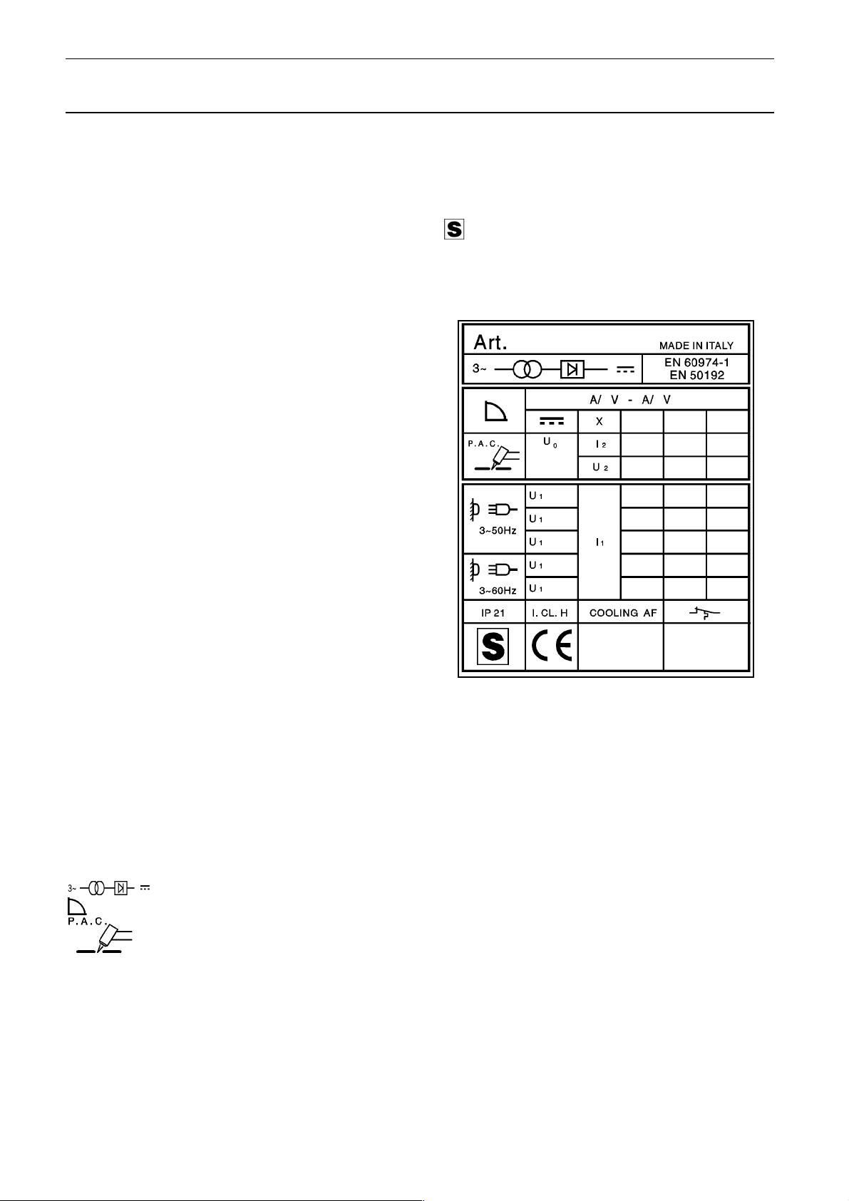
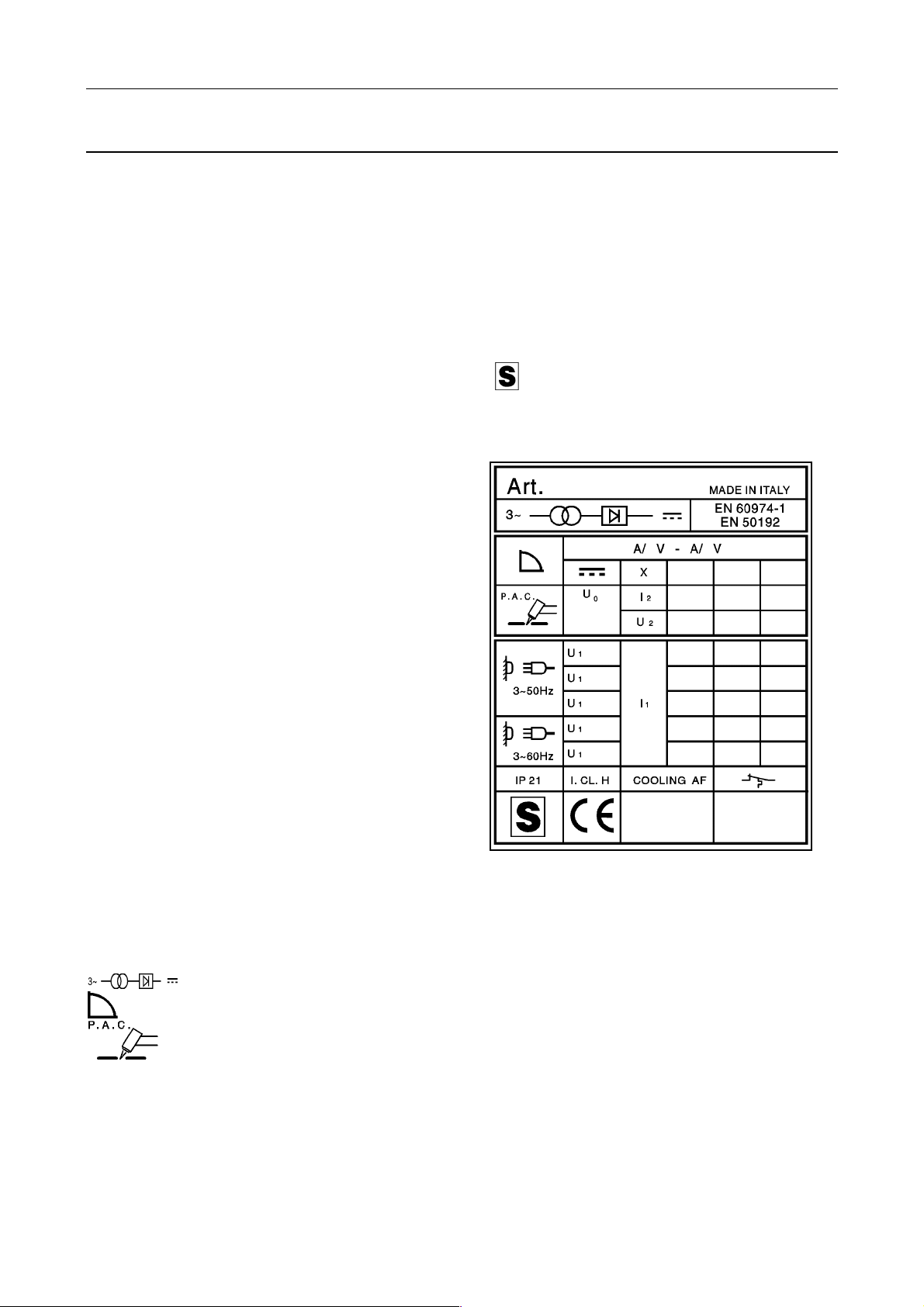
2 SPIEGAZIONE DEI DATI TECNICI
IEC974-1........ L'apparecchio è costruito secondo
EN60974-1 queste norme internazionali.
Art. ............... Articolo della macchina che deve essere
sempre citato assieme al nr. di matricola
per qualsiasi richiesta relativa alla
saldatrice.
. Trasformatore raddrizzatore trifase.
................ Caratteristica discendente.
..... Adatto per taglio al plasma.
Uo ................ Tensione a vuoto secondaria.
X .................. Fattore di servizio percentuale. Il fattore di
servizio esprime la percentuale di 10
minuti in cui il plasma può lavorare ad
una determinata corrente senza causare
surriscaldamenti.
I
................... Corrente di taglio.
2
U
.................. Tensione secondaria con corrente di
2
U
.................. Tensione nominale di alimentazione.
1
taglio I
.
2
3~50/60Hz ..... Alimentazione trifase 50 oppure 60Hz.
I1................... Corrente assorbita alla corrispondente
corrente di taglio I
.
2
IP 21 ............. Grado di protezione della carcassa.
Grado 1 come seconda cifra significa che
questo apparecchio non è idoneo a
lavorare all'esterno sotto la pioggia.
.............. Idonea a lavorare in ambienti con rischio
accresciuto.
NOTE: L'apparecchio è inoltre stata progettata per
lavorare in ambienti con grado di inquinamento 3. (Vedi
IEC 664).
3 DESCRIZIONE DISPOSITIVI SULLA MACCHINA
(Vedi
fig.1 e fig.2)
A) Interruttore di rete.
B) Lampada spia di rete.
C) Lampada spia termostato.
D) Manometro.
E) Lampada spia pressione aria insufficiente.
G) Innesto Texas.
H) Manopola di regolazione della corrente di taglio.
I) Riduttore di pressione aria.
L) Cavo di alimentazione.
M) Pressacavo.
P) Lampada spia elettrodo esaurito.
R) Adattatore fisso torcia.
S) Presa di alimentazione gruppo di raffreddamento.
T) Presa pressostato.
U) Fusibile.
3.1 Assemblaggio e disposizione
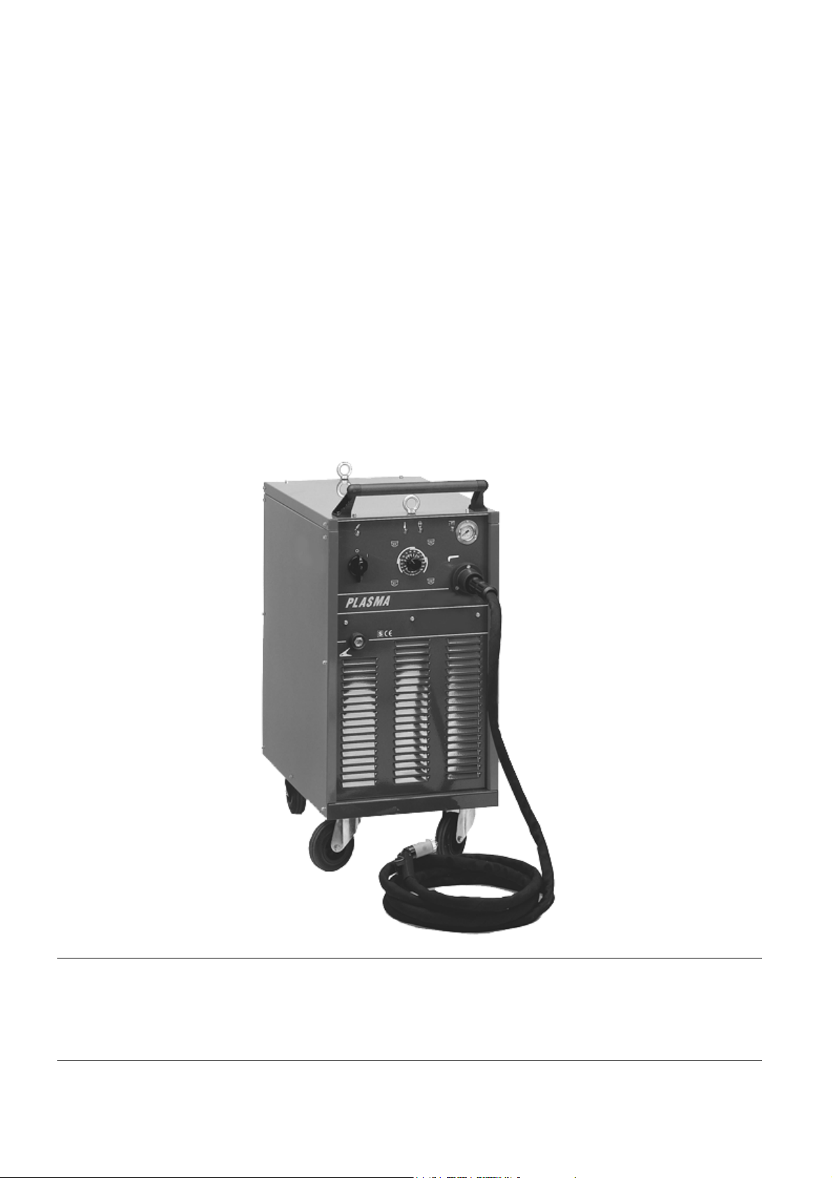
Togliere la macchina dall'imballo e montare il manico
utilizzando la chiave a brugola in dotazione. Disporre
l'apparecchio in un locale adeguatamente ventilato
possibilmente non polveroso, facendo attenzione a non
ostruire l'entrata e l'uscita dell'aria dalle asole di
raffreddamento. Montare la torcia (fig.3) sulla macchina
nel seguente modo:
1) Svitare le viti M6x16 poste nel pannello anteriore.
Infilare la flangia 1 nella torcia 2 ed avvitare la torcia
nell'adattatore 3. Inserire la flangia posizionando l'inserto
4

con molla nel foro corrispondente nel pannello della
macchina. Bloccare la flangia con le viti M6x16 nei fori
con inserti filettati.
2) Per la sostituzione della torcia svitare le viti M6x16,
togliere la flangia 1 svitare la torcia 2 dall'adattatore 3.
Per il montaggio della nuova torcia seguire le istruzioni al
punto 1. Fare molta attenzione a non ammaccare il perno
portacorrente o a non piegare gli spinotti dell'adattatore;
un'ammaccatura sul perno impedisce di scollegarlo, una
volta montato, dal raccordo fisso R (fig. 1); uno spinotto
piegato impedisce un buon fissaggio dell'adattatore sul
raccordo fisso R (fig. 1) ed impedisce alla macchina di
funzionare.
Questi impianti sono idonei solo per torce
ELETTRO CF tipo P150 (e, solo l'Art. 496, per torce
P50) sia manuali, sia automatiche e si declina ogni
responsabilità se utilizzati con torce di tipo diverso.
Non sollevare mai la macchina dal manico, ma
sempre dalle golfare in dotazione alla macchina.
3.2 Messa in opera
L'installazione della macchina deve essere fatta da
personale qualificato. Tutti i collegamenti devono
essere eseguiti in conformità delle vigenti norme e
nel pieno rispetto della legge antinfortunistica.
Collegare l'alimentazione dell'aria al raccordo posto sul
riduttore di pressione I (fig.2) assicurandosi che la
pressione sia almeno di 6 bar (6KPa X100) con una
portata minima di 200 litri/min. Nel caso che
l'alimentazione dell'aria provenga da un riduttore di
pressione di un compressore o di un impianto
centralizzato il riduttore deve essere regolato alla
massima pressione di uscita che non deve comunque
superare 8 bar (8KPaX100). Se l'alimentazione dell'aria
proviene da una bombola di aria compressa questa deve
essere equipaggiata con un regolatore di pressione;
non
collegare mai una bombola di aria compressa
direttamente al riduttore della macchina! La pressione
potrebbe superare la capacità del riduttore che quindi
potrebbe esplodere!
Assicurarsi che la tensione di
alimentazione corrisponda a quella indicata sulla targa
dati tecnici. Collegare il cavo di alimentazione L (fig.2): il
conduttore giallo verde del cavo deve essere collegato ad
un'efficiente presa di terra dell'impianto; i rimanenti
conduttori debbono essere collegati alla linea di
alimentazione attraverso un interruttore posto,
possibilmente, vicino alla zona di taglio per permettere
uno spegnimento veloce in caso di emergenza. La portata
dell'interruttore magnetotermico o dei fusibili in serie
all'interruttore deve essere uguale o superiore alla
corrente I
assorbita dalla macchina. La corrente I1,
1
assorbita si deduce dalla lettura dei dati tecnici riportati
sulla macchina in corrispondenza della tensione di
alimentazione U
debbono essere di sezione adeguata alla corrente I
, a disposizione. Eventuali prolunghe
1
,
1
assorbita.
3.3 Impiego
Accendere l'apparecchio mediante la manopola A (fig.1).
Questa operazione sarà evidenziata dall'accensione della
lampada B (fig.1). Premendo per un istante il pulsante
della torcia si comanda l'apertura del flusso dell'aria
compressa. Verificare che, in questa condizione, la
pressione indicata dal manometro D (fig. 1) sia fra 4,5 ÷
4,7 bar (4,5 ÷ 4,7 KPaX100); in caso contrario aggiustarla
agendo sulla manopola del riduttore I (fig. 2) quindi
bloccare detta manopola premendo verso il basso.
Collegare il morsetto di massa al pezzo da tagliare.
Scegliere, mediante la manopola H (fig. 1) la corrente di
taglio.
A)
Versione 90A.
Alluminio: fino 6 mm posizione 60A;
fino 16 mm posizione 90A.
Acciaio inossidabile e acciaio dolce:
fino 8/10 mm posizione 60A;
fino 20/22 mm posizione 90A.
N.B. In posizione 60A e 90A utilizzare ugelli D. 1,3.
B)
Versione 120A.
Alluminio: fino 4 mm posizione 50A;
fino 10/12 mm posizione 80A;
fino 20/22 mm posizione 120A.
Acciaio inossidabile e acciaio dolce:
fino 6 mm posizione 50A;
fino 15 mm posizione 80A;
fino 30 mm posizione 120A.
N.B. Utilizzare in posizione: 50A e 80A ugello D. 1,3;
120A ugello D. 1,6.
C)
Versione 150A.
Alluminio: fino 3/4 mm posizione 40/50A;
fino 8/10 mm posizione 80/90A;
fino 15/18 mm posizione 110/120A;
fino 22/25 mm posizione 150A.
Acciaio inossidabile e acciaio dolce:
fino 5 mm posizione 40/50A;
fino 12 mm posizione 80/90A;
fino 25 mm posizione 110/120A;
fino 35 mm posizione 150A.
La macchina è dotata di regolazione continua della
corrente di taglio, per cui l'utilizzatore può ricercare il
corretto valore in funzione delle condizioni di taglio. Il
diametro del foro dell'ugello della torcia è in funzione della
corrente di taglio e, così come è anche indicato sul
pannello frontale della macchina, deve essere:
Con 20/50A Ugello D. 1,1 mm;
40/90A Ugello D. 1,3 mm;
80/130A Ugello D. 1,6 mm;
120/150A Ugello D. 1,8 mm.
N.B. La qualità del taglio è notevolmente superiore se
si tiene l'ugello distante circa 2 mm dal pezzo. Per
ragioni pratiche, a volte, si preferisce tagliare con
l'ugello a contatto. Questa tecnica operativa non deve
essere usata con correnti superiori a 50A, perché
porta ad una rapida (a volte istantanea) distruzione
del foro dell’ugello e ciò provoca un taglio di pessima
qualità.
Assicurarsi che il morsetto e il pezzo siano in buon
contatto elettrico in particolare con lamiere verniciate,
ossidate o con rivestimenti isolanti. Non collegare il
morsetto di massa al pezzo di materiale che deve essere
asportato. Premere il pulsante della torcia per accendere
l'arco pilota. Se dopo 4 secondi non si inizia il taglio,
l'arco pilota si spegne e quindi, per riaccenderlo, è
necessario premere nuovamente il pulsante. Quando è
possibile la torcia deve essere tirata. Tirare è più facile
che spingere. Tenere la torcia verticale durante il taglio.
Completato il taglio e dopo aver lasciato il pulsante, l'aria
continua ad uscire dalla torcia per circa 1 minuto per
consentire alla torcia stessa di raffreddarsi. E' bene non
spegnere l'apparecchio prima della fine di questo tempo.
Nel caso si debbano eseguire fori o si debba iniziare il
taglio dal centro del pezzo si deve disporre la torcia in
posizione inclinata e lentamente raddrizzarla in modo che
il metallo fuso non sia spruzzato sull'ugello (vedi fig. 4).
Questa operazione deve essere eseguita quando si
lavorano pezzi di spessore superiore ai 3 mm. Nel caso si
debbano eseguire tagli in corrispondenza di angoli o di
rientranze (fig. 5) si consiglia di utilizzare elettrodi ed
ugelli prolungati. Nel caso si debbano eseguire tagli
circolari si consiglia di utilizzare l'apposito compasso
(fornito a richiesta). N.B. : Evitare di tenere inutilmente
acceso l'arco pilota in aria per non aumentare il consumo
dell'elettrodo, del diffusore e dell'ugello.
5

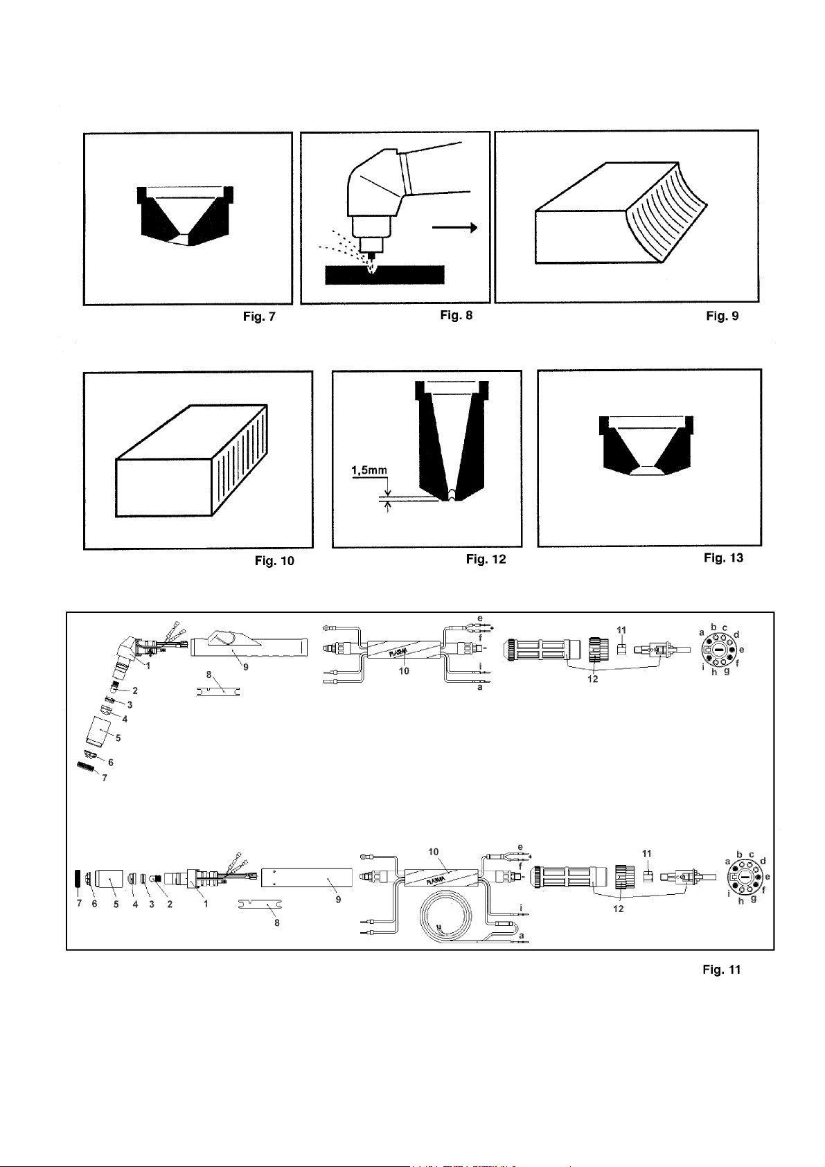
3.4 Inconvenienti di taglio
1) Insufficiente penetrazione.
Le cause di questo
inconveniente possono essere:
Velocità elevata. Assicurarsi sempre che l'arco sfondi
−
completamente il pezzo da tagliare e che non abbia mai
un'inclinazione, nel senso di avanzamento, superiore ai
10 - 15° (vedi fig. 6). Si eviteranno un consumo non
corretto dell'ugello (vedi fig. 7) e bruciature al portaugello
(vedi fig. 8).
Spessore eccessivo del pezzo (vedere diagramma
−
velocità di taglio e spessori).
Morsetto di massa non in buon contatto elettrico con il
−
pezzo.
Ugello ed elettrodo consumati.
−
Corrente di taglio troppo bassa.
−
N.B. : Quando l'arco non sfonda, le scorie di metallo fuso
ostruiscono l'ugello.
2) L'arco di taglio si spegne.
Le cause di questo
inconveniente possono essere:
Ugello, elettrodo o diffusore consumati.
−
Pressione aria troppo alta.
−
Tensione di alimentazione troppo bassa.
−
3) Taglio inclinato.
Qualora il taglio si presentasse
inclinato (vedi fig. 9) spegnere la macchina allentare il
portaugello e ruotare l'ugello di circa un quarto di giro,
quindi bloccare e riprovare. Ripetere l'operazione finché il
taglio non sia diritto (vedi fig. 10).
4) Eccessiva usura dei particolari di consumo.
Le
cause del sopraindicato problema possono essere:
a) Pressione aria troppo bassa rispetto a quella
consigliata.
b) Eccessive bruciature sulla parte terminale del
portaugello.
3.5 Consigli pratici
Se l'aria dell'impianto contiene umidità ed olio in
−
quantità notevole è bene utilizzare un filtro essiccatore
per evitare un'eccessiva ossidazione ed usura delle parti
di consumo, di danneggiare la torcia e che vengano
ridotte la velocità e la qualità del taglio.
Le impurità presenti nell'aria favoriscono l'ossidazione
−
dell'elettrodo e dell'ugello e possono rendere difficoltosa
l'accensione dell'arco pilota. Se si verifica questa
condizione pulire la parte terminale dell'elettrodo e
l'interno dell'ugello con carta abrasiva fine.
Assicurarsi che l'elettrodo e l'ugello nuovi che stanno
−
per essere montati siano ben puliti e sgrassati.
Per evitare di danneggiare la torcia utilizzare
−
sempre ricambi originali.
3.6 Scriccatura
(Solo ver. 494-496)
Questa operazione permette di togliere saldature
difettose, dividere pezzi saldati, preparare lembi ecc. e
viene usata quasi esclusivamente con la torcia manuale.
Per questa operazione si deve usare l'ugello D. 3 mm e si
deve montare il distanziale sulla boccola portaugello. Il
distanziale serve per evitare che il metallo fuso, durante
l'operazione di scriccatura bruci l'isolamento della boccola
portaugello. La corrente da utilizzare è: da 80A a
150A.L'operazione deve essere eseguita tenendo la
torcia inclinata e con il senso di avanzamento verso il
materiale fuso in modo che l'aria compressa che esce
dalla torcia lo allontani. L'inclinazione della torcia rispetto
al pezzo dipende dalla penetrazione che si vuole
ottenere. Poiché le scorie fuse durante il procedimento
tendono ad attaccarsi al distanziale e all'ugello, è bene
pulirli frequentemente per evitare che si inneschino
fenomeni tali (doppio arco) da distruggere l'ugello in pochi
secondi. Data la forte emissione di radiazioni infrarosse
ed ultraviolette durante questo procedimento si consiglia
una protezione molto accurata dell'operatore e delle
persone che si trovano nelle vicinanze durante
6
l'operazione.
3.7 Manutenzione torcia
Togliere sempre l'alimentazione alla macchina prima
di ogni intervento sulla torcia.
1) Sostituzione delle parti di consumo
(fig. 11). I
particolari soggetti ad usura sono l'elettrodo 2, il diffusore
3
e l'ugello 4. La sostituzione di una di queste parti è
possibile solo dopo avere svitato il portaugello 5.
L'elettrodo 2 deve essere sostituito quando presenta un
cratere al centro profondo circa mm. 1,5 (vedi fig. 12).
ATTENZIONE! Per svitare l'elettrodo non esercitare
sforzi improvvisi ma applicare una forza progressiva
fino a provocare lo sbloccaggio del filetto. Lubrificare
il filetto dell'elettrodo nuovo con lubrificante al
silicone (in dotazione alla macchina). L'elettrodo
nuovo deve essere avvitato nella sede e bloccato
senza stringere a fondo.
L'ugello 4 va sostituito quando
presenta il foro centrale rovinato oppure molto allargato
rispetto a quello del particolare nuovo (fig.13). Quando
l'elettrodo è consumato l'ugello si usura molto
rapidamente. Quando l'elettrodo è usurato la macchina
perde potenza di taglio. Una ritardata sostituzione
dell'elettrodo e dell'ugello provoca un eccessivo
riscaldamento delle parti, tale da pregiudicare la durata
del diffusore 3. Assicurarsi che dopo la sostituzione il
portaugello 5 sia stretto a sufficienza.
ATTENZIONE ! Il portaugello 5 deve essere avvitato
sulla testina solo con l'elettrodo 2 il diffusore 3 e
l'ugello 4 montati.
2) Sostituzione del corpo torcia 1
(vedi fig. 11).
Togliere la vite. Sfilare dal corpo 1 l'impugnatura
facendo oscillare l'impugnatura stessa e ponendo molta
attenzione a non strappare i fili del pulsante al momento
della separazione dei due particolari. Sfilare i conduttori
dei contatti di sicurezza. Sfilare la connessione. Svitare il
raccordo dopo aver tagliato il tubetto isolante. Montare il
nuovo corpo torcia eseguendo a ritroso tutte le operazioni
precedenti. L'isolamento del raccordo è ottenuto facendo
aderire al raccordo stesso il tubetto termorestringente
isolante riscaldandolo mediante una piccola sorgente di
calore (es.: un accendino). Prima di infilare l'impugnatura
assicurarsi che i cavi siano ben distanti fra di loro e che le
connessioni siano ben strette.
3) Sostituzione dell'adattatore 12
(vedi fig. 11).
Togliere la ghiera e tagliare le fascette che fermano il
cavo 10. Svitare la vite e sfilare indietro la copertura.
Sfilare gli spinotti del cavo di comando i e a e gli spinotti
del cavetto rosso per l'arco pilota e e f. Tagliare il tubo
isolante e svitare il corpo adattatore 12 dal raccordo 11.
Montare il nuovo corpo adattatore eseguendo a ritroso le
operazioni precedenti. Per il bloccaggio del filetto del
corpo adattatore 12 sul raccordo 11 utilizzare adesivo
sigillante per filetti. Gli spinotti i e a del cavetto di
comando devono essere collegati ai contatti i e a del
9

corpo adattatore 12. Gli spinotti e e f del cavetto rosso
per l'arco pilota devono essere collegati ai contatti e e
del corpo adattatore 12. Il tubetto serve da isolamento e
viene fatto aderire al raccordo 11 riscaldandolo.
4) Sostituzione del cavo 10
(vedi fig.11). Per la
sostituzione del cavo oltre ad eseguire le operazioni
indicate ai punti 2 e 3 è necessario ripristinare i
collegamenti sul pulsante torcia.
N.B. Le connessioni devono essere accuratamente
isolate.
5) Sostituzione della impugnatura con pulsante.
Per
sostituire la impugnatura con pulsante è necessario
seguire le operazioni indicate al punto 2.
3.8 Manutenzione e controlli
E' importante mantenere pulito l'ugello dalle scorie di
metallo. Non usare corpi appuntiti per non deteriorare il
foro dell'ugello. Anche se la macchina è provvista di un
dispositivo automatico per lo scarico della condensa, che
entra in funzione ogni volta che si chiude l'alimentazione
dell'aria, è buona norma, periodicamente, controllare che
nella vaschetta del riduttore non vi siano tracce di
condensa. Periodicamente è necessario pulire l'interno
della macchina dalla polvere metallica accumulatasi,
usando aria compressa. Le operazioni che richiedono di
accedere all'interno della macchina devono essere
eseguite dopo aver staccato il cavo di alimentazione della
presa.
4 UTILIZZO CON TORCIA P50 (a richiesta, solo per
versione art.496.)
La macchina è predisposta per funzionare anche con
torcia P50 con adattatore (a richiesta). Quando si monta
questa torcia la macchina si predispone automaticamente
con corrente di taglio 50A max e con possibilità di
regolazione partendo da 20A. Si può tagliare a contatto
del pezzo sia utilizzando ugello ed elettrodo standard sia
utilizzando ugello ed elettrodo lungo.
N.B.: Utilizzando la torcia P50 la sicurezza elettrica di
blocco per elettrodo esaurito potrebbe non
funzionare.
5 GUIDA AI POSSIBILI GUASTI
Vengono considerati di seguito problemi che potrebbero
sorgere durante l'utilizzo della macchina, pur non
rappresentando la totalità dei casi possibili.
L'eventuale riparazione deve essere eseguita solo da
personale qualificato.
Gli avvolgimenti, primario e secondario, del trasformatore
di servizio sono protetti da fusibili: è ovvio che, in caso di
mancato funzionamento, il primo controllo dovrà essere
eseguito per verificare se uno di essi sia bruciato.
1) Accensione:
A)
Se, accendendo l'interruttore generale A (fig. 1), si
accende la spia di rete, ma la macchina non parte e non
succede nulla nemmeno premendo il pulsante torcia,
verificare:
efficienza del trasformatore di servizio e la continuità
−
dei circuiti elettrici;
l'efficienza della scheda di controllo;
−
la presenza di tutte tre le fasi nella spina della
−
macchina;
che la flangia 1 (fig. 3) sia montata correttamente
−
(vedi fig. 3).
B)
Se, accendendo l'interruttore generale A (fig. 1), si
accende la spia di rete, la macchina non parte, ma
premendo il pulsante esce aria dalla torcia, verificare:
che la pressione dell'impianto sia sufficiente. La
−
lampada che indica pressione insufficiente potrebbe
essere guasta;
che il microinterruttore del pressostato per il controllo
−
della pressione aria, o il raddrizzatore, o il gruppo di
f
potenza (solo art. 496), o la scheda di controllo siano
efficienti;
che i ricambi torcia: elettrodo (2, fig. 11), diffusore (3,
−
fig. 11), ugello (4, fig. 11), portaugello (5, fig. 11) siano
montati correttamente.
2) Arco pilota:
La durata dell'arco pilota in aria è di circa 2÷3 secondi
anche continuando a tenere premuto il pulsante torcia.
Il flusso di aria, invece, continua ad uscire con il pulsante
premuto e prosegue ancora per circa un minuto dopo il
rilascio del pulsante stesso.
C)
Se, con la macchina in funzione, premendo il
pulsante, non esce aria dalla torcia, verificare:
che il portaugello 5 (fig. 11) sia correttamente avviato
−
con elettrodo, diffusore e ugello montati;
che il termostato non sia momentaneamente aperto
−
per sovraccarico del trasformatore o non sia interrotto
(accensione spia C, fig. 1). La lampada che indica
intervento del termostato potrebbe essere guasta;
che il pulsante, i contatti di sicurezza e i cavetti di
−
comando sulla torcia non siano interrotti;
che l'elettrovalvola sia efficiente e sia correttamente
−
alimentata; in caso negativo sostituire la scheda di
controllo dopo aver verificato la continuità dei riferimenti
elettrici.
D)
Se, con la macchina in funzione, premendo il pulsante
esce aria dalla torcia, ma l'arco pilota non si accende,
verificare:
che la torcia non sia in corto circuito;
−
che il contattore per l'arco pilota sia efficiente;
−
che il contattore sia alimentato; in caso negativo
−
sostituire la scheda di controllo dopo aver verificato il
circuito elettrico;
che il gruppo di potenza (solo art. 496) sia efficiente;
−
che la scheda alta tensione sia efficiente;
−
che l'impedenza non sia in corto circuito (solo art.
−
496). Se premendo il pulsante torcia la scheda alta
tensione genera scintille sulle puntine platinate, ma l'arco
pilota non si accende, l'impedenza deve essere sostituita.
Attenzione!
Se l'impedenza è in corto circuito, il tentare
più volte di seguito di accendere l'arco pilota potrebbe
danneggiare la scheda di alta tensione.
3) Taglio:
E)
Se l'arco pilota si accende, avvicinandosi al pezzo da
tagliare la macchina si blocca e la lampada spia di
elettrodo esaurito si accende anche con elettrodo nuovo,
verificare:
che il connettore (rif. 77 dell'esploso) sia ben collegato
−
e non sia elettricamente interrotto (solo art.496);
che l'elettrovalvola sia efficiente e correttamente
−
alimentata. Per le verifiche vedere punto H);
che la scheda alta tensione e la scheda di controllo
−
siano efficienti.
F)
Se l'arco pilota si accende, ma avvicinando la torcia al
pezzo l'arco si spegne, verificare:
che il collegamento di massa al pezzo sia efficiente;
−
che la scheda di controllo sia efficiente.
−
G)
Se con la torcia P 50 montata la macchina non si
predispone con il fondo scala della regolazione a 50 A,
verificare (solo art. 496):
che i contatti b e c dell'adattatore parte torcia siano
−
cortocircuitati.
che la scheda di regolazione o i collegamenti elettrici
−
ad essa siano efficienti.
H)
Se l'elettrodo e l'ugello si consumano troppo
velocemente o la qualità del taglio è scadente, verificare:
che l'elettrovalvola sia efficiente e correttamente
−
alimentata.
La corretta alimentazione si verifica solamente durante il
taglio in quanto la sopraindicata elettrovalvola è
alimentata solamente in quella condizione; in caso
7

negativo sostituire la scheda dopo aver verificato la
continuità dei collegamenti.
L'efficienza dell'elettrovalvola si verifica, di solito,
osservando l'indice del manometro, il quale ha un leggero
movimento verso valori di pressione più bassi nel
momento in cui l'elettrovalvola si apre, o anche
alimentandola separatamente con una tensione esterna.
8
INSTRUCTIONS FOR PLASMA CUTTER
Important!
Before using this device all people authorised to its
use, repair or inspection, should read the book "Safety
rules for using machines" and the "Instruction manual"
specific for every machine. Contact your distributor if
you have not understood some instructions.
1 SAFETY DEVICES
This unit is provided with the following safety devices:
Thermic:
located on the power transformer
windings to avoid overloads and signalled by indicator
light C on (see picture 1).
Pneumatic:
located on the torch feed line to avoid
insufficient air pressure and signalled by indicator light
P (see picture 1).
Electric:
1) located on torch body to avoid dangerous voltages
while replacing nozzle, diffuser, electrode or nozzle
holder.
2) to stop the unit when the electrode is so worn that it
needs to be replaced. This second function is signalled
by indicator light P (picture 1).
3) located on the panel of the machine to avoid
dangerous tensions on the torch while replacing it.
Do not remove or short-circuit the unit safety
−
devices.
Only use genuine spares.
−
Always replace any damaged part of the unit or
−
torch with genuine material.
Only use genuine spares.
−
Do not let the unit work without covers. This
−
would be dangerous for operator and for those who
are surrounding the work area and would prevent
the unit from cooling efficiently.
2 DESCRIPTION OF TECHNICAL SPECIFICATIONS
......................... Secondary voltage with cutting
U
2
current I
U
......................... Nominal supply voltage.
1
.
2
3~50/60Hz Three-phase supply 50 or 60Hz.
I
.......................... Absorbed current at the
1
corresponding cutting current I
.
2
IP21 ..................... Grade of protection of frame.
Grade 1 as a second number
means that this unit is not fit to
work outside under the rain.
.................... Fit to work in high - risk areas.
NOTES: In addition, the cutting machine has been
designed to work in areas with grade 3 of pollution(See
IEC 664).
IEC 974-1 .............. This machine is
EN60947-1 manufactured according to
these international standards.
Art. ...................... Article number with serial
number must appear on any
requests concerning the machine.
........ Transformer-rectifier three-phase.
..................... Drooping characteristic.
............ Plasma arc cutting.
Uo ....................... Secondary no-load voltage.
X ......................... Duty - factor percentage.
The duty - factor expresses
the percentage of 10 minutes in
which the Plasma can operate at
a determined current, without over
heating.
I
......................... Cutting current.
2
3 DESCRIPTION OF UNIT DEVICES
(see picture 1
and 2)
A) Mains switch.
B) Mains pilot light.
C) Light signalling thermostat.
D) Gauge.
E) Light signalling air pressure is not enough.
G) Texas connection.
H) Cutting power adjusting knob.
I) Air pressure reducing unit.
L) Feed cable.
M) Cable pressing device.
P) Light signalling electrode is worn out.
R) Torch fixed adapter.
S) Cooling unit feed socket.
T) Pressure switch socket.
U) Fuse.
9

3.1 Assembly and arrangement
Unpack the unit and assemble the handle with the
supplied spanner. Place the unit in properly ventilated if
possible not dusty room making sure that the air inlet
and outlet from cooling slots are not obstructed. Fit
torch on the unit Pict. 3 as follows:
1) Unscrew the screws M6X16 on the front panel. Slip
the flange (1) on the torch (2) and screw the torch in
the adapter (3). Insert the flange positioning the insert
with the spring in the corresponding hole on the panel
of the machine. Block the flange with the screws
M6X16 in the holes with the thread inserts.
2) For the replacement of the torch, unscrew the screw
M6X16, take away the flange (1) and unscrew the torch
(2) from the adapter (3). For the assemblage of the new
torch follow the instructions at the point 1. Pay
particular attention not to dent the power pin and not to
bend the adapter pins; a dented pin cannot be
disconnected, once fit from the fixed fitting R (pict. 1) a
bent pin prevents the adapter from being correctly
mounted on the fixed fitting R (pict.1) and the unit from
working.
These machines are suitable only for
ELETTRO CF torches type P150 (and, only art. 496,
also type P50) either manual or automatic, and
ELETTRO CF do not assume any responsibility in
case that a different kind of torch is used.
N.B. Never lift the machine by the handle, but
always by the equipped eyebolt.
3.2 Setting at work
Skilled personnel must install the unit. All fittings
must be in conformity with the existing rules and in
full compliance with safety regulations.
Connect the
air feed to fitting on the air pressure reduction unit I
(pict. 2) making sure that pressure is 88PSI (6bar or
KPaX100) at least with a minimal capacity of 420 CFH
(200 litres/min). Should air feed come from a pressure
reducing unit of a compressor or of a centralised plant,
the reducing unit should be adjusted at the highest out
put pressure which should not exceed 120 PSI (8bar
or KPa x100). Should air feed come from a
compressed air bottle, this should be provided with a
pressure regulator;
never connect compressed air
bottles directly to the reducing unit! Pressure may
exceed the reducing unit capacity and then
explode!
Check that the mains power supply matches
that indicated on the technical date plate. Connect
supply cable L (pict.2): the yellow-green wire of the
cable must be connected to an efficient earth plug of
the system, the remaining wires should be connected
to the feed line by means of a switch placed, if
possible, close to the cutting area so as to switch the
unit off quickly if necessary. The magnetothermic
switch capacity or of fuses in series with switch should
be equal or above the current I
Current I
absorbed is known by reading the technical
1
specifications on the unit i.e. feed voltage U
absorbed by the unit.
1
available.
1
Any extensions should have adequate sections for
current absorbed I
.
1
10
3.3 Use
Switch the unit on by turning knob A (pict.1) (light B
pict.1 lights up).
By pressing for a second the torch button, the
compressed air flow is opened. Check that, under this
condition, the pressure shown on gauge D (pict. 2) is
about 75 PSI (4,5 ÷ 4,7 bar or KPaX100), otherwise
adjust it by means of knob of reducing unit I (pict. 2),
then lock this knob by pressing it down. Connect work
clamp to the piece to be cut. Set the cutting current by
means of the knob H (pict.1).
A)
90A Version.
Aluminium: up to 6 mm 60A position;
up to 16mm 90A position.
Stainless steel and mild steel:
up to 8/10 mm 60A position;
up to 20/22 mm 90A position.
N.B. At 60 and 90 positions use nozzle D. 1,3.
B)
120A Version.
Aluminium: up to 4 mm 50A position;
up to 10/12 mm 80A position;
up to 20/22 mm 120A position.
Stainless steel and mild steel:
up to 6 mm 50A position;
up to 15 mm 80A position;
up to 30 mm 120A position.
N.B. At 50A and 80A positions use nozzle D. 1,3, at
120A position use nozzle D.1,6.
C)
150A Version.
Aluminium: up to 3/4 mm 40/50A position;
up to 8/10 mm 80/90A position;
up to 15/18mm 110/120A position;
up to 22/25 mm 150A position.
Stainless steel and mild steel:
up to 5 mm 40/50A position;
up to 12 mm 80/90 A position;
up to 25 mm 110/120A position;
up to 35 mm 150A position.
N.B. Cut quality is greatly improved if the nozzle is
kept at a distance of approx. 2 mm from the
workpiece. Often for practical reasons, however,
cutting is performed with the nozzle in contact with
the workpiece. Cutting with the nozzle in contact
with the workpiece must not be performed at
currents above 50A as this leads to rapid
(sometimes even instantaneous) destruction of the
nozzle hole; this in turn leads poor cutting quality.
Clean the work piece to ensure good electrical contact
of the work clamp. Do not connect work clamp to the
material to be removed. Press torch button to start pilot
arc, if cutting does not start after 4 seconds, the pilot
arc turns off and the button should be pressed again to
repeat the operation. When possible, the torch should
be pulled. Pulling is easier than pushing. Keep torch in
vertical position when cutting. Once cutting is over and
after releasing button, air continues to flow out of the
torch for about 1 minute so it enables torch to cool
down. It is recommended not to turn the unit off before
that time. Should holes be drilled or should the piece
be cut starting from its centre, torch should be tilted
and then slowly straighten to prevent molten metal from
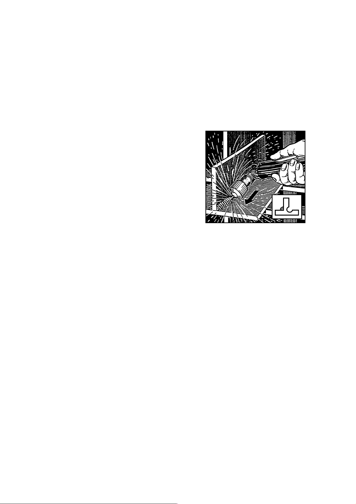
being spread on nozzle (see picture4). This operation
should be carried out with material thickness above
1/8" (3 mm). If you have to cut near angles or recesses
(see picture 5) it is recommended to use extended
electrodes and nozzles. Should circular cut be done it
is recommended to use caliper (supplied on request).
N.B. : Avoid keeping pilot arc uselessly on, in air to
avoid electrode, diffuser and nozzle consumption.
3.4 Cutting trouble
1) Insufficient penetration.
This may be due to:
high speed. Always make sure that arc thoroughly
−
passes through the piece to be cut and that it is not
tilted, when going forward, by an angle above 10 ÷ 15°
(see picture 6). It is thus avoided to wear nozzle (see
pict. 7) out and to burn the nozzle holder (see picture
8),
excessive thickness of piece (see graph of cutting
−
speed and thickness),
work clamp not properly in electric contact with piece,
−
worn nozzle and electrode,
−
too low cutting current.
−
N.B. : When the unit does not thoroughly pass through,
nozzle is clogged by scums.
2) Cutting arc switches off.
This may be due to:
worn nozzle, electrode or diffuser,
−
too high air pressure,
−
too low feed voltage.
−
3) Tilted cutting.
When cutting is tilted (see picture 9) switch the unit off,
loosen nozzle holder and turn nozzle by a quarter turn,
then lock and try again.
Repeat until cutting is straight (see picture 10).
4) Excessive wear of consumable parts.
This may be due to:
a) too low air pressure with respect to the
recommended one.
b) excessive burns on the end part of nozzle holder.
3.5 Practical recommendations
If the system air contains much humidity and oil it is
−
required to use a drying filter to avoid excessive
oxidation and wear of consumable parts, to avoid torch
damage or to reduce speed and quality of cutting.
Impurities of air favour oxidation of electrode and
−
nozzle and make it difficult to start pilot arc. If this
occurs, clean the end part of electrode and inside the
nozzle with fine abrasive paper.
Make sure that new electrode and nozzle to fit are
−
clean and degreased.
To avoid damages of torch always use genuine
−
spares.
3.6 Gouging
( Only for art. 494-496)
This operation permits to remove faulty welding, to
divide welded pieces, to prepare edges, etc. and is
almost exclusively used with manually controlled torch.
A nozzle Ø 3 mm should be used and spacer should be
fit into the nozzle holding bush. Spacer prevents molten
metal from burning the insulating material covering the
nozzle holding bush, while gouging. The power value to
be used is from 80 to 150A. This operation is carried
out by keeping torch tilted and advancing towards the
molten material thus moving it away by means of the
out flowing compressed air. Torch is tilted depending
on the penetration to be obtained. As molten slag tend
to stick on spacer and nozzle it is recommended to
clean them often to prevent effects (double arc)
destroying nozzle in few seconds. Because of intense
radiation emission (both infrared and ultraviolet) the
operator as well as persons nearby are recommended
to use proper protection.
3.7 Torch maintenance
Always disconnect the unit before any repair of
torch.
1) Replace wear parts
(picture 11)
.
The parts subject to wear are electrode 2, diffuser 3
and nozzle 4.
Either part may be only replaced after loosening nozzle
holder 5.
Electrode 2 should be replaced when a 1/16" (1,5 mm)
deep central crater develops (see picture 12).
ATTENTION!! Do not make sudden stresses when
unscrewing the electrode, but gradually force so as
to have the thread unlocked. Lubricate the thread of
the new electrode with silicone lubricant (on supply
with the unit). This new electrode has to be
screwed in its housing and locked without
tightening.
Nozzle 4 should be replaced when its central hole is
damaged or enlarged with respect to the new part (see
picture 13). Use of worn electrode quickly wears out the
nozzle. Excessive use of electrode causes overheating
and reduces the life of diffuser 3. Make sure that after
replacing it, nozzle 5 is tight enough.
ATTENTION!! Nozzle holder 5 should be only
screwed on head when electrode 2 diffuser 3 and
nozzle 4 are assembled.
2) Replace torch body 1
(see picture 11).
Remove the screw. Withdraw handle 9 from body 1 by
swaying it and making sure that button wires are not
torn when separating both parts. Withdraw the safety
contacts wires. Withdraw the contact . Unscrew fitting
after cutting the insulating hose . Assemble the new
body of torch making all above operations inversely.
11

Fitting is insulated by shrink hose stuck to the fitting
when heated by a small source (ex. a lighter).
Before replacing handle make sure that cables are far
away from each other and that fittings are tightly
secured.
3) Substitution of adapter 12
(see picture 11).
Remove the ring nut and cut the clamps locking cable
10. Loosen screw and extract cover. Extract the control
cable pins i and a and the red cable pins for pilot arc
and f. Cut the insulating sheath and loosen the adapter
body 12 from connector 11. Fit the new adapter body
carrying out all previous operations in reverse order.
Use sealing adhesive for threads in order to lock the
adapter body thread 12 on connector 11. Pins i and
of the control cable should be connected to contacts
and a of adapter body 12. Pins e and f of the red cable
for pilot arc should be connected to contacts e and f of
adapter body 12. Sheath acts as insulating material
and adheres to connector 11 after warming it up.
4) Replacement of cable 10
(see picture 11).
To replace the cable, follow instructions as per pos.2
and 3 and connect.
N.B.: Fitting should be properly insulated.
5) Replacement of handle with button.
To replace handle with button it is required to follow
instructions as for pos.2.
3.8 Maintenance and control
It is recommended to keep nozzle free from slag. Avoid
using sharpened bodies thus avoiding damaging the
nozzle hole. Even if the unit is provided with an
automatic device for water discharge, working
whenever air feed is closed, it is recommended to
check from time to time that no water remains in trap I
of reducer. It is required to clean from time to time the
unit inside and make it free from metal dust by means
of compressed air. Operations to be carried out inside
the unit must be effected after disconnecting feed
cable.
4 UTILISATION WITH TORCH P50
(on demand, only for art. 496.)
The machine is suitable to operate also with the P50
torch with the adapter (on demand). When you mount
this torch the machine is automatically arranged with a
cutting current of 50A max and with an adjustment
possibility which starts from 20A.
You will be able to cut, in contact with the piece, both
using our standard nozzle and electrode and our longer
nozzle and electrode.
Please note: It may be happen that when you use
the torch P50 the block device for exhausted
electrode could not operate.
5 GUIDE TO POSSIBLE FAILURES
Failures that could occur during machine operation are
listed below, this list being by no means exhaustive.
Repair, if any, should only be carried out by qualified
personnel.
Fuses protect primary and secondary windings of the
service transformer. In case of failure, first action to be
taken will be checking if any fuse is burnt.
1) Starting:
A)
If turning the switch A on (picture 1), the net pilot
lamp lightens but the machine does not start and
nothing happens when the torch push-button is
pressed, verify:
e
the efficiency of the service transformer and the
−
continuity of the electric circuits.
the efficiency of control circuits.
−
the presence of all the three phases in the machine's
−
plug.
a
i
that the flange 1 (picture 3) is correctly assembled.
−
B)
If turning the switch A (picture 1) on the net pilot
lamp lightens, the machine does not start but air flows
out of the torch when the push-button is pressed,
ensure:
that plant pressure is sufficient. The lamp signalling
−
insufficient pressure may be faulty.
that the microswitch of the air pressure switch (only
−
for art. 496), or the rectifier, or the power unit, or control
circuit are efficient.
that spare parts: electrode (2, pict. 11), diffuser (3,
−
pict. 11), nozzle (4, pict. 11), nozzle holder (5, pict. 11)
are correctly assembled.
2) Pilot arc:
The duration of the pilot arc in air is approx. 2/3 sec.,
even holding the torch push-button.
Air keeps flowing out as long as the push-button is held
and until approx. 1 minute after releasing it.
C)
If the machine is functioning and pressing the pushbutton no air flows out of the torch, verify:
that nozzle holder 5 (picture 11) is appropriately
−
fastened and fitted with electrode, diffuser and nozzle.
that thermostat is not temporarily off due to
−
transformer overload or discontinued (pilot lamp C,
picture 1). The lamp that indicates thermostat
intervention could be out of order.
that push-button, safety contacts, and control cables
−
on the torch are not discontinued.
that solenoid valve is efficient and that feeding is
−
correct; if not, replace control circuit, after checking the
continuity of the electrical connections.
D)
If the machine is working and pressing the pushbutton, the air flows out of the torch but the arc is not
activated, ensure:
that the torch has not short-circuited.
−
that pilot arc contactor is efficient .
−
that the contactor is feeded; if not, replace the control
−
circuit, after checking the electrical circuit.
that complete power unit - only for art. 496 - is
−
efficient.
that the high-tension circuit is efficient.
−
that impedance - only for art. 496 - has not short-
−
circuited. If pressing the torch push-button the hightension circuit generates sparkles on the platinum
points but the pilot arc is not activated, impedance
must be replaced.
3) Cutting
12

E)
If pilot arc turns on, but as it approaches to the
workpiece to be cut the machine stops and the pilot
lamp signalling "electrode exhausted" lights up even
with a new electrode, ensure:
that connection (pos.77 of the exploded view) is
−
firmly fastened and not discontinued in terms of
electricity (only art. 496).
that the solenoid valve is efficient and appropriately
−
supplied. For verifications see point H).
that the high-tension circuit and the control circuit are
−
efficient.
F)
If the torch arc turns on but then turns off again
when the torch is approached to the workpiece, verify:
that the workpiece is efficiently grounded.
−
that the control circuit is efficient.
−
G)
If the machine equipped with torch P50 does not set
full-scale setting at 50 A, verify (only for art. 496):
that contacts b and c of torch part adapter are short-
−
circuited.
that governing board or its connections are efficient.
−
H)
If the electrode and the nozzle wear too quickly or
cut quality is poor, ensure:
that the solenoid valve is efficient and appropriately
−
supplied.
Correct supply only occurs during cutting as the above
mentioned solenoid valve is only supplied under those
conditions.
If this is not the case, replace the control circuit after
verifying the continuity of the connections.
The efficiency of the solenoid valve is usually tested
observing the gauge pointer that has a slight movement
towards lower pressure values when the solenoid valve
is triggered, or also feeding it separately with outside
voltage.
13

BETRIEBSANLEITUNG FÜR PLASMASCHNEIDGERÄTE
Wichtig!
Lesen Sie bitte vor der Installation, Benützung oder Wartung
der Maschinen den Inhalt des Buches "Sicherheitsvorschriften
für die Benützung der Maschinen" und des
"Anleitungshandbuches" spezifisch für jeden Maschinen mit
Aufmerksamkeit. Falls Sie fragen haben, wenden Sie sich bitte
an Ihren Fachhändler.
1 SICHERHEITSVORRICHTUNGEN
Diese Geräteanlage ist mit folgenden Schutzvorrichtungen
versehen:
Thermische:
Zur Vermeidung eventueller Überlastungen,
hervorgehoben durch das Aufleuchten der Signalleuchte C
(siehe Abb. 1)
Pneumatische:
Um zu vermeiden, dass der Luftdruck
unzureichend ist, angebracht auf des Speisungsvorrichtung
der Brennerkopfes, hervorgehoben durch die Signalleuchte E
(siehe Abb. 1)
Elektrische:
1) Angebracht auf dem Brennerkörper, um zu
vermeiden, dass auf dem Brenner gefährliche Spannungen
sind, wenn die Düse, der Diffusor, die Elektrode oder der
Düsenträger ausgewechselt werden.
2) Um das Gerät abzuschalten, wenn die Elektrode soweit
abgenutzt ist, dass sie ausgewechselt werden muss. Dies wird
durch die Signalleuchte P (ausschließlich Art. 494) (Abb. 1)
angezeigt.
3) Angebracht auf der Platte der Maschine, um gefährliche
Spannungen auf dem Brenner zu vermeiden, wenn der
Brenner selbst ausgewechselt werden muss.
- Die Schutzvorrichtungen der Maschine nicht entfernen
oder unter Kurzschluß setzen.
- Nur Originalersatzteile verwenden.
- Eventuelle beschädigte Teile der Maschine oder des
Brenners immer durch Originalmaterial ersetzen.
- Keine Brennerkörper verwenden, die nicht die Originalen
sind.
- Die Maschine nicht ohne die Deckel laufen lassen. Das
wäre für den Maschinenwärter und die Personen, die sich
im Arbeitsbereit befinden, gefährlich und würde die
Maschine daran hindern, angemessen abzukühlen.
2 ERLÄUTERUNG DER TECHNISCHEN DATEN
IEC974-1 ....... Das Gerät ist gemäß diesen
EN60974-1 internationalen Vorschriften gebaut.
Art. ............... Seriennummer; bei Rückfragen ist diese
Nummer stets anzugeben.
. Dreiphasen -Transformator- Gleichrichter.
................ Abstiegskennlinie.
..... Für Plasmaschneiden geeignet.
................. Sekundär-Leerlaufspannung
U
0
X .................. Einschaltdauer. Die Einschaltdauer entspricht
dem Prozentsatz von 10 Minuten, in dem das
Gerät ohne Überhitzung bei einer bestimmten
Stromstärke arbeiten kann.
.................. Schneidstrom.
I
2
................. Sekundärspannung bei Schneidstrom I2.
U
2
................. Versorgungsnennspannung.
U
1
3~50/60Hz ..... Dreiphasenversorgung 50 oder 60Hz.
.................. Stromaufnahme bei entsprechendem
I
1
Schneidstrom I
.
2
IP 21 ............. Schutzart des Gehäuses.
Schutzart 1 als zweite Zahl bedeutet, dass
dieses Gerät zur Arbeit bei Regen im Freien
nicht geeignet ist.
.............. Zur Arbeit in Räumen mit erhöhter Gefahr
geeignet.
ANMERKUNG: Das Gerät ist ferner für die Arbeit in Räumen
mit Luftverunreinigungsgrad (siehe IEC 664)
ausgelegt.
3 BESCHREIBUNG DER VORRICHTUNGEN AUF DER
MASCHINE
(siehe Abb. 1 und Abb. 2)
A) Netzschalter.
B) Netzsignalleuchte.
C) Signalleuchte: Thermostat offen.
D) Manometer.
E) Signalleuchte: unzureichender Luftdruck.
G) Texas Kupplung.
H) Griff zur Regulierung des Schneidstroms.
I) Luftdruckminderer.
L) Speisekabel.
M) Kabelbefestiger.
P) Signalleuchte: verschlissene Elektrode.
R) Fester Anpasser des Brenners.
S) Speisesteckdose für Kühlaggregat.
T) Steckdose für Druckwächter.
U) Sicherung.
3.1 ZUSAMMENBAU
Die Maschine aus der Verpackung nehmen und den Griff mit
dem ausgerüsteten Inbus-Steckschlüssel montieren. Das
Gerät in einem angemessen belüfteten Raum aufstellen, der
möglichst nicht staubig ist, und darauf achten, den Ein- und
Austritt der Luft aus den Kuhlungsrippen nicht zu verstopfen.
Montieren Sie den Brenner (Abb. 3) auf der Maschine wie folgt:
1) Die M6x16 Schrauben von der Vorderplatte losschrauben.
Den Flansch 1 in den Schneidbrenner 2 einlegen, und den
Schneidbrenner an den Adapter 3 anschrauben. Den Flansch
einfügen, indem die Feuderbüchse in das entsprechende Loch
auf der Maschinenplatte gegeben wird. Den Flansch mit den
M6x16 Schrauben in den Löchern mit Gewindebüchsen
anziehen.
2) Zum Auswechseln des Schneidbrenners sind die M6x16
Schrauben loszuschrauben, der Flansch 1 ist zu entfernen.
14
 Loading...