

Elettro CF 3465, 3465D Use And Maintenance Manual

3465/230/50 3465D/230/50
3465/220/60 3465D/220/60
SPOTTER PER RADDRIZZATURA LAMIERA
SPOTTER FOR STRAIGHTENING SHEET METAL
SPOTTER DE REDRESSAGE DE TÔLE
SPOTTER ZUM AUSRICHTEN VON BLECHEN
SPOTTER PARA ENDEREZAMIENTO DE CHAPA
SPOTTER VOOR HET RECHTTREKKEN VAN PLAATWERK
PINTAOIKAISULAITE
Manuale d’uso e manutenzione
Use and maintenance manual
Manuel d’utilisation et de maintenance
Bedienungs-und Wartungsanleitung
Manual de uso y mantenimiento
Gebruik- en onderhoudshandleiding
Käyttö- ja huolto-opas
IT EN FR DE ES NL FI
DMC6100001
MANUALE D’USO SPOTTER 3465 R1
17/12 /2018


3465
1
9
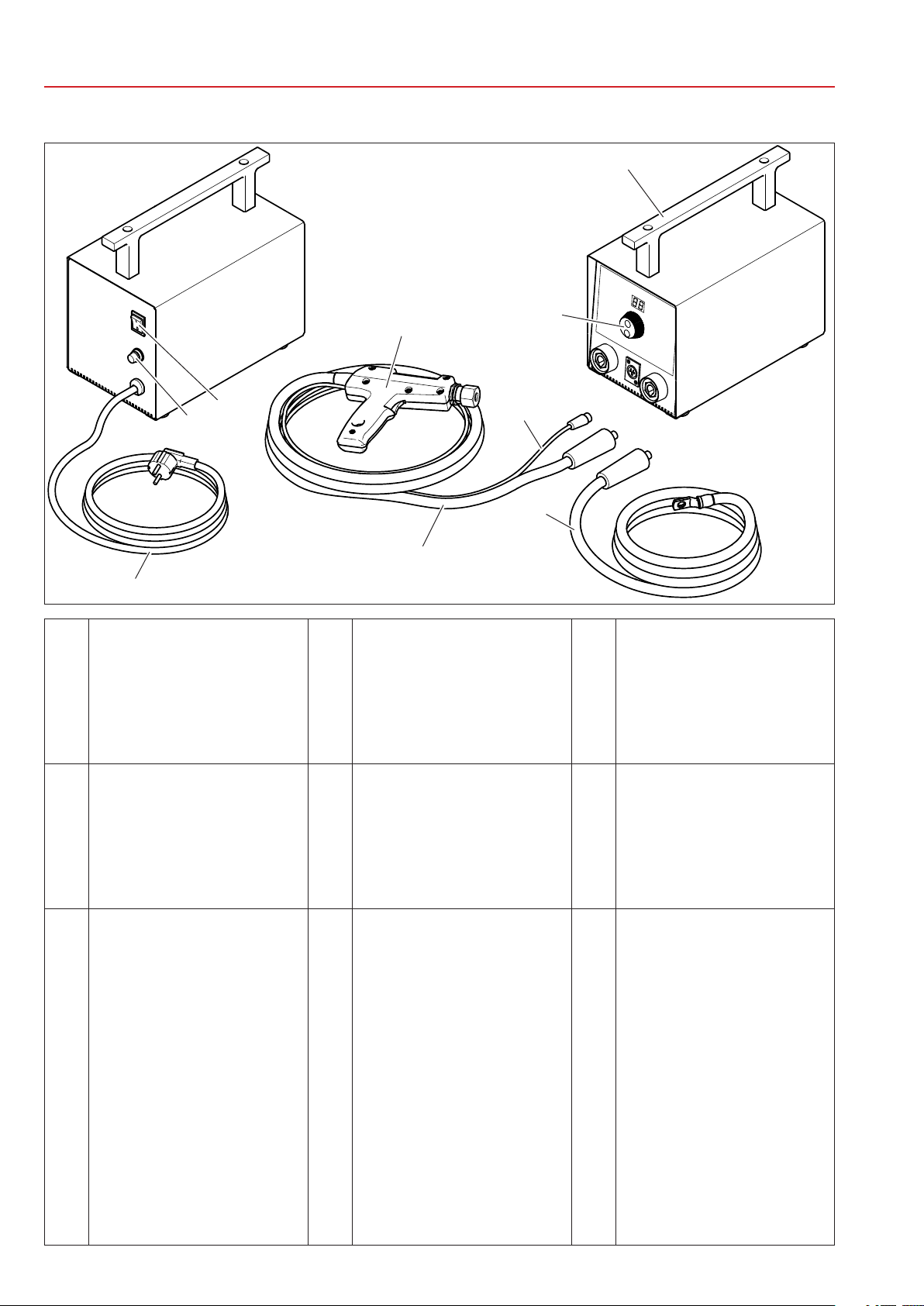
Maniglia per trasporto
Carrying handle
Poignée de transport
1
Transportgriff
Manija para transporte
Transporthandvat
Kuljetuskahva
Manopola di regolazione
Adjustment knob
Commande de réglage
2
Regler
Perilla de regulación
Regelknop
Säätönuppi
8
2
7
6
3
4
5
Cavo di saldatura per massa
Welding earth cable
Câble de soudure pour masse
4
Massekabel
Cable de soldadura para masa
Massalaskabel
Hitsauskaapeli, maa
Cavo di saldatura per pistola
Welding gun cable
Câble de soudure pour pistolet
5
Schweißkabel für Pistole
Cable de soldadura para pistola
Laskabel voor pistool
Hitsauskaapeli, pistooli
Interruttore generale
Main switch
Interrupteur général
Hauptschalter
7
Interruptor general
Hoofdschakelaar
Pääkatkaisin
Pistola multifunzione
Multifunction gun
Pistolet multifonction
8
Multifunktionspistole
Pistola multifunción
Multifunctioneel pistool
Monitoimipistooli
Cavo di comando start
Start command cable
Câble de commande start
3
Start-Steuerkabel
Cable de comando de inicio
Start-bedieningskabel
Käynnistyksen ohjauskaapeli
Fusibile di protezione
elettrica
Electrical protection fuse
Fusible de protection
électrique
6
Elektrosicherung
Fusible de protección
eléctrica
Veiligheidszekering
Suojasulake
Cavo di alimentazione
• 3465/230/50 - Schuko
• 3465/220/60 - A cablare
Power cable
• 3465/230/50 - Schuko
• 3465/220/60 - Attachable fittings
Câble d’alimentation
• 3465/230/50 - Schuko
• 3465/220/60 - À câbler
Netzanschlusskabel
9
• 3465/230/50 - Schuko
• 3465/220/60 - Zu verkabeln
Cable de alimentación
• 3465/230/50 - Schuko
• 3465/220/60 - Cablear
Voedingskabel
• 3465/230/50 - Schuko
• 3465/220/60 - Voor bekabeling
Virtakaapeli
• 3465/230/50 - Suko
• 3465/220/60 - Johdotettava
I
3465D
1
9
Maniglia per trasporto
Carrying handle
Poignée de transport
1
Transportgriff
Manija para transporte
Transporthandvat
Kuljetuskahva
8
7
2
3
6
4
5
Cavo di saldatura per massa
Welding earth cable
Câble de soudure pour masse
4
Massekabel
Cable de soldadura para masa
Massalaskabel
Hitsauskaapeli, maa
Interruttore generale
Main switch
Interrupteur général
Hauptschalter
7
Interruptor general
Hoofdschakelaar
Pääkatkaisin
Manopola di regolazione
Adjustment knob
Commande de réglage
2
Regler
Perilla de regulación
Regelknop
Säätönuppi
Cavo di comando start
Start command cable
Câble de commande start
3
Start-Steuerkabel
Cable de comando de inicio
Start-bedieningskabel
Käynnistyksen ohjauskaapeli
Cavo di saldatura per pistola
Welding gun cable
Câble de soudure pour pistolet
5
Schweißkabel für Pistole
Cable de soldadura para pistola
Laskabel voor pistool
Hitsauskaapeli, pistooli
Fusibile di protezione
elettrica
Electrical protection fuse
Fusible de protection
électrique
6
Elektrosicherung
Fusible de protección
eléctrica
Veiligheidszekering
Suojasulake
Pistola multifunzione
Multifunction gun
Pistolet multifonction
8
Multifunktionspistole
Pistola multifunción
Multifunctioneel pistool
Monitoimipistooli
Cavo di alimentazione
• 3465/230/50 - Schuko
• 3465/220/60 - A cablare
Power cable
• 3465/230/50 - Schuko
• 3465/220/60 - Attachable fittings
Câble d’alimentation
• 3465/230/50 - Schuko
• 3465/220/60 - À câbler
Netzanschlusskabel
9
• 3465/230/50 - Schuko
• 3465/220/60 - Zu verkabeln
Cable de alimentación
• 3465/230/50 - Schuko
• 3465/220/60 - Cablear
Voedingskabel
• 3465/230/50 - Schuko
• 3465/220/60 - Voor bekabeling
Virtakaapeli
• 3465/230/50 - Suko
• 3465/220/60 - Johdotettava
II
3465 / 3465D
9
8
1
2
3
3
7
6
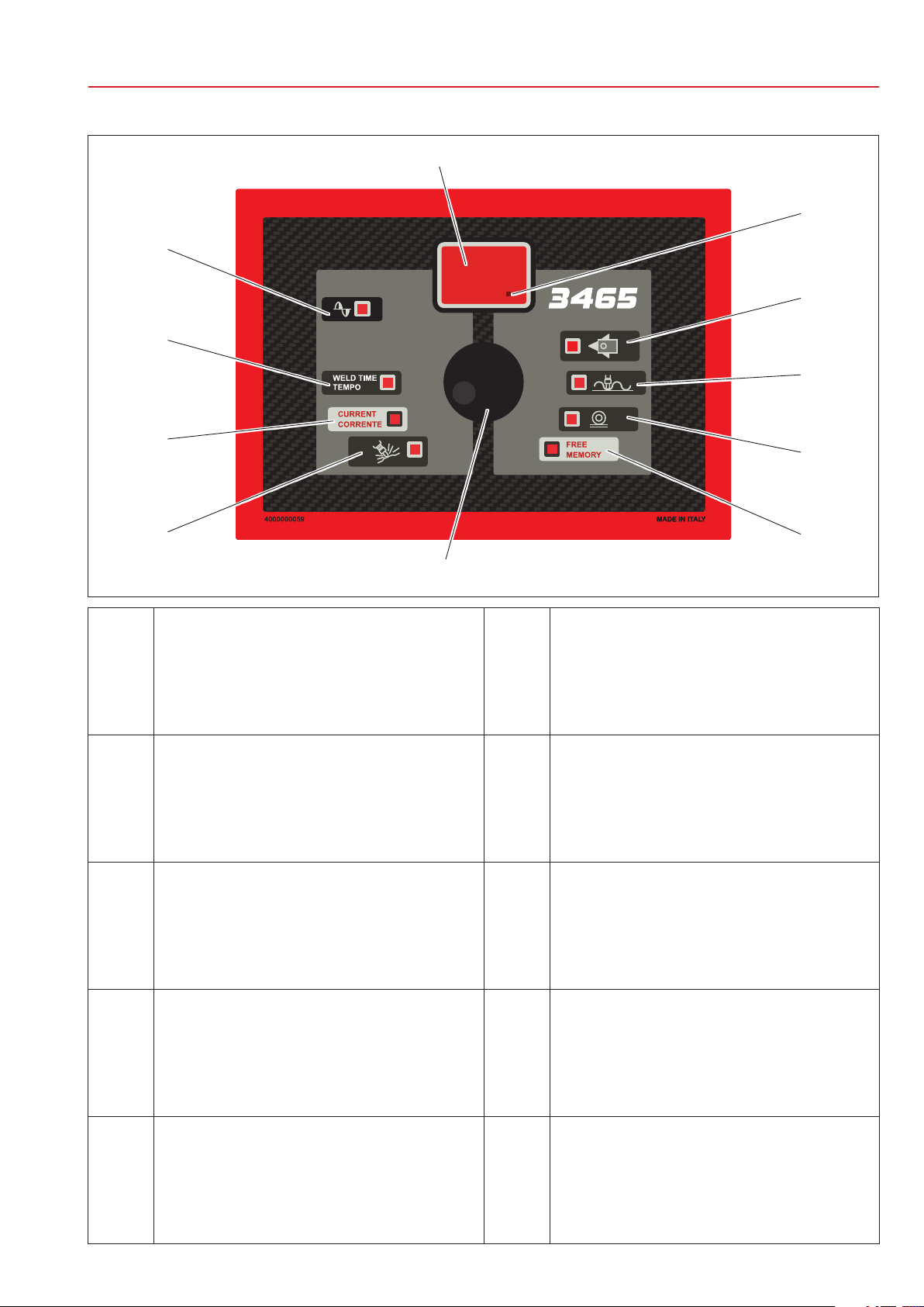
Display
Display
Écran
1
Display
Pantalla
Display
Näyttö
Indicatore ciclo automatico attivo
Automatic cycle active indicator
Indicateur cycle automatique actif
2
Anzeige automatischer Zyklus aktiv
Indicador de ciclo automático activo
Indicator automatische cyclus actief
Automaattiajon merkkivalo
Programmi predefiniti
Preset programs
Programmes prédéfinis
3
Vorgeingestellte Programme
Programas predeterminados
Voorgedefinieerde programma's
Määritetyt ohjelmat
Memoria libera
Free memory
Mémoire libre
4
Freier Speicher
Memoria libre
Vrij geheugen
Vapaata muistitilaa
Manopola di regolazione
Adjustment knob
Commande de réglage
5
Regler
Perilla de regulación
Regelknop
Säätönuppi
3
4
5
Programma per riscaldamento localizzato
Localised heating program
Programme de chauffage localisé
6
Programm für lokale Erwärmung
Programa para calentamiento localizado
Programma voor lokale verwarming
Paikallisen kuumennuksen ohjelma
Regolazione potenza di saldatura
Welding power adjustment
Réglage puissance de soudure
7
Einstellung Schweißleistung
Regulación de potencia de soldadura
Regeling lasvermogen
Hitsaustehon säätö
Regolazione tempo di saldatura
Adjustment of welding time
Réglage du temps de soudure
8
Einstellung Schweißzeit
Regulación de tiempo de soldadura
Regeling lastijd
Hitsausajan säätö
Indicatore di saldatura in corso
Welding in progress indicator
Indicateur de soudure en cours
9
Anzeige laufende Schweißung
Indicador de soldadura en curso
Indicator bezig met lassen
Hitsauksen merkkivalo
III

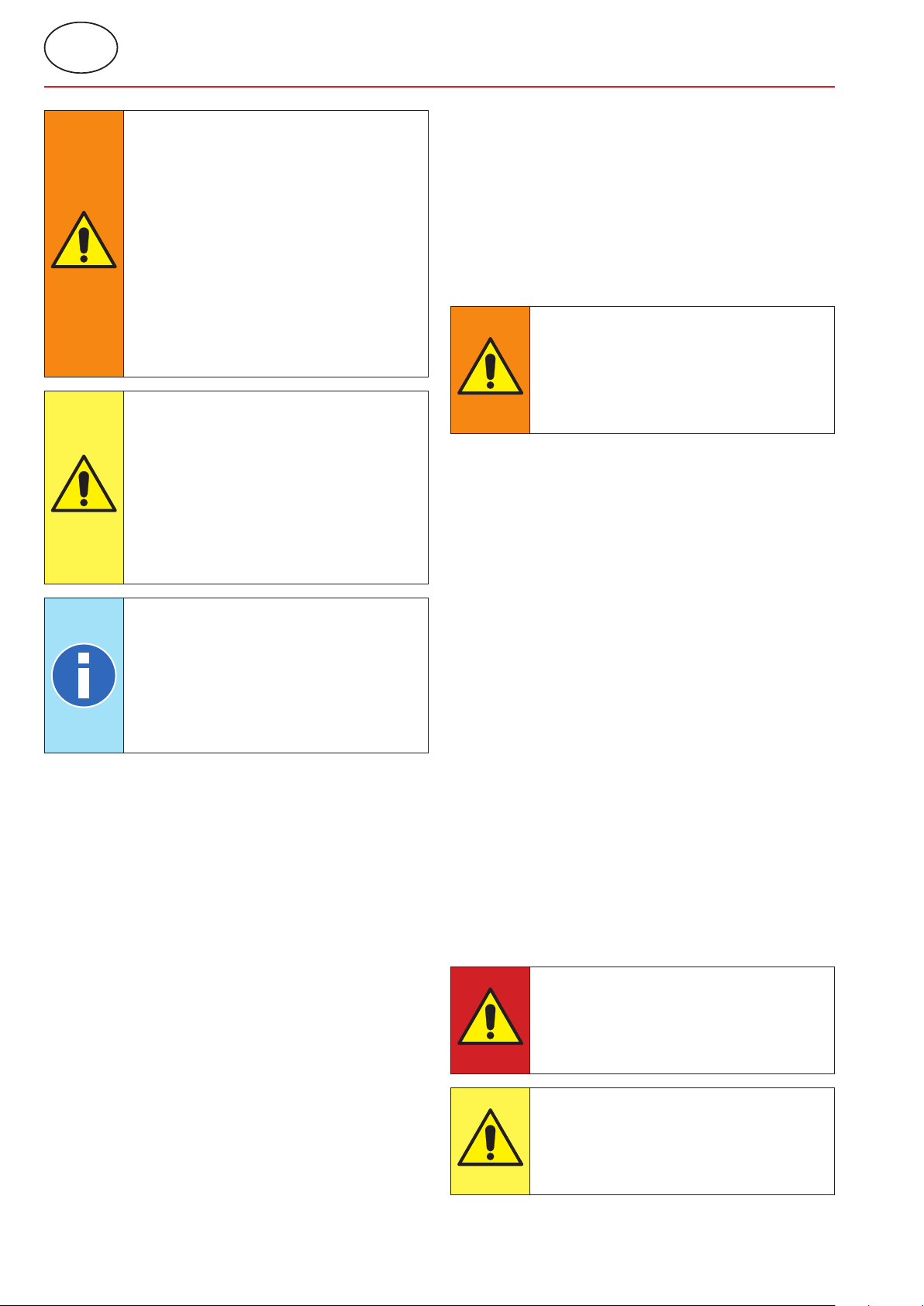
AVVISO / NOTE / NOTE / HINWEIS / AVISO / OPMERKING / TIEDOTUS
Istruzione che si riferisce alla descrizione di una condotta necessaria per affrontare il normale
utilizzo della macchina.
An instruction referring to a description of necessary behaviour for normal use of the machine.
Instruction relative à la description du comportement à observer pour la bonne utilisation de la
machine.
Anleitung, die sich auf die Beschreibung einer notwendigen Verhaltensweise bezieht, notwendig für die
normale Verwendung der Maschine.
Instrucción que se refiere a la descripción de una acción necesaria para el uso normal de la
máquina.
Instructie die verwijst naar een beschrijving van gedrag dat noodzakelijk is voor de normale werking van
de machine.
Koneen normaalikäytössä tarvittavaan toimintaan viittava ohje.
ATTENZIONE / CAUTION / ATTENTION / ACHTUNG / ATENCIÓN / LET OP / HUOMIO
Istruzione che si riferisce a una situazione di rischio potenziale che, se non evitata, può causare
danni di minore entità relativi alla sicurezza della macchina.
An instruction referring to a situation of potential risk, which, if not avoided, could cause minor damage
with regard to the safety of the machine.
Instruction relative à une situation de risque potentiel qui, si elle n’est pas évitée, peut causer des
dommages mineurs relatifs à la sécurité de la machine.
Anleitung, die sich auf eine potentielle Risiko-Situation bezieht, die bei Nichtvermeidung, geringfügige
Schäden in Bezug auf die Sicherheit der Maschine verursachen kann.
Instrucción que se refiere a una situación de riesgo potencial que, si no se evita, puede causar
daños de menor entidad relativos a la seguridad de la máquina.
Instructie die verwijst naar een potentieel gevaarlijke situatie die, als die niet wordt vermeden, kan leiden
tot lichte schade met betrekking tot de veiligheid van de machine.
Mahdollinen vaaratilanne, jonka seurauksena saattaa olla lieviä, koneen turvallisuuteen liittyviä
vaurioita.
AVVERTENZA / WARNING / AVERTISSEMENT / WARNHINWEIS / ADVERTENCIA /
WAARSCHUWING / VAROITUS
Istruzione che si riferisce a una situazione di rischio potenziale che, se non evitata, può causare
morte o danno grave alla salute.
An instruction referring to a situation of potential risk, which, if not avoided, could cause death or serious
damage to health.
Instruction relative à une situation de risque potentiel qui, si elle n’est pas évitée, peut entraîner la
mort ou causer de graves blessures/lésions.
Anleitung, die sich auf eine potentielle Risiko-Situation bezieht, die bei Nichtvermeidung, den Tod oder
schwerwiegende gesundheitliche Schäden hervorrufen kann.
Instrucción que se refiere a una situación de riesgo potencial que, si no se evita, puede causar la
muerte o daños graves a la salud.
Instructie die verwijst naar een potentieel gevaarlijke situatie die, als die niet wordt vermeden, kan leiden
tot ernstig persoonlijke letsel of overlijden.
Mahdollinen vaaratilanne, jonka seurauksena saattaa olla vakava terveyshaitta tai kuolema.
PERICOLO / HAZARD / DANGER / GEFAHR / PELIGRO / GEVAAR / VAARA
Istruzione che si riferisce a una situazione di rischio imminente che, se non evitata, causa morte
istantanea o danno grave e permanente alla salute.
An instruction referring to a situation of imminent risk, which, if not avoided, causes immediate death or
serious and permanent damage to health.
Instruction relative à une situation de risque imminent qui, si elle n’est pas évitée, peut entraîner la
mort instantanée ou causer de graves blessures/lésions permanentes.
Anleitung, die sich auf eine potentielle Risiko-Situation bezieht, die bei Nichtvermeidung, den sofortigen
Tod oder schwerwiegende unddauerhafte gesundheitliche Schäden hervorrufen kann.
Instrucción que se refiere a una situación de riesgo inminente que, si no se evita, causa la muerte
instantánea o daño grave y permanente a la salud.
Instructie die verwijst naar een situatie met dreigend gevaar die, als die niet wordt vermeden, direct
dodelijk kan zijn of kan leiden tot ernstig persoonlijk en permanent letsel.
Välitön vaaratilanne, jonka seurauksena saattaa olla vakava ja pysyvä terveyshaitta tai välitön
kuolema.
IV
Sommario / Index / Table des matières / Inhaltsangabe / Índice / Inhoud / Sisältö
1 INFORMAZIONI GENERALI .................................................................................IT1
2 INFORMAZIONI DI SICUREZZA ..........................................................................IT1
3 CARATTERISTICHE .............................................................................................. IT3
4 INSTALLAZIONE .................................................................................................. IT3
IT
5 USO ....................................................................................................................... IT4
6 ALLARMI ...............................................................................................................IT7
7 MANUTENZIONE ..................................................................................................IT7
8 SMALTIMENTO .................................................................................................... IT8
9 ALLEGATI ............................................................................................................. IT8
EN
1 GENERAL INFORMATION ................ EN1
2 SAFETY INFORMATION ................... EN1
3 FEATURES ......................................... EN3
4 INSTALLATION ................................. EN3
5 USE .................................................... EN4
6 ALARMS ............................................ EN7
7 MAINTENANCE ................................. EN7
8 DISPOSAL .........................................EN8
9 ANNEXES ..........................................EN8
DE
1 ALLGEMEINE INFORMATIONEN ..... DE1
2 SICHERHEITSINFORMATION .......... DE1
3 EIGENSCHAFTEN ............................. DE3
4 INSTALLATION ................................. DE3
5 VERWENDUNG ................................. DE4
6 ALARME ............................................ DE7
7 WARTUNG ......................................... DE7
8 ENTSORGUNG .................................. DE8
9 ANLAGEN .......................................... DE8
FR
1 INFORMATIONS GÉNÉRALES...........FR1
2 INFORMATIONS DE SÉCURITÉ ......... FR1
3 CARACTÉRISTIQUES .........................FR3
4 INSTALLATION ..................................FR3
5 UTILISATION ...................................... FR4
6 ALARMES ...........................................FR7
7 ENTRETIEN ........................................FR7
8 ÉLIMINATION ....................................FR8
9 ANNEXES ...........................................FR8
ES
1 INFORMACIÓN GENERAL ................. ES1
2 INFORMACIÓN DE SEGURIDAD ....... ES1
3 CARACTERÍSTICAS ...........................ES3
4 INSTALACIÓN .................................... ES3
5 USO ..................................................... ES4
6 ALARMAS ...........................................ES7
7 MANTENIMIENTO ............................. ES7
8 ELIMINACIÓN ....................................ES8
9 ANEXOS .............................................ES8
NL
1 ALGEMENE INFORMATIE .................NL1
2 VEILIGHEIDSINFORMATIE ...............NL1
3 KENMERKEN ......................................NL3
4 INSTALLATIE ...................................... NL3
5 GEBRUIK ........................................... NL4
6 ALARMEN ..........................................NL7
7 ONDERHOUD ....................................NL7
8 AFVOER ............................................. NL8
9 BIJLAGEN .......................................... NL8
FI
1 YLEISIÄ TIETOJA ................................ FI1
2 TURVALLISUUSTIETOJA .................... FI1
3 OMINAISUUDET ................................. FI3
4 ASENNUS ............................................ FI3
5 KÄYT TÖ ...............................................FI4
6 HÄLYT YK SET ...................................... FI7
7 HUOLTO .............................................. FI7
8 LOPPUKÄSITTELY .............................. FI8
9 LIITTEET ..............................................FI8
V


Testo originale
IT
1 INFORMAZIONI GENERALI
1.1 Scopo del manuale
Questo manuale è stato realizzato per fornire le
informazioni necessarie per una corretta installazione,
utilizzo e manutenzione dello spotter.
All’interno del presente manuale lo spotter può essere
definito più genericamente come macchina.
Il costruttore si riserva di apportare eventuali modifiche
tecniche sul presente manuale e sulla macchina senza
obbligo di preavviso.
1.2 Garanzia
1.2.1 Copertura della garanzia
Il costruttore garantisce i suoi prodotti da tutti i difetti
di lavorazione e si impegna a sostituire gratuitamente
ai propri Clienti eventuali pezzi, riscontrati difettosi
dalla casa costruttrice stessa.
1.2.2 Durata della garanzia
Il costruttore garantisce i suoi prodotti per 24 mesi dalla
data di vendita riportata sul documento di acquisto.
1.2.3 Esclusioni dalla garanzia
Sono esclusi da garanzia i componenti di normale
usura quali: Fusibili.
1.3 Richiesta di assistenza tecnica
Il servizio di assistenza / post-vendita è a disposizione
per chiarimenti o per l’invio di pezzi di ricambio.
Specificare sempre:
• Nome Cliente e dati identificativi.
• Dati identificativi dell’apparecchiatura.
• Documento d’acquisto
In caso di bisogno rivolgersi a:
1.4 Targa per l’identificazione della
macchina
(Riferimenti relativi all'immagine allegata A1)
I dati di identificazione del costruttore e della macchina
sono stampati su una targa identificativa.
Sulla targa sono riportati i seguenti dati:
1. Seriale dell’apparecchiatura.
2. Codice dell’apparecchiatura.
3. Anno di costruzione.
4. Dati tecnici macchina.
5. Dati tecnici pistola.
AVVERTENZA
E’ vietato manomettere, incidere, alterare
o asportare la targa di identificazione
della macchina.
AVVISO
Nel caso in cui per motivi accidentali
la targa di identificazione risultasse
danneggiata notificare immediatamente
l’accaduto all'assistenza tecnica.
2 INFORMAZIONI DI SICUREZZA
2.1 Norme generali
Per mantenere il livello massimo di sicurezza del
dispositivo è necessario che:
• gli operatori e i manutentori abbiano letto e
compreso le istruzioni relative all’installazione e
all’uso della macchina;
• vengano eseguiti tut ti gli inter venti di manutenzione
periodica descritti al capitolo Manutenzione;
• vengano rispettate le seguenti indicazioni di
sicurezza:
PERICOLO
Non utilizzare la macchina se si è
AVVISO
È obbligatorio per il Cliente acquistare
sempre accessori e ricambi originali,
oppure equivalenti autorizzati per iscritto
dal costruttore.
portatori di protesi biomedicali, per
maggiori informazioni consultare il
paragrafo “Pericoli derivanti da campi
magnetici”.
Non toccare le parti soggette a
surriscaldamento, per maggiori
informazioni consultare il paragrafo
“Pericoli di ustione e incendio”.
Non utilizzare la macchina in
prossimità di sostanze esplosive e/o
materiali infiammabili.
Non utilizzare la macchina con i cavi
elettrici danneggiati.
Non utilizzare la macchina su superfici
bagnate.
IT-1
IT
Testo originale
AVVERTENZA
Verificare che il dispositivo sia connesso
ad una presa di alimentazione dotata
di messa a terra.
Inserire la spina nella presa fino a
fine corsa, non utilizzare allo stesso
tempo la presa per altri dispositivi
e non rimuoverla tirando il cavo di
alimentazione.
Spegnere l’interruttore generale e
scollegare il cavo di alimentazione ogni
qual volta la saldatrice venga lasciata
incustodita e/o prima di effettuare
qualsiasi intervento di manutenzione.
ATTENZIONE
Mantenere il cavo elettrico lontano
da sorgenti di calore, bordi affilati o
taglienti.
Non trasportare la macchina tenendola
dal cavo di alimentazione.
Non accendere o spegnere
l’alimentazione, se non strettamente
necessario, questo potrebbe causare
l’interruzione del fusibile.
AVVISO
Se si notano anomalie durante
l’uso, staccare la spina e contattare
l’assistenza tecnica.
Eseguire i controlli periodici e gli
interventi di manutenzione ordinaria.
Utilizzare solamente componenti e
ricambi originali del costruttore.
2.2 Elenco dei Dispositivi di sicurezza e
protezione presenti sul dispositivo
La macchina è provvista di dispositivi di sicurezza atti
alla protezione dei lavoratori e della macchina stessa.
È vietato manomettere, modificare o tentare di eludere
in alcun modo i sistemi di sicurezza della macchina.
2.2.1 Protezione da surriscaldamento
La macchina è dotata di un sensore per monitorare
la temperatura e avvisare l'operatore in caso di
surriscaldamento eccessivo.
Nel caso in cui si superi la soglia massima si attiva un
allarme ed è necessario spegnere la macchina fino al
completo raffreddamento.
2.2.2 Protezione da sovratensione
La macchina è dotata di un fusibile per proteggere la
macchina da sbalzi di tensione.
Nel caso in cui il fusibile si sia interrotto è necessario
procedere con la sostituzione dello stesso.
2.3 Pittogrammi
2.3.1 Segnali di sicurezza ed informazione
Sulla macchina possono essere presenti dei segnali che
avvertono dei rischi relativi alla zona limitrofa, delle
targhe riportanti informazioni e/o pittogrammi per un
utilizzo corretto e sicuro della macchina.
2.4 Obbligo di utilizzo di DPI (Dispositivi
Protezione Individuale)
AVVERTENZA
Il personale deve indossare adeguati
dispositivi di protezione individuale
(occhiali, guanti, grembiuli o altro vestiario)
per proteggere l’operatore da eventuali
schizzi di materiale incandescente.
2.5 Rischi residui
Il costruttore si esime da qualsiasi responsabilità per
danni a persone, cose o alla macchina stessa causati
da un impiego non corretto, dalla mancanza e/o
superficiale osservanza dei criteri di sicurezza riportati
nel presente manuale, dalle manomissioni anche lievi
e dall’impiego di parti di ricambio non originali o non
compatibili.
Le informazioni fornite nel presente manuale si
riferiscono all’utilizzo del prodotto secondo quanto
previsto dal costruttore; nel caso di un uso non
conforme a quanto riportato nel presente manuale è
responsabilità dell’utente eseguire un’analisi del rischio.
2.5.1 Pericolo di natura ergonomica
Durante le attività di utilizzo della macchina, l’operatore
può essere esposto a rischi di natura ergonomica,
quali sovraccarico o posizioni incongrue.
Si raccomanda di eseguire una valutazione di rischio
ergonomico in relazione agli effettivi compiti lavorativi
eseguiti dall’utilizzatore della macchina.
2.5.2 Pericoli derivanti da campi magnetici
Durante le attività di utilizzo della macchina, l’operatore
è esposto ad un campo elettromagnetico dovuto al
passaggio di correnti continue elevate.
PERICOLO
È vietato utilizzare la macchina se si è
portatori di protesi biomedicali (es. pacemaker, protesi metalliche ecc.) senza aver
consultato il proprio medico curante.
ATTENZIONE
I campi magnetici generati dalla macchina
possono causare forte attrazione su
metalli magnetici o danneggiare le
apparecchiature magnetosensibili.
IT-2

Testo originale
IT
Per limitare l’esposizione al campo elettromagnetico:
• tenere i cavi di saldatura il più possibile vicini tra loro
(eventualmente arrotolandoli) e lontani dal corpo
dell'utilizzatore (non posizionare il corpo all’interno
del percorso descritto dai cavi);
• tenere i cavi di saldatura dal lato della mano che
impugna la pistola multifunzione;
• saldare la massa a puntare il più possibile vicino
all’area su cui devono essere effettuate le lavorazioni
successive.
2.5.3 Pericolo di inalazione fumi
Analizzare le condizioni di lavoro ed utilizzare adeguati
impianti di aspirazione nel caso in cui le operazioni di
saldatura generino fumi.
2.5.4 Pericolo di ustione
I cavi e gli elettrodi della macchina possono raggiungere
temperature elevate in caso di utilizzo prolungato.
PERICOLO
Rimuovere gli elettrodi utilizzando una
pinza e prestare attenzione ad evitare
ogni contatto con le parti ustionanti.
L’elevata corrente elettrica utilizzata dalla macchina
può surriscaldare gli oggetti di metallo posizionati
nelle sua vicinanze.
3 CARATTERISTICHE
3.1 Descrizione macchina
Lo spotter 3465 è una macchina concepita per la
raddrizzatura mediante saldatura o riscaldamento
localizzato. La macchina può essere impostata
manualmente e i programmi possono essere salvati per
le lavorazioni più comuni. Il trasformatore e la pistola
sono dotati di protezione termica.
3.2 Uso previsto
La macchina deve essere utilizzata in ambienti
industriali, ambienti chiusi, areati, asciutti, liberi da
polvere, vapori ed esalazioni acide. Il luogo deve
essere adeguatamente illuminato. È vietato qualsiasi
intervento di modifica in quanto invalidano la
certificazione CE nonchè la garanzia.
3.3 Uso improprio
La saldatrice non deve essere utilizzata per altri scopi,
se non quelli descritti nel sottocapitolo "Uso previsto".
In particolare non deve essere usata in ambiente
domestico o su linee di alimentazione pubbliche a
bassa tensione.
4 INSTALLAZIONE
AVVERTENZA
Durante l'utilizzo della macchina non
indossare anelli, orologi metallici, e vestiti
con parti od accessori metallici.
2.5.5 Pericolo di incendio
Le superfici su cui si eseguono le lavorazioni possono
raggiungere temperature elevate.
AVVERTENZA
Verificare che non vi siano materiali
infiammabili a contatto o in prossimità
delle superfici sulle quali si deve lavorare.
Gli elettrodi della macchina possono raggiungere
temperature elevate, in caso di utilizzo prolungato.
AVVERTENZA
Riporre gli elettrodi in un luogo adatto
a consentirne il raffeddamento in totale
sicurezza (esempio: per terra).
Tenere la zona circostante libera da
materiali infiammabili.
Al ricevimento della macchina verificare l'integrità
dell’imballo e segnalare all'assistenza tecnica eventuali
anomalie riscontrate.
4.1 Trasporto e movimentazione della
macchina imballata
I mezzi di sollevamento e trasporto per l’imballo
devono avere una portata adeguata.
4.2 Stoccaggio
Verificare che le caratteristiche dell’ambiente in cui si
deve stoccare l'imballo corrispondano a:
• Temperatura: +5 /+40 °C;
• Umidità relativa 60% Max.
Valori non compresi tra quelli sopra indicati possono
compromettere il funzionamento della macchina.
4.3 Installazione
L’installazione deve essere eseguita da personale a
conoscenza delle norme di sicurezza e seguendo le
indicazioni contenute in questo manuale.
La macchina è progettata per essere utilizzata in
ambienti industriali ed è classificata come saldatrice a
resistenza di classe A.
IT-3
ATTENZIONE
Le saldatrici di classe A non sono
previste per l’impiego su linee pubbliche
a bassa tensione che alimentano
ambienti domestici. Questo può causare
interferenze di radiofrequenza.
IT
Testo originale
Prima di collegare la macchina verificare che la tensione
di rete coincida con quella indicata sulla targa.
ATTENZIONE
La macchina può essere utilizzata
solamente alla tensione di alimentazione
indicata sulla targa e non è predisposta
per poter essere regolata per altre tensioni
di alimentazione.
Verificare che il conduttore di protezione dell’impianto
elettrico sia efficiente e corrispondente alla normativa
vigente.
L’installazione può essere eseguita solamente su una
linea con sistema di messa a terra di tipo TN o TT.
La massima tensione di alimentazione ammessa tra L e
N è di 230Vac.
La massima differenza di potenziale di L ed N rispetto a
terra deve essere di 230Vac.
La tensione di alimentazione è riportata nell'allegato
“Dati tecnici”.
Si consiglia di non utilizzare prolunghe se non
strettamente necessarie.
5 USO
5.1 Accensione macchina
Accendere il dispositivo premendo l’interruttore
generale in posizione ‘I’ - ON.
5.2 Avvio del sistema di controllo
All'accensione della macchina tutti i led si accendono
per un paio di secondi.
Sul display viene visualizzata:
• La frequenza di rete riconosciuta dal sistema per un
tempo di 2 secondi.
• La versione del software di controllo per 2 secondi.
• La modalità di funzionamento attiva (A0 o A1) per 2
secondi.
Al termine della fase di accensione, se non vengono
rilevati errori o anomalie, si spengono tutti i led tranne
il led WELD TIME/TEMPO e sul display viene visualizzato
il valore del tempo attualmente impostato.
5.3 Selezione programmi e
impostazione parametri di saldatura
5.3.1 Impostazione modalità di avvio saldatura
• Ruotare la manopola fino ad attivare la funzione
WELD TIME/TEMPO (led acceso).
• Premere la manopola per entrare nella modalità
modifica.
• Ruotare la manopola fino a raggiungere il valore
minimo.
• Premere e ruotare nuovamente la manopola per
selezionare la modalità di avvio saldatura:
• A0 - Modalità AUTOSTART OFF (il ciclo si avvia
premendo il grilletto della pistola).
• A1 - Modalità AUTOSTART ON (il ciclo si avvia
automaticamente quando la punta entra a
contatto con la superficie).
• Premere nuovamente la manopola per confermare.
5.3.2 Impostazione tempo di saldatura
• Ruotare la manopola fino ad attivare la funzione
WELD TIME/TEMPO (led acceso).
• Premere la manopola per entrare nella modalità
modifica.
• Ruotare la manopola per variare il tempo di saldatura
fino ad ottenere il valore desiderato.
• Premere nuovamente la manopola per confermare.
5.3.3 Impostazione corrente di saldatura
• Ruotare la manopola fino ad attivare la funzione
CURRENT/CORRENTE (led acceso).
• Premere la manopola per entrare nella modalità
modifica.
• Ruotare la manopola per variare la corrente elettrica
fino ad ottenere il valore desiderato.
• Premere nuovamente la manopola per confermare.
5.3.4 Selezione programma per riscaldamento
localizzato e impostazione
• Ruotare la manopola fino ad attivare il programma
per riscaldamento localizzato (led acceso).
• Premere la manopola per entrare nella modalità
modifica.
• Ruotare la manopola per variare la corrente elettrica
fino ad ottenere il valore desiderato.
• Premere nuovamente la manopola per confermare.
AVVISO
Nel programma per riscaldamento
localizzato non è necessario definire il
tempo di saldatura.
Il ciclo resterà attivo fintanto che il grilletto
della pistola sarà premuto.
5.3.5 Selezione programma predefinito
• Ruotare la manopola sul programma predefinito
che si intende utilizzare (led acceso).
• Sul display vengono visualizzati il tempo e la
potenza salvati nel programma.
• Premere nuovamente la manopola per confermare.
AVVISO
Ruotando la manopola è possibile variare
le impostazioni salvate del ± 10%.
IT-4

Testo originale
IT
5.3.6 Salvataggio programma predefinito
• Ruotare la manopola fino ad attivare la funzione
WELD TIME/TEMPO (led acceso).
• Premere la manopola per entrare nella modalità
modifica.
• Ruotare la manopola per variare il tempo di saldatura
fino ad ottenere il valore desiderato.
• Premere nuovamente la manopola per confermare.
• Ruotare la manopola fino ad attivare la funzione
CURRENT/CORRENTE (led acceso).
• Premere la manopola per entrare nella modalità
modifica.
• Ruotare la manopola per variare la corrente elettrica
fino ad ottenere il valore desiderato.
• Premere nuovamente la manopola per confermare.
• Ruotare la manopola fino ad attivare il programma
predefinito che si intende modificare (led acceso).
• Premere la manopola per 5 secondi.
• Sul display vengono visualizzati il tempo e la
potenza aggiornati nel programma.
• Premere nuovamente la manopola per 5 secondi
per salvare.
5.4 Impiego del saldatore
PERICOLO
È vietato utilizzare la macchina se si è
portatori di protesi biomedicali (es. pacemaker, protesi metalliche ecc.) senza aver
consultato il proprio medico curante.
PERICOLO
Rimuovere gli elettrodi utlilizzando
un paio di pinze e prestare la massima
attenzione per evitare ogni contatto con
le parti ustionati.
AVVERTENZA
Riporre gli elettrodi in un luogo adatto
a consentirne il raffeddamento in totale
sicurezza (esempio: per terra).
Tenere la zona circostante libera da
materiali infiammabili.
5.4 .1 Preparazione della superficie di saldatura
Per ottenere una buona saldatura è indispensabile che
la superficie sia stata completamente ripulita dagli
eventuali strati di vernice che la ricoprivano.
La superficie di saldatura inoltre deve risultare
perfettamente asciutta e priva di polvere, unto, patine
d’olio o di grasso.
5.4.2 Saldatura della massa a puntare
AVVISO
La massa a puntare va saldata il più
possibile vicino all’area su cui devono
essere effettuate le lavorazioni successive.
ATTENZIONE
La regolazione dei parametri di saldatura
sono a discrezione dell’operatore in
quanto varia sensibilmente in funzione di
molteplici fattori quali:
• La distanza della saldatura rispetto alla
posizione della massa a puntare.
• Dal tipo di elemento saldato (stelle,
rondelle, profili ad onda ecc.), dal
tipo di saldatura (riscaldamento con
elettrodo a carbone) o a seconda della
superficie di contatto e della forma.
• Dal materiale su cui viene effettuata la
saldatura.
(Riferimenti relativi all'immagine allegata A2)
• Impugnare correttamente la pistola (2) dal calcio.
• Appoggiare la massa a puntare (3) sulla superficie
dove deve essere saldata.
• Mantenendo la pistola in posizione verticale (90°) in
prossimità della massa a puntare, premere il grilletto
(4) per avviare la saldatura (se è attiva la funzione di
AUTOSTART la saldatura parte automaticamente).
• Avvitare la protezione (5) fino a portarla in appoggio
sulla superifice.
• Procedere con le successive lavorazioni.
• Al termine della lavorazione rimuovere la massa a
puntare inclinandola lateralmente.
AVVERTENZA
Il personale deve indossare adeguati
dispositivi di protezione individuale
(occhiali, guanti, grembiuli o altro vestiario)
per proteggere l’operatore da eventuali
schizzi di materiale incandescente.
AVVISO
Per rimuovere il residuo della saldatura
è possibile farlo utilizzando l’elettrodo
per schiacciatura come descritto nel
sottocapitolo "Utilizzo dell' elettrodo per
schiacciatura".
IT-5
IT
Testo originale
5.4.3 Utilizzo degli elettrodi e saldatura degli
accessori
ATTENZIONE
La regolazione dei parametri di saldatura
sono a discrezione dell’operatore in
quanto varia sensibilmente in funzione di
molteplici fattori quali:
• La distanza della saldatura rispetto alla
posizione della massa a puntare.
• Dal tipo di elemento saldato (stelle,
rondelle, profili ad onda ecc.), dal
tipo di saldatura (riscaldamento con
elettrodo a carbone) o a seconda della
superficie di contatto e della forma.
• Dal materiale su cui viene effettuata la
saldatura.
(Riferimenti relativi all'immagine allegata A3)
• Impugnare correttamente la pistola (1) dal calcio.
• Appoggiare l’accessorio sulla superficie dove deve
essere saldato.
• Mantenendo la pistola in posizione verticale (90°),
premere il grilletto (2) per avviare la saldatura (se è
attiva la funzione di AUTOSTART la saldatura parte
automaticamente).
• Al termine della lavorazione rimuovere l'accessorio
inclinandolo lateralmente.
5.4.4 Utilizzo del martello a percussione
5.4.4.1 Rondella a tre punte (stella)
(Riferimenti relativi all'immagine allegata A4)
• Montare il martello a percussione (1) sulla pistola
(2) come descritto nel sottocapitolo "Montaggio
elettrodi".
• Saldare la rondella a tre punte (3) sulla superficie da
raddrizzare come descritto nel paragrafo “Utilizzo
degli elettrodi e saldatura degli accessori”.
• Agire sul battente del martello a percussione (1) fino
a quando la superficie non ha raggiunto la forma
desiderata.
• Al termine della lavorazione rimuovere l'accessorio
inclinandolo lateralmente.
5.4.4.2 Rondella Ø16
(Riferimenti relativi all'immagine allegata A5)
• Saldare la rondella Ø16 (1) sulla superficie da
raddrizzare come descritto nel paragrafo “Utilizzo
degli elettrodi e saldatura degli accessori”.
(Riferimenti relativi all'immagine allegata A6)
• Montare il gancio (2) sul martello a percussione
(3) come descritto nel sottocapitolo "Montaggio
elettrodi".
• Inserire il gancio all’interno della rondella
precedentemente saldata ed agire sul battente del
martello a percussione (3) fino a quando la superficie
non ha raggiunto la forma desiderata.
• Al termine della lavorazione rimuovere l'accessorio
inclinandolo lateralmente.
5.4.4.3 Rondella asolata o rondella asolata ritorta
(Riferimenti relativi all'immagine allegata A7)
• Saldare la rondella asolata (o la rondella asolata
ritorta) (1) sulla superficie da raddrizzare come
descritto nel paragrafo “Utilizzo degli elettrodi e
saldatura degli accessori”.
(Riferimenti relativi all'immagine allegata A8)
• Montare il gancio (2) sul martello a percussione
(3) come descritto nel sottocapitolo "Montaggio
elettrodi".
• Inserire il gancio all’interno della rondella
precedentemente saldata ed agire sul battente del
martello a percussione (3) fino a quando la superficie
non ha raggiunto la forma desiderata.
• Al termine della lavorazione rimuovere l'accessorio
inclinandolo lateralmente.
5.4.5 Utilizzo elettrodo per schiacciatura
(Riferimenti relativi all'immagine allegata A9)
• Montare l’elettrodo per schiacciatura (1) sulla pistola
(2) come descritto nel sottocapitolo "Montaggio
elettrodi".
• Accendere la macchina come descritto nel
sottocapitolo "Accensione macchina".
• Impostare il programma o regolare i parametri
di saldatura come descritto nel sottocapitolo
"Selezione programmi e impostazione parametri di
saldatura
• Impugnare correttamente la pistola (2) dal calcio.
• Spingere la pistola con forza in corrispondenza
dei residuo da schiacciare e premere il grilletto (3)
per avviare la saldatura (se è attiva la funzione di
AUTOSTART la saldatura parte automaticamente).
5.4.6 Utilizzo elettrodo a carbone per
riscaldamento localizzato
(Riferimenti relativi all'immagine allegata A10)
• Montare l’elettrodo a carbone (1) sulla pistola
(2) come descritto nel sottocapitolo "Montaggio
elettrodi"
• Accendere la macchina come descritto nel
sottocapitolo "Accensione macchina".
• Impostare il programma o regolare i parametri
di saldatura come descritto nel sottocapitolo
"Selezione programmi e impostazione parametri di
saldatura
• Impugnare correttamente la pistola (2) dal calcio.
• Mantenendo la pistola in posizione verticale (90°),
premere il grilletto (3) per avviare la saldatura.
• Il riscaldamento si effettua facendo scorrere
l’elettrodo sulla lamiera esercitando una leggera
pressione. (Effettuare un movimento circolare con
velocità uniforme, senza fermarsi).
• All’avvio della saldatura (tramite il grilletto o in
modo automatico con la funzione AUTOSTART) la
corrente impostata viene erogata per un tempo
massimo di 4 secondi; se questo tempo non fosse
sufficiente ad eseguire il riscaldamento desiderato
rilasciare il grilletto ed azionarlo nuovamente.
IT- 6

Testo originale
IT
6 ALLARMI
Qualsiasi anomalia viene segnalata sul display della
macchina tramite allarmi in codice.
6.1 Elenco codici
• tH
Causa
Intervento protezione termica.
Soluzione
Spegnere la macchina.
Attendere raffreddamento macchina.
Riaccendere la macchina.
Se l’errore persiste contattare l'assistenza tecnica.
• 5t
Causa
Grilletto pistola premuto all’accensione.
Soluzione
Rilasciare il grilleto della pistola.
Se l’errore persiste contattare l'assistenza tecnica.
• tr
Causa
Anomalia al dispositivo di potenza.
Soluzione
Spegnere e riaccendere la macchina.
Se l’errore persiste contattare l'assistenza tecnica.
• H-
Causa
Frequenza di rete non riconosciuta.
Soluzione
Spegnere e riaccendere la macchina.
Se l’errore persiste verificare connessione della
macchina alla rete elettrica.
Se l’errore persiste contattare l'assistenza tecnica.
• OF-
Causa
Tensione rete insufficiente.
Soluzione
Utilizzare prolunghe di sezione adeguata per
alimentazione.
Se l’errore persiste contattare l'assistenza tecnica.
7 MANUTENZIONE
AVVERTENZA
Le operazioni di manutenzione devono
essere eseguite esclusivamente da
personale specializzato, in grado di
effettuare le operazioni indicate in
condizioni di sicurezza.
Quando possibile la saldatrice deve essere
sezionata dall’alimentazione elettrica
7.1 Controlli periodici
• Stato del cavo di alimentazione e della spina
Frequenza
Ad ogni utilizzo
Descrizione aggiuntiva
Verificare lo stato del cavo di alimentazione e
della spina.
Su di essi non devono essere presenti segni di
screpolature, tagli, forti abrasioni, ecc.
In caso di anomalie sostituire il cavo.
Competenza intervento
Operatore/Manutentore
• Stato dei cavi di saldatura
Frequenza
Ogni anno
Descrizione aggiuntiva
Verificare lo stato dei cavi di saldatura.
Su di essi non devono essere presenti segni di
screpolature, tagli, forti abrasioni, ecc.
In caso di anomalie sostituire il cavo.
Competenza intervento
Operatore/Manutentore
• Pulire la macchina
Frequenza
Ogni anno
Descrizione aggiuntiva
-
Competenza intervento
Operatore
• Verificare collegamento al conduttore di
protezione
Frequenza
Ogni anno
Descrizione aggiuntiva
Verificare che la saldatrice sia collegata al
conduttore di protezione e che il filo di terra
all’interno del cavo di alimentazione non sia
interrotto.
Competenza intervento
Manutentore
IT-7
IT
Testo originale
• Verifica della messa a terra
Frequenza
Ogni anno
Descrizione aggiuntiva
Controllare l’efficienza della messa a terra
dell’impianto.
Competenza intervento
Manutentore
• Manutenzione straordinaria
Frequenza
-
Descrizione aggiuntiva
-
Competenza intervento
Il costruttore / l'assistenza tecnica.
7.2 Pulizia
ATTENZIONE
Non pulire la saldatrice con getti d’acqua
che potrebbero penetrare al suo interno,
evitare inoltre di utilizzare forti solventi,
diluenti o benzine che potrebbero
danneggiare le vernici o le parti in plastica
della macchina.
8 SMALTIMENTO
8.1 Indicazioni generali
Tutto il materiale che compone l’imballo deve essere
smaltito nel pieno rispetto delle vigenti normative sulla
protezione ambientale.
9 ALLEGATI
ll presente manuale è completato con altra
documentazione di assoluta necessità per un utilizzo
corretto e sicuro del prodotto:
• Immagini allegate
• Dimensioni di ingombro
• Dati tecnici
• Schema elettrico
• Elenco ricambi
• Elenco accessori e opzionali
7.3 Sostituzione fusibile
Per sostituire il fusibile procedere come descritto
di seguito:
(Riferimenti relativi all'immagine allegata A11)
Rimuovere il fusibile (1).
Sostiture il vecchio fusibile con uno nuovo.
Inserire il nuovo fusibile (1) nell’apposito alloggiamento.
IT-8
Translated copy of the original Italian text
EN
1 GENERAL INFORMATION
1.1 Purpose of the manual
This manual has been created to provide the necessary
information for the proper installation, use and
maintenance of the spotter.
Throughout the manual, the spotter may be referred
more generally as the machine.
The manufacturer reserves the right to make any
technical changes to this manual and to the machine
without prior notice.
1.2 Warranty
1.2.1 Warranty period
The manufacturer guarantees its products from
defects in workmanship and undertakes to replace any
parts found to be defective by the manufacture free of
charge to its customers.
1.2.2 Warranty period
The manufacturer guarantees its products for 24
months from the time of delivery stated on the
purchase document.
1.2.3 Warranty exclusions
The warranty does not cover components subject to
normal wear and tear, such as fuses.
1.3 Requesting technical support
Our customer support/after-sales service is available
for clarifications and for dispatch of spare parts.
Always specify the following:
• Customer name and identification data.
• Equipment identification data.
• Purchase document
In case of need, please contact:
NOTE
The Customer is required to always
purchase original accessories and spare
parts, or equivalents authorised in writing
by the manufacturer.
1.4 Machine identification plate
(See attached image A1)
The manufacturer and machine identification data are
stamped on an identification plate.
The following data is displayed on the plate:
1. Equipment serial number.
2. Equipment code.
3. Year of manufacture.
4. Machine technical data.
5. Gun technical data.
WARNING
It is prohibited to tamper with,
engrave, alter or remove the machine
identification plate.
NOTE
In the event of accidental damage to the
identification plate, the incident should
be reported immediately to the technical
assistance.
2 SAFETY INFORMATION
2.1 General guidelines
In order to maintain the highest levels of device safety:
• operators and maintenance technicians must read
and understand the instructions for installation and
use of the device;
• all periodic maintenance operations described in
the Maintenance chapter must be carried out;
• the following safety instructions must be observed:
DANGER
Do not use the machine if you wear
a biomedical implant. For more
information, see the "Dangers from
magnetic fields” paragraph.
Never touch any parts subject to
overheating. For more information,
see the "Dangers of burns and fire"
paragraph.
Do not use the machine near explosive
and/or flammable materials.
Do not use the machine if the electrical
cables are damaged.
Do not use the machine on wet
surfaces.
EN -1
EN
Translated copy of the original Italian text
WARNING
Ensure that the device is connected
to a power socket equipped with an
earth connection.
Insert the plug fully into the socket; do
not use the socket for other devices at
the same time and do not remove the
plug by pulling the power cord.
Turn off the main switch and
disconnect the power cable whenever
the machine is left unattended and/or
before any maintenance operations.
CAUTION
Keep the power cable away from heat
sources and sharp edges.
Do not carry the machine by the power
cable.
Do not turn the power supply on or off
unless strictly necessary, as this may
cause the fuse to blow.
NOTE
If any defects are noticed during use,
remove the plug and contact technical
support.
Periodic diagnostic checks and routine
maintenance operations should be
observed.
Only use manufacturer's original
components and spare parts.
2.2 List of safety and protection devices
on the machine
The spotter is provided with safety devices for the
protection of workers and of the machine itself.
Tampering with, modifying or attempting to override
the machine's safety systems in any way is prohibited.
2.2.1 Overheating protection
The machine is equipped with a sensor to monitor
the temperature and alert the operator in the case of
excessive overheating.
If the maximum limit is surpassed, an alarm is activated
and the machine must be switched off until it has
cooled down completely.
2.2.2 Overvoltage protection
The machine has a fuse to protect it from power surges.
If the fuse blows, it must be replaced.
2.3 Pictograms
2.3.1 Safety and information signs
The machine may have warning signs indicating risks
in the immediate vicinity, plates displaying information
and/or pictograms for correct and safe use of the
machine.
2.4 Requirement to use PPE (Personal
Protection Equipment)
WARNING
Operators must wear suitable personal
protective equipment (goggles, gloves,
aprons or other clothing) to protect
themselves from spatter of incandescent
material.
2.5 Residual risks
The manufacturer disclaims any responsibility for
damage to persons, property or the machine itself
caused by improper use, insufficient and/or superficial
observance of the safety guidelines given in this
manual, tampering, however slight, or the use of nonoriginal or incompatible spare parts.
The information provided in this manual refers to the
use of the product as intended by the manufacturer;
for cases of use not conforming to those covered by
this manual, the user is responsible for conducting a
risk analysis.
2.5.1 Ergonomic hazard
During use of the machine, the operator may be
exposed to ergonomic risks, such as
overloading or awkward positions.
We recommend conducting an ergonomic risk
assessment in relation to the actual working tasks
performed by the user of the machine.
2.5.2 Dangers from magnetic fields
During use of the machine, the operator is exposed
to an electromagnetic field due to continuous high
currents.
DANGER
THE machine must not be used by
persons wearing biomedical implants
(e.g. pacemakers, metal prostheses, etc.)
without first consulting their doctor.
EN-2
CAUTION
The magnetic fields generated by the
machine can cause strong attraction
in magnetic metals and can damage
magnetically sensitive equipment.
Translated copy of the original Italian text
EN
To limit exposure to the electromagnetic field:
• keep the welding cables as close together as
possible (winding them together, if possible) and
away from the user's body (do not position your
body within the path of the cables);
• keep the welding cables on the same side as the
hand holding the multifunction gun;
• weld the spot earth as close as possible to the area
on which the subsequent work is to be carried out.
2.5.3 Fume inhalation hazard
Analyse the work conditions and use suitable extraction
equipment if the welding operations generate fumes.
2.5.4 Burn hazard
The cables and electrodes on the machine can reach
very high temperatures during prolonged use.
DANGER
Remove the electrodes using pliers,
taking care to avoid any contact with hot
parts.
The high electrical current used by the machine can
cause metal objects located in its vicinity to overheat.
WARNING
When using the machine, do not wear
rings, watches or clothing with metal
parts or accessories.
2.5.5 Fire hazard
The surfaces on which the work is performed can reach
very high temperatures.
WARNING
Ensure that there are no flammable
materials in contact with or close to the
surfaces on which to work is to be done.
The electrodes on the machine can reach very high
temperatures during prolonged use.
WARNING
Store the electrodes in a suitable place
where they can cool down in total safety
(for example, on the ground).
Keep the surrounding area free from
flammable materials.
3 FEATURES
3.1 Machine description
The spotter 3465 is a machine designed for
straightening by means of welding or localised heating.
The machine can be set manually and programs
can be saved for the most common work processes.
The transformer and the gun are provided with heat
protection.
3.2 Intended use
The machine must only be used in industrial
environments, closed environments, ventilated, dry
and free from dust, vapours and acid fumes. The
workplace must have adequate lighting. Modifications
of any kind are prohibited, as these invalidate the CE
certification and the warranty.
3.3 Improper use
The machine must not be used for purposes other than
those described in the "Intended use” section.
In particular it should not be used at home or on public
low voltage power lines.
4 INSTALLATION
On receiving the machine, check the integrity of the
packaging and report any irregularities found to
technical assistance.
4.1 Transport and handling of the
packaged machine
The packaging should be lifted and moved using
means of sufficient capacity.
4.2 Storage
Ensure that the area where the packaging will be stored
meets the following requirements:
• Temperature: +5 /+40 °C;
• Maximum relative humidity 60%.
Values beyond those indicated above can compromise
the proper functioning of the machine.
4.3 Installation
Installation must be performed by persons familiar
with the safety guidelines and in accordance with the
instructions provided in this manual.
The machine is designed for use in industrial
environments and is classified as a class A resistance
welder.
EN-3
CAUTION
Class A welding machines are not intended
for use on public low voltage lines that
supply domestic environments. This can
cause radio frequency interference.
EN
Translated copy of the original Italian text
Before connecting the machine, make sure that the
mains voltage corresponds to that indicated on the
plate.
CAUTION
The machine can only be used at the
voltage indicated on the plate and is not
designed to be set to other voltages.
Ensure that the electrical circuit protective conductor
is in good condition and compliant with current
regulations.
The product can only be installed on a line with a TN or
TT earthing system.
The maximum permissible supply voltage between L
and N is 230Vac.
The maximum potential difference of L and N in relation
to earth must be 230Vac.
The supply voltage is given in the "Technical data”
annex.
It is not advisable to use extension cables unless
absolutely necessary.
5 USE
5.3.2 Setting the welding time
• Turn the knob until the WELD TIME function is
activated (LED on).
• Press the knob to enter edit mode.
• Turn the knob to adjust the welding time to the
desired value.
• Press the knob once more to confirm the selection.
5.3.3 Setting the welding current
• Turn the knob until the CURRENT function is
activated (LED on).
• Press the knob to enter edit mode.
• Turn the knob to adjust the electrical current to the
desired value.
• Press the knob once more to confirm the selection.
5.3.4 Selecting and setting the localised heating
program
• Turn the knob until the localised heating program is
activated (LED on).
• Press the knob to enter edit mode.
• Turn the knob to adjust the electrical current to the
desired value.
• Press the knob once more to confirm the selection.
5.1 Switching on the machine
Switch on the device by turning the main switch to the
‘I’ - ON position.
5.2 Starting the control system
When the machine is switched on, all the LEDs light up
for a few seconds.
The display shows the following information for 2
seconds:
• The mains power frequency recognised by the
system.
• The control software version.
• The active operating mode (A0 or A1).
After switching on, if no errors or faults are detected,
all the LEDs except the WELD TIME LED go off and the
display shows the currently set time value.
5.3 Selecting programs and setting
welding parameters
5.3.1 Setting the welding start mode
• Turn the knob until the WELD TIME function is
activated (LED on).
• Press the knob to enter edit mode.
• Turn the knob to the minimum value.
• Press and turn the knob once more to select the
welding start mode:
• A0 - AUTOSTART OFF mode (the cycle is started
by pressing the trigger on the gun).
• A1 - AUTOSTART ON mode (the cycle starts
automatically when the electrode comes into
contact with the surface).
• Press the knob once more to confirm the selection.
NOTE
It is not necessary to define the welding
time in the localised heating program.
The cycle will remain active as long as the
trigger on the gun is pressed.
5.3.5 Selecting a preset program
• Turn the knob to the preset program that you intend
to use (LED on).
• The display shows the time and power settings
saved in the program.
• Press the knob once more to confirm the selection.
NOTE
The saved settings can by adjusted by ±
10% by turning the knob.
5.3.6 Saving a preset program
• Turn the knob to activate the WELD TIME function
(LED on).
• Press the knob to enter edit mode.
• Turn the knob to adjust the welding time to the
desired value.
• Press the knob once more to confirm the selection.
• Turn the knob until the CURRENT function is
activated (LED on).
EN-4
Translated copy of the original Italian text
EN
• Press the knob to enter edit mode.
• Turn the knob to adjust the electrical current to the
desired value.
• Press the knob once more to confirm the selection.
• Turn the knob until the preset program that you
intend to edit is activated (LED on).
• Press and hold the knob for 5 seconds.
• The display shows the time and power settings
updated in the program.
• Press and hold the knob for a further 5 seconds to
save the selection.
5.4 Using the welder
DANGER
THE machine must not be used by
persons with biomedical implants (e.g.
pacemakers, metal prostheses etc.)
without first consulting their doctor.
DANGER
Remove the electrodes using a pair of
pliers, taking the greatest care to avoid
any contact with hot parts.
WARNING
Store the electrodes in a suitable place
where they can cool down in total safety
(for example, on the ground).
Keep the surrounding area free from
flammable materials.
WARNING
Operators must wear suitable personal
protective equipment (goggles, gloves,
aprons or other clothing) to protect
themselves from spatter of incandescent
material.
NOTE
Welding residues can be removed using
the flattening electrode as described
in the "Using the flattening electrode”
section.
5.4 .1 Preparing the welding surface
It is essential that any layers of paint covering the
surface are completely removed in order to obtain a
good weld.
The welding surface must also be perfectly dry and
free from dust, oil and grease.
5.4.2 Welding the spot earth
NOTE
The spot earth should be welded as close
as possible to the area on which the
subsequent work is to be carried out.
CAUTION
Adjustment of the welding parameters
is left to the operator’s own discretion,
as this can vary noticeably in relation to
numerous factors, such as:
• The distance of the welding from the
position of the spot earth.
• The type of welded element (tri-hook
washers, round washers, wiggle wire
etc.), the type of welding (heating with
a carbon electrode) or the contact
surface and shape.
• The material on which the welding is
performed.
(See attached image A2)
• Hold the gun (2) properly by the handle.
• Place the spot earth (3) on the surface where it is to
be welded.
• Keeping the gun in a vertical position (90°) close
to the spot earth, press the trigger (4) to start the
welding (if the AUTOSTART function is enabled, the
welding will start automatically).
• Screw the protective ring (5) until it is rests against
the surface.
• Proceed with the subsequent work.
• When the work is completed, remove the spot earth
by tilting it to one side.
5.4.3 Using electrodes and welding accessories
CAUTION
Adjustment of the welding parameters
is left to the operator’s own discretion,
as this can vary noticeably in relation to
numerous factors, such as:
• The distance of the welding from the
position of the spot earth.
• The type of welded element (tri-hook
washers, round washers, wiggle wire
etc.), the type of welding (heating with
a carbon electrode) or the contact
surface and shape.
• The material on which the welding is
performed.
(See attached image A3)
• Hold the gun (1) properly by the handle.
• Place the accessory on the surface where it is to be
welded.
EN-5

EN
Translated copy of the original Italian text
• Keeping the gun in a vertical position (90°),
press the trigger (2) to start the welding (if the
AUTOSTART function is enabled, the welding will
start automatically).
• When the work is completed, remove the accessory
by tilting it to one side.
5.4.4 Using the slide hammer
5.4.4.1 Tri-hook (star) washer
(See attached image A4)
• Install the slide hammer (1) on the gun (2) as
described in the "Fitting electrodes" section.
• Weld the tri-hook washer (3) to the surface to be
straightened as described in the "Using electrodes
and welding accessories” paragraph.
• Pull the slide hammer weight back against the stop
(1) until the surface reaches the desired shape.
• When the work is completed, remove the accessory
by tilting it to one side.
5.4.4.2 Ø16 washer
(See the attached image A5)
• Weld the Ø16 washer (1) to the surface to be
straightened as described in the "Using electrodes
and welding accessories” paragraph.
(See the attached image A6)
• Fit the hook (2) to the slide hammer (3) as described
in the "Fitting electrodes" section.
• Insert the hook into the previously welded washer
and pull the slide hammer weight back against the
stop (3) until the surface reaches the desired shape.
• At the end of the work, remove the accessory by
tilting it to one side.
5.4.4.3 Straight pull ring or twisted pull ring
(See the attached image A7)
• Weld the pull ring (or twisted pull ring) (1) onto the
surface to be straightened as described in the "Using
electrodes and welding accessories” paragraph.
(See the attached image A8)
• Fit the hook (2) to the slide hammer (3) as described
in the "Fitting electrodes" section.
• Insert the hook into the previously welded pull ring
and pull the slide hammer weight back against the
stop (3) until the surface reaches the desired shape.
• When the work is completed, remove the accessory
by tilting it to one side.
5.4.5 Using the flattening electrode
(See the attached image A9)
• Attach the flattening electrode (1) to the gun (2) as
described in the "Fitting electrodes" section.
• Switch on the machine as described in the "Switching
on the machine” section.
• Set the program or adjust the welding parameters
as described in the "Selecting programs and setting
welding parameters” section.
• Hold the gun (2) properly by the handle.
• Push the gun hard against the residues to be
flattened and press the trigger (3) to start the
welding (if the AUTOSTART function is enabled, the
welding will start automatically).
5.4.6 Using a carbon electrode for localised
heating
(See the attached image A10)
• Attach the carbon electrode (1) to the gun (2) as
described in the "Fitting electrodes" section.
• Switch on the machine as described in the "Switching
on the machine” section.
• Set the program or adjust the welding parameters
as described in the "Selecting programs and setting
welding parameters” section.
• Hold the gun (2) properly by the handle.
• Keeping the gun in a vertical position (90°), press
the trigger (3) to start the welding.
• The heating is done by moving the electrode around
on the metal sheet while exerting slight pressure.
(Make a circular motion at a constant speed, without
stopping).
• When the welding is started (by the trigger or
automatically with the AUTOSTART function), the
set current is supplied for a maximum of 4 seconds;
if this time is insufficient to produce the desired
heating, release the trigger and press it again.
EN-6

Translated copy of the original Italian text
EN
6 ALARMS
Defects of any kind are signalled on the machine
display through alarm codes.
6.1 List of codes
• tH
Cause
Heat protection triggered.
Solution
Turn off the machine.
Wait for the machine to cool down.
Switch on the machine once more.
If the error persists, contact technical assistance.
• 5t
Cause
Gun trigger pressed when switching on.
Solution
Release the gun trigger.
If the error persists, contact technical assistance.
• tr
Cause
Power device fault.
Solution
Turn off the machine and restart it.
If the error persists, contact technical assistance.
• H-
Cause
Mains frequency not recognised.
Solution
Turn off the machine and restart it.
If the error persists, check the connection of the
machine to the electrical mains.
If the error persists, contact technical assistance.
• OF-
Cause
Insufficient mains voltage.
Solution
Use an extension cord of suitable diameter for
power.
If the error persists, contact technical assistance.
7 MAINTENANCE
WARNING
Maintenance operations must be carried
out exclusively by qualified personnel,
capable of performing the indicated
operations in safe conditions.
Whenever possible, the welding machine
should be disconnected from the power
supply.
7.1 Periodic inspections
• Power cable and plug condition
Frequency
Before each use
Additional description
Inspect the condition of the power cable and
plug.
There should be no signs of cracking, cuts, deep
abrasions, etc.
In the case of defects, replace the cable.
Competence for the task
Operator/Maintenance technician
• Welding cable condition
Frequency
Once a year
Additional description
Inspect the condition of the welding cables.
There should be no signs of cracking, cuts, deep
abrasions, etc.
In the case of defects, replace the cable.
Competence for the task
Operator/Maintenance technician
• Cleaning the machine
Frequency
Once a year
Additional description
-
Competence for the task
Operator
• Checking the connection to the protective
conductor
Frequency
Once a year
Additional description
Ensure that the machine is connected to the
protective conductor and that the earth wire
inside the power supply cable is not broken.
Competence for the task
Maintenance technician
EN-7
EN
Translated copy of the original Italian text
• Checking the earth connection
Frequency
Once a year
Additional description
Check the efficiency of the system's earth
connection.
Competence for the task
Maintenance technician
• Special maintenance
Frequency
-
Additional description
-
Competence for the task
The manufacturer / technical assistance.
7.2 Cleaning
CAUTION
Do not clean the welder with sprayed
water as this could penetrate inside it;
also avoid using strong solvents, thinners
or petrol, which can damage the paint
and plastic parts on the machine.
8 DISPOSAL
8.1 General guidelines
All the packaging materials must be disposed of in full
compliance with current environmental protection
regulations.
9 ANNEXES
This manual is completed by other documentation
essential for correct and safe use of the product:
• Attached pictures
• Overall dimensions
• Technical data
• Wiring diagram
• Spare parts list
• List of accessories and optional features
7.3 Replacing the fuse
To replace the fuse, follow the steps described
below:
(See the attached image A11)
Remove the fuse (1).
Replace the old fuse with a new one.
Insert the new fuse (1) into the fuse housing.
EN-8
Copie traduite à partir du texte original italien
FR
1 INFORMATIONS GÉNÉRALES
1.1 Objet du manuel
Le présent manuel a été réalisé par fournir les
informations nécessaires à la bonne installation, à la
bonne utilisation et au bon entretien du spotter.
Dans le présent manuel, le spotter peut être qualifié de
manière générale de machine.
Le fabricant se réserve la faculté d’apporter
d’éventuelles modifications techniques à la machine et
au présent manuel, sans obligation de préavis.
1.2 Garantie
1.2.1 Couverture de la garantie
Les produits sont garantis en cas de vices de fabrication
et le fabricant s’engage auprès de ses clients à changer
gratuitement les pièces dont la défectuosité aura été
attestée par le constructeur.
1.2.2 Durée de la garantie
Le fabricant garantit ses produits pendant une durée
de 24mois à compter de la date de vente figurant sur le
justificatif d’achat.
1.2.3 Pièces exclues de la garantie
Sont exclues de la garantie les pièces sujettes à usure
normale telles que: Fusibles.
1.3 Demande d’assistance technique
Le service d’assistance/après-vente est à la disposition
des clients pour tout éclaircissement et/ou pour l’envoi
de pièces détachées.
Veiller à toujours indiquer/fournir:
• Nom du client et données d’identification.
• Données d'identification de la machine.
• Justificatif d’achat.
Pour tout besoin, s’adresser à:
NOTE
Le client est tenu de faire uniquement
l’achat d’accessoires et de pièces
détachées d’origine ou équivalents
autorisés par écrit par le fabricant.
1.4 Plaque d’identification de la machine
(références relatives à l’image A1 jointe en annexe)
Les données d’identification du constructeur et de la
machine figurent sur une plaque d’identification.
Sur cette plaque, figurent les données suivantes:
1. Numéro de série la machine.
2. Code de la machine.
3. Année de construction.
4. Données de la machine.
5. Données techniques du pistolet.
AVERTISSEMENT
Il est interdit de modifier, d’inciser,
d’altérer et de retirer la plaque
d’identification de la machine.
NOTE
Dans le cas où pour des raisons
accidentelles, la plaque d’identification
serait endommagée, en informer
immédiatement l'assistance technique.
2 INFORMATIONS DE SÉCURITÉ
2.1 Consignes générales
Pour garantir le plus haut niveau de sécurité de la
machine, il est nécessaire que:
• les opérateurs et les techniciens d’entretien aient lu
et compris les instructions relatives à l’installation et
à l’utilisation de la machine;
• les interventions d’entretien périodique décrites
dans le chapitre Entretien soient effectuées;
• les indications de sécurité suivantes soient
respectées:
DANGER
En aucun cas la machine ne doit
être utilisée par des porteurs de
prothèses biomédicales (pour plus
d’informations, se reporter au chapitre
« Dangers induits par les champs
magnétiques»).
Ne toucher en aucun cas les parties
sujettes à surchauffe (pour plus
d’informations, se reporter au chapitre
«Dangers de brûlures et d’incendie»).
Ne pas utiliser la machine à proximité
de substances explosives et/ou de
matériaux inflammables.
Ne pas utiliser la machine si les câbles
électriques sont endommagés.
Ne pas utiliser la machine sur des
surfaces mouillées.
FR-1
FR
Copie traduite à partir du texte original italien
AVERTISSEMENT
S’assurer que la machine est branchée
à une d’alimentation reliée à la terre.
Brancher la fiche en l’introduisant
à fond dans la prise et ne pas
utiliser simultanément celle-ci pour
d’autres dispositifs ; en outre, ne pas
débrancher la fiche en tirant le câble
d’alimentation.
Veiller à toujours placer l’interrupteur
d’alimentation sur la position OFF et
à débrancher le câble d’alimentation
avant de laisser le spotter sans
surveillance et avant d’effectuer toute
intervention d’entretien.
ATTENTION
Veiller à ce que le câble électrique
reste à bonne distance des sources
de chaleur, des angles vifs et angles
coupants.
Ne pas transporter la machine en la
tenant par le câble d'alimentation.
Ne pas allumer ni éteindre la machine
inutilement pour ne pas risquer de
faire sauter le fusible.
NOTE
En cas d’anomalies p endant l’utilisation,
débrancher la fiche d’alimentation et
contacter l’assistance technique.
Effectuer les contrôles périodiques et
les interventions d’entretien courant.
Utiliser exclusivement des pièces
détachées d’origine du fabricant.
2.2 Liste des dispositifs de sécurité et de
protection présents sur la machine
La machine est pourvue de dispositifs de sécurité pour
la protection des opérateurs et de la machine ellemême.
Il est interdit de modifier et d’altérer les dispositifs de
sécurité ainsi que de tenter de les exclure.
2.2.1 Protection contre la surchauffe
La machine est dotée d’un capteur dont la fonction est
de contrôler la température et d’alerter l’opérateur en
cas de surchauffe.
Dans le cas où le seuil de température maximale
serait atteint, une alarme se déclenche ; il est dans
ce cas nécessaire d’éteindre la machine jusqu’à son
refroidissement complet.
2.2.2 Protection contre la surtension
La machine est dotée d’un fusible dont la fonction est
de la protéger contre les sautes de tension.
En cas d’intervention du fusible, celui-ci doit être
changé.
2.3 Pictogrammes
2.3.1 Avertissements de sécurité et information
Sur la machine, peuvent être apposés des
avertissements qui informent des risques relatifs à la
zone située à proximité, des plaques d’information
et/ou des pictogrammes de bonne utilisation de la
machine en conditions de sécurité.
2.4 Obligations de faire usage d’EPI
(Équipements de Protection
Individuelle)
AVERTISSEMENT
Le personnel doit faire usage des
équipements de protection individuelle
(lunettes de protection, gants, tablier ou
autre vêtement de travail approprié) pour
se protéger des éventuelles projections
de matière incandescente.
2.5 Risques résiduels
Le fabricant décline toute responsabilité en cas de
dommages corporels et matériels (y compris ceux subis
par la machine) causés par une utilisation impropre, par
le non-respect ou par le respect peu scrupuleux des
critères de sécurité figurant dans le présent manuel,
par des modifications de la machine, quand bien
même minimes, et par l’utilisation de pièces détachées
non d’origine ou incompatibles.
Les informations fournies dans le présent manuel se
réfèrent à l’utilisation du produit telle qu’elle est prévue
par le constructeur ; en cas d’utilisation non conforme
aux indications du présent manuel, il incombe à
l’utilisateur d’effectuer une analyse du risque.
2.5.1 Danger de nature ergonomique
Pendant les opérations d’utilisation de la machine,
l’opérateur peut être exposé à des risques de nature
ergonomique,
tels que surcharge ou mauvaises postures.
Il est recommandé de procéder à une évaluation des
risques ergonomiques inhérents aux tâches de travail
effectuées sur la machine par l’utilisateur.
2.5.2 Dangers induits par les champs magnétiques
Pendant les opérations d’utilisation de la machine,
l’opérateur est exposé à un champ électromagnétique
induit par le passage de courants continus élevés.
DANGER
En aucun cas la machine ne doit être
utilisée par des porteurs de prothèses
biomédicales (par exemple, stimulateur
cardiaque, prothèses métalliques, etc.)
qui n’auraient préalablement consulté
leur médecin traitant.
ATTENTION
Les champs magnétiques induits par
la machine peuvent causer de fortes
attractions sur les métaux magnétiques
et peuvent également endommager les
appareils magnéto-sensibles.
FR-2
 Loading...