

Elettro MMA 145, MMA 147 Instruction Manual
I MANUALE DI ISTRUZIONE PER SALDATRICE AD ARCO................... Pag. 2
GB INSTRUCTION MANUAL FOR ARC WELDING MACHINE ................... Page 5
D BETRIEBSANLEITUNG FÜR LICHTBOGENSCHWEISSMASCHINEN.... Seite 8
F MANUEL D'INSTRUCTIONS POUR POSTES A SOUDER A L'ARC........ Page 11
E MANUAL DE INSTRUCCIONES PARA SOLDADORAS DE ARCO.......... Pag. 14
P
MANUAL DE INSTRUÇÕES PARA SOLDADORES A ARCO ..................
Pag. 17
NL MANUELE INSTRUCTIE VOOR LASTOESTELLEN............................... Pag. 20
Parti di ricambio e schema elettrico
Spare parts and wiring diagram
Ersatzteile und elektrischer Schaltplan
Pièces de rechanges et schéma électrique
Partes de repuesto y esquema eléctrico
Peças e esquema eléctrico
Onderdelen – Elektrisch schema ........................................................
Pagg. Seiten 23
2
MANUALE D'ISTRUZIONE PER SALDATRICE AD ARCO
IMPORTANTE
NOTE:....................... La saldatrice è inoltre stata progettata
per lavorare in ambienti con grado di
inquinamento 3. (Vedi IEC664).
Prima dell'installazione, dell'uso o di qualsiasi manutenzione
alle macchine, leggere attentamente il contenuto del libretto
"Regole di sicurezza per l'uso delle apparecchiature" e del
"Manuale d’istruzione" specifico per ogni macchina.
1.2 SPECIFICHE
Contattate il vostro distributore se non avete compreso
completamente le istruzioni.
Questa saldatrice é un generatore di corrente continua
costante realizzata con tecnologia INVERTER, progettata per
saldare con elettrodi rivestiti e con procedimento TIG.
E’ inoltre indispensabile tenere nella massima considerazione il
manuale riguardante le regole di sicurezza. I simboli posti in
prossimità dei paragrafi ai quali si riferiscono, evidenziano
situazioni di massima attenzione, consigli pratici o semplici
informazioni.
Ogni qualvolta si richiedano informazioni riguardanti la
saldatrice, si prega di indicare l'articolo ed il numero di
matricola.
Entrambi i manuali devono essere conservati con cura, in un
luogo noto ai vari interessati. Dovranno essere consultati ogni
qual volta vi siano dubbi, dovranno seguire tutta la vita
operativa della macchina e saranno impiegati per l’ordinazione
delle parti di ricambio.
1.3 PRELIMINARI D'USO
Prima di accingersi all'allacciamento e all'uso é bene seguire
tutte le norme e le istruzioni di sicurezza come indicato in
questo manuale.
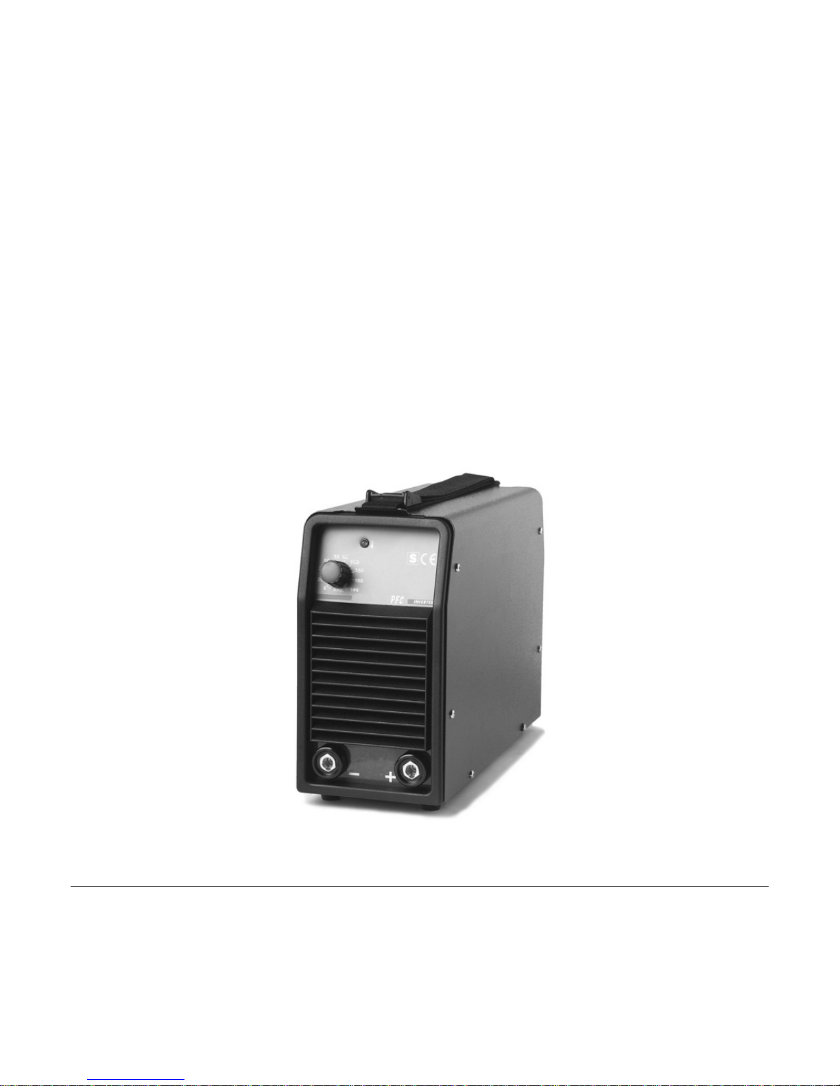
1 DESCRIZIONI GENERALI
Accertarsi che non sia limitato in alcun modo il flusso dell'aria
di raffreddamento e in particolare:
1.1 DESCRIZIONE DATI TECNICI
1) estrarre l'apparecchio dall'imballo,
2) evitare di appoggiarlo a pareti o di porlo, comunque, in
situazioni tali da limitare il flusso d’aria attraverso le feritoie
di ingresso e di uscita. Es. evitare copertura con teli,
stracci, fogli di carta, nylon, ecc.
3) assicurarsi che l'aria aspirata sia a temperatura inferiore a
40 gradi centigradi.
4) non collocare nessun dispositivo di filtraggio sui passaggi di
entrata aria della saldatrice.
La garanzia é nulla qualora venga utilizzato un qualsiasi tipo di
dispositivo di filtraggio.
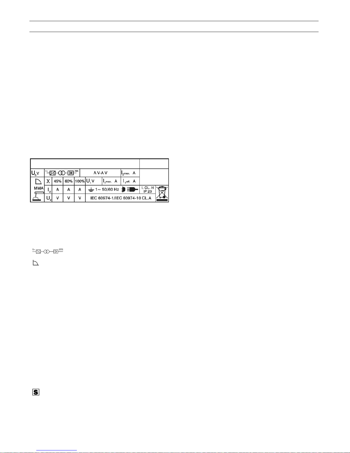
IEC 60974-1............ La saldatrice é costruita secondo
IEC 60974-10 queste norme internazionali.
Cl.A Apparecchiatura per uso industriale e
professionale.
2 INSTALLAZIONE
Art. ........................... Articolo della macchina che deve
essere sempre citato per qualsiasi
richiesta relativa alla saldatrice.
2.1 ALLACCIAMENTO ALLA RETE
Prima di effettuare l'allacciamento della macchina alla rete
verificare che la tensione di alimentazione sia quella indicata
nei dati di targa.
....... Convertitore statico di frequenza
monofase trasformatore-raddrizzatore.
2.2 PROTEZIONI
.......................... Caratteristica discendente.
Quest’apparecchio dispone di diverse protezioni interne che ne
assicurano sempre un corretto funzionamento:
MMA......................... Adatto per saldatura con elettrodi
rivestiti.
2.2.1 Protezione antincollaggio dell’elettrodo.
U
o............................. Tensione a vuoto secondaria.
Quando l'elettrodo si incolla sul pezzo, la macchina porta la
corrente I
2
a valori non pericolosi per l'elettrodo stesso. Questa
operazione è evidenziata dall’accensione del LED A fig. 1.
X.............................. Fattore di servizio percentuale.
Il fattore di servizio esprime la
percentuale di 10 minuti in cui la
saldatrice può lavorare ad una
determinata corrente senza causare
surriscaldamenti.
2.2.2 Protezioni termiche
Se intervengono (accensione LED A fig. 1), é necessario
attendere qualche minuto per avere il ripristino
dell’apparecchio.
I
2
.............................. Corrente di saldatura.
SOVRA-TENSIONI POSSONO DANNEGGIARE L'APPARECCHIO
U
2
............................. Tensione secondaria con corrente di
saldatura I
2
.
2.2.3 Protezione contro errate tensioni di alimentazione
U
1
............................. Tensione nominale di alimentazione.
Quando si accende l’interruttore (G fig. 1), se la tensione è
superiore a 270V, il led giallo (A fig. 1) lampeggia con due
lampi veloci intervallati da una pausa e la macchina non eroga
corrente.
1 ~ 50/60Hz............. Alimentazione monofase 50 oppure
60Hz.
I1 max........................ E’ il massimo valore della corrente
assorbita.
In questa situazione i circuiti elettrici sono protetti ma il
ventilatore, dopo pochi minuti può bruciare.
I1 eff………………… E’ il massimo valore della corrente
effettiva assorbita considerando il
fattore di servizio.
Durante la saldatura, se la tensione è bassa, il led giallo (A fig.
1) lampeggia con frequenza 0,5 secondi e la macchina non
eroga corrente.
IP23........................ Grado di protezione della carcassa.
Grado 3 come seconda cifra significa
che questo apparecchio è idoneo a
lavorare all'esterno sotto la pioggia.
2.2.4 Motogeneratori
Debbono avere un dispositivo di regolazione elettronico della
tensione, una potenza uguale o superiore a 5 kVA (per l’art.
145), 5,5 kVA (per l’art. 147) e non debbono erogare una
tensione superiore a 260V RMS.
.......................... Idonea a lavorare in ambienti con
rischio accresciuto di scosse elettriche.
3
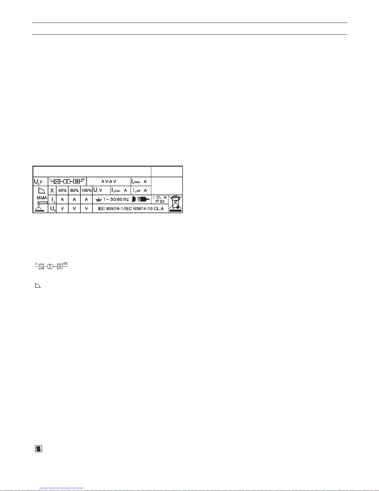
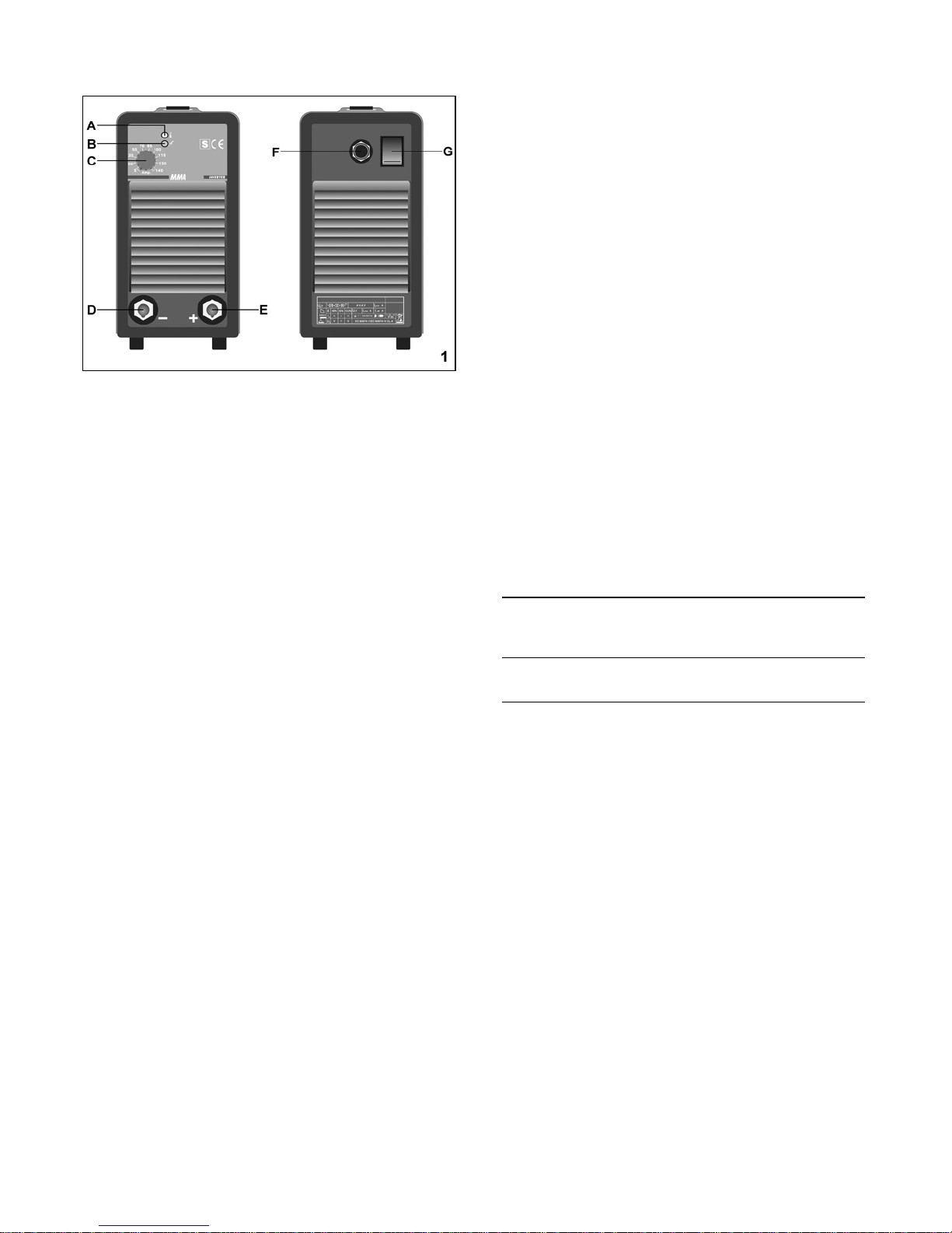
2.3 DESCRIZIONE DELL' APPARECCHIO
A) Segnalazione di intervento termostato e antincollaggio dello
elettrodo.
B) LED macchina alimentata.
C) Potenziometro regolazione corrente di saldatura.
D) e E) Innesti texas.
F) Cavo rete.
G) Interruttore generale di rete.
2.4 NOTE GENERALI
Prima dell'uso di questa saldatrice leggere attentamente le
norme CEI 26/10 - CENELEC HD 427 inoltre verificare
l'integrità dell'isolamento dei cavi, delle pinze porta elettrodi,
delle prese e delle spine e che la sezione e la lunghezza dei
cavi di saldatura siano compatibili con la corrente utilizzata:
fino a 5 m utilizzare 16 mm
2
;
da 5 a 20 m utilizzare 25 mm2;
da 20 a 30 m utilizzare 35 mm2.
2.5 SALDATURA DI ELETTRODI RIVESTITI
- Utilizzare pinze porta elettrodi rispondenti alle vigenti norme
di sicurezza e senza viti di serraggio sporgenti.
- Assicurarsi che l'interruttore (G fig. 1) sia sulla posizione O o
che la spina del cavo di alimentazione non sia inserita nella
presa di alimentazione quindi collegare i cavi di saldatura
rispettando la polarità richiesta dal costruttore di elettrodi che
andrete ad utilizzare.
- Il circuito di saldatura non deve essere posto
deliberatamente a contatto diretto o indiretto con il conduttore
di protezione se non nel pezzo da saldare.
- Se il pezzo in lavorazione viene collegato deliberatamente a
terra attraverso il conduttore di protezione, il collegamento
deve essere il più diretto possibile ed eseguito con un
conduttore di sezione almeno uguale a quella del conduttore
di ritorno della corrente di saldatura e connesso al pezzo in
lavorazione nello stesso punto del conduttore di ritorno
utilizzando il morsetto del conduttore di ritorno oppure
utilizzando un secondo morsetto di massa posto
immediatamente vicino.
- Ogni precauzione deve essere presa per evitare correnti
vaganti di saldatura.
- Quando si preleva tensione da una linea trifase occorre
molta attenzione nel collegare il filo di terra del cavo di
alimentazione al polo di terra della presa.
- Collegare il cavo di alimentazione. Quando si monta una
spina assicurarsi che questa sia di portata adeguata e che il
conduttore giallo/verde del cavo di alimentazione sia
collegato allo spinotto di terra.
- Eventuali prolunghe debbono essere di sezione adeguata
alla corrente I
1
assorbita.
- Accendere la macchina mediante l'interruttore (G fig. 1).
ATTENZIONE: LO SHOCK ELETTRICO PUÒ UCCIDERE!
- Non toccare parti sotto tensione.
- Non toccare i morsetti di uscita di saldatura quando
l'apparecchio é alimentato.
- Non toccare contemporaneamente la pinza porta elettrodo
ed il morsetto di massa.
- Regolare la corrente in base al diametro dell'elettrodo, alla
posizione di saldatura e al tipo di giunto da eseguire.
Terminata la saldatura ricordarsi sempre di spegnere
l'apparecchio e di togliere l'elettrodo dalla pinza porta
elettrodo.
2.6 SALDATURA TIG
- Questa saldatrice é idonea per saldare con procedimento
TIG: l'acciaio inossidabile, il ferro, il rame.
- Collegare il connettore del cavo di massa al polo positivo (+)
della saldatrice e il morsetto al pezzo nel punto più vicino
possibile alla saldatura assicurandosi che vi sia un buon
contatto elettrico.
- Collegare il connettore della torcia TIG al polo negativo (-)
della saldatrice.
- Il circuito di saldatura non deve essere posto deliberatamente a contatto diretto o indiretto col conduttore di
protezione se non nel pezzo da saldare.
- Se il pezzo in lavorazione viene collegato deliberatamente a
terra attraverso il conduttore di protezione, il collegamento
deve essere il più diretto possibile ed eseguito con un
conduttore di sezione almeno uguale a quella del conduttore
di ritorno della corrente di saldatura e connesso al pezzo in
lavorazione nello stesso punto del conduttore di ritorno,
utilizzando il morsetto del conduttore di ritorno oppure
utilizzando un secondo morsetto di massa posto
immediatamente vicino.
- Ogni precauzione deve essere presa per evitare correnti
vaganti di saldatura.
- Collegare il tubo gas all'uscita del riduttore di pressione
collegato ad una bombola di ARGON.
- Utilizzare un elettrodo di tungsteno toriato 2% scelto secondo
la tabella seguente:
ø elettrodo corrente continua
tungsteno 2% torio elettrodo negativo
(banda rossa) (Argon)
ø 1 mm (0,040") fino a 60A
ø 1,6 mm (1/16") 60 : 160A
- Controllare che la tensione di alimentazione corrisponda alla
tensione indicata sulla targa dei dati tecnici della saldatrice.
- Collegare il cavo di alimentazione: quando si monta una
spina assicurarsi che questa sia di portata adeguata e che il
conduttore giallo/verde del cavo di alimentazione sia
collegato allo spinotto di terra.
- Eventuali prolunghe debbono essere di sezione adeguata alla
corrente I
1
assorbita.
ATTENZIONE: LO SHOCK ELETTRICO PUO' UCCIDERE
- Non toccare parti sotto tensione.
- Non toccare i morsetti di uscita di saldatura quando
l'apparecchio é alimentato.
- Non toccare contemporaneamente la torcia e il morsetto di
massa.
- Accendere la macchina mediante l'interruttore (G fig. 1).
- Regolare la corrente in base al lavoro da eseguire quindi
aprire la valvola posta sulla torcia per consentire al gas di
uscire. Innescare, per contatto, l'arco con un movimento
deciso e rapido.
N.B. Non utilizzare dispositivi di accensione commerciali!
Terminata la saldatura ricordarsi di spegnere l'apparecchio e
chiudere la valvola della bombola del gas.
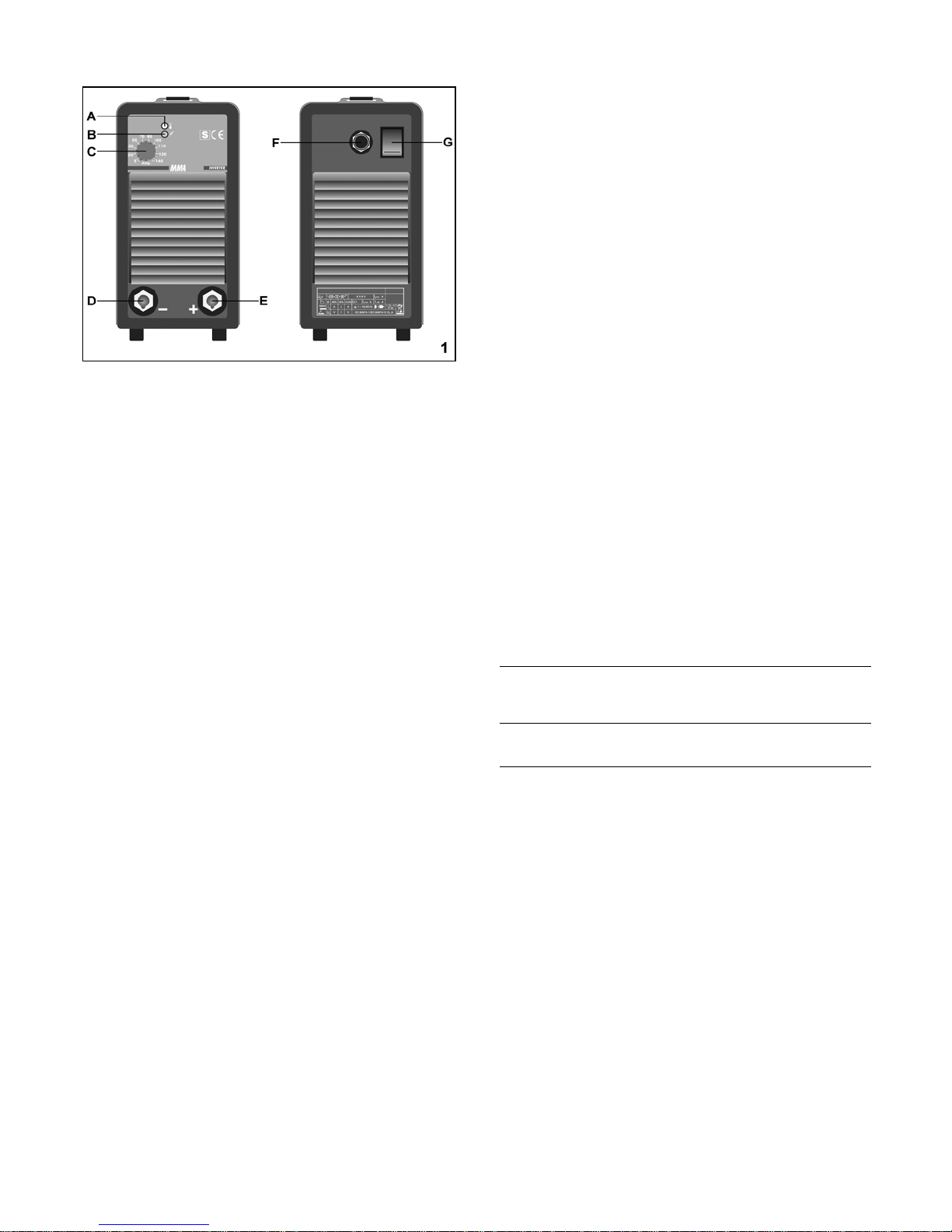
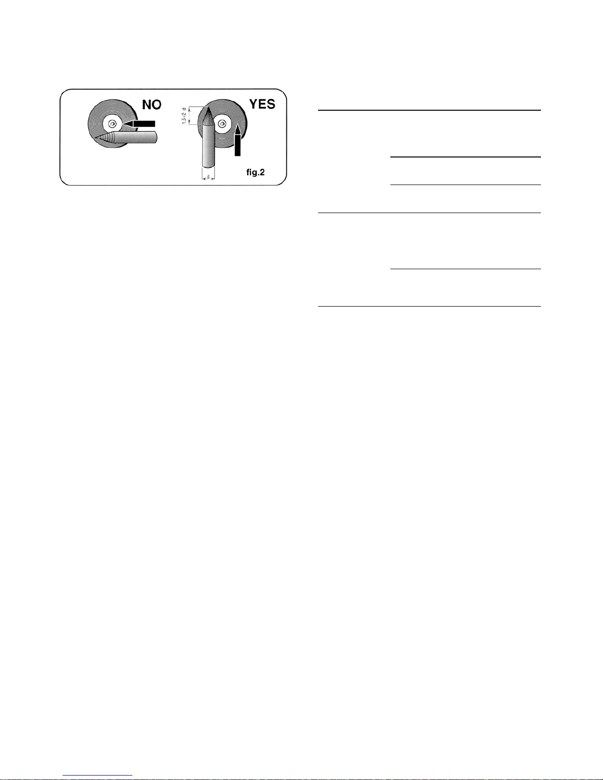
2.6.1 Preparazione dell'elettrodo
E' necessaria una particolare attenzione nella preparazione
4
della punta dell'elettrodo, smerigliarla in modo che presenti
rigatura verticale come indicato in fig. 2.
Esercitare solo pressioni minime e movimenti delicati ogni
volta che si collegano o scollegano i connettori della scheda o
si rimuove o si installa la scheda.
UN'ERRATA INSTALLAZIONE o connettori non allineati
possono danneggiare la scheda.
Accertarsi che i connettori siano opportunamente installati ed
allineati prima di installare nuovamente il fascione.
3.3 DIFETTI E RIMEDI
Difetto Probabile causa Rimedio
AVVERTENZE: PARTICELLE METALLICHE VOLATILI
INCANDESCENTI possono ferire il personale; originare
incendi e danneggiare le attrezzature, LA CONTAMINAZIONE
DA TUNGSTENO può abbassare la qualità della saldatura.
La saldatrice non Interruttore in posi- Posizionarlo su
eroga corrente; zione O I
completamente
inoperativa
− Sagomare l'elettrodo di tungsteno unicamente con una
smerigliatrice provvista di adeguati carter di protezione in
una zona sicura indossando opportune protezioni per il
viso, le mani ed il corpo.
Fusibili bruciati Sostituirli
Spina non perfet- Inserire la spina
− Sagomare gli elettrodi di tungsteno con una mola abrasiva
dura a grana fine, utilizzata unicamente per sagomare il
tungsteno.
tamente inserita nel-
la presa di alimen-
tazione
− Smerigliare l'estremità dell'elettrodo di tungsteno in forma
conica per una lunghezza di 1,5 - 2 volte il diametro
dell'elettrodo (fig. 2).
___
La saldatrice non Tensione di alimenta- Vedi 2.2.3
eroga corrente ma zione non corretta:
il ventilatore funzio- spia gialla accesa
3 MANUTENZIONE E CONTROLLI
na
3.1 NOTE GENERALI
___
Termostato aper- Attendere circa
to, spia blocco 5/6 minuti
ATTENZIONE: LO SHOCK ELETTRICO PUÒ UCCIDERE
gialla accesa
- Non toccare parti elettriche sotto tensione.
- Spegnere la saldatrice e togliere la spina di alimentazione
dalla presa prima di ogni operazione di controllo e
manutenzione.
LE PARTI IN MOVIMENTO possono causare lesioni gravi.
- Tenersi lontano da parti in movimento.
SUPERFICI INCANDESCENTI possono causare bruciature
gravi.
- Lasciar raffreddare la saldatrice prima di procedere alle
manutenzioni.
3.2 RIPARAZIONI DELLE SALDATRICI
L'esperienza ha dimostrato che molti incidenti mortali sono
originati da riparazioni non eseguite a regola d'arte. Per questa
ragione un attento e completo controllo su di una saldatrice
riparata é altrettanto importante quanto quello eseguito su una
saldatrice nuova.
Inoltre in questo modo i produttori possono essere protetti
dall'essere ritenuti responsabili di difetti, quando la colpa é da
imputare ad altri.
3.2.1. Prescrizione da eseguire per le riparazioni
- Dopo il riavvolgimento del trasformatore o delle induttanze la
saldatrice deve superare le prove di tensione applicata
secondo quanto indicato in tabella 4 della norma EN 60974-
1.
- Se non é stato effettuato alcun riavvolgimento, una saldatrice
che sia stata pulita e/o revisionata deve superare una prova
di tensione applicata con valori delle tensioni di prova pari al
50% dei valori dati in tabella 4 della norma EN 60974-1.
- Dopo il riavvolgimento e/o la sostituzione di parti la tensione a
vuoto non deve superare i valori esposti in 11.1 di EN60974-
1.
- Se le riparazioni non sono eseguite dal produttore, le
saldatrici riparate nelle quali siano stati sostituiti o modificati
alcuni componenti, devono essere marcate in modo che
possa essere identificato chi ha compiuto la riparazione.
3.2.2 Accorgimenti da utilizzare durante un intervento di
riparazione
UNA PRESSIONE ECCESSIVA può provocare rotture delle
schede elettroniche.

5
INSTRUCTION MANUAL FOR ARC WELDING MACHINE
IMPORTANT
Before using this device all people authorised to its use, repair
or inspection, should read the book "Safety rules for using
machines" and the "Instruction manual" specific for every
machine. Contact your distributor if you have not understood
some instructions.
It is also essential to pay special attention to the "SAFETY
RULES" Manual. The symbols next to certain paragraphs
indicate points requiring extra attention, practical advice or
simple information.
This MANUAL and the "SAFETY RULES" MANUAL must be
stored carefully in a place familiar to everyone involved in
using the machine. They must be consulted whenever doubts
arise and be kept for the entire lifespan of the machine; they
will also be used for ordering replacement parts.
IN CASE OF MALFUNCTIONS, REQUEST ASSISTANCE
FROM QUALIFIED PERSONNEL.
1 GENERAL DESCRIPTIONS
1.1 EXPLANATION OF TECHNICAL SPECIFICATIONS
IEC 60974-1 The welder is manufactured according
IEC 60974-10......... to these international standards.
Cl. A........................ Machine for professional and industrial
use.
Art............................ Item number that must be stated for
any demands relating to the welding
machine.
.... Single-phase static frequency con-
verter - transformer - rectifier.
.......................... Dropping characteristic.
MMA....................…. Suitable for manual welding with coated
electrodes.
Uo............................. Secondary no - load voltage.
X.............................. Duty – cycle percentage.
The duty-cycle expresses the per-
centage, calculated on 10 minutes, in
which the welding machine can operate
at a determined current, without over-
heating.
I2.............................. Welding current.
U
2
............................. Secondary voltage with I2 welding
current.
U1............................. Nominal supply voltage.
1 ~ 50/60Hz............. Single - phase supply 50 or 60 Hz.
I1 max. …………….. This is the maximum value of the
absorbed current
I
1
eff........................ This is the maximum value of the actual
current absorbed, considering the duty
cycle.
IP23....................... Grade of protection of frame. Grade 3
as a second number means that this
unit is fit to work outside under the rain.
......................... Symbol meaning that the welding
machine can be used in high electric
shock risk-working areas.
NOTES:..................... In addition, the welding machine has
been designed to work in areas with
grade 3 of pollution.(See IEC 664).
1.2 SPECIFICATIONS
This welding machine is a constant direct current generator,
created by the INVERTER technology, designed for welding
with coated electrodes and with the TIG procedure.
For any requests of information, please always state the item
and the serial number of the welding machine.
1.3 BEFORE CONNECTING THE WELDING MACHINE
Before connecting and switching on the unit follow all safety
rules and instructions as indicated in this manual. Make sure
that the airflow on cooling slots is not obstructed and then
proceed as follows:
1) unpack the machine
2) take care that the unit is not placed against a wall or in a
position that might cut off the air; moreover, do not cover
the unit's source with plastic materials, metal or paper
sheets because they cause the decrease of the airflow,
3) make sure that the air temperature does not exceed +40°C,
4) do not place any filtering device over the intake air
passages of this welding machine.
Warranty is void if any type of filtering device is used.
2 INSTALLATION
2.1 CONNECTION TO MAINS SUPPLY
Before connecting the unit to the mains make sure that supply
voltage corresponds to the voltage indicated on the welding
machine technical specification tag.
2.2 PROTECTION SYSTEM
The unit is equipped with internal protections, which assure a
lasting proper operation.
These protective systems are the following:
2.2.1 Electrode anti-sticking protection
When the electrode sticks itself on the piece, the machine
brings the I
2
current to not dangerous values for the electrode.
The signal light A (picture 1) indicates this operation.
2.2.2 Thermal protections
The signal light A (picture 1) indicates the intervention of this
protection. As soon as the unit has cooled down, it will be in
working conditions again.
OVER VOLTAGE CAN DAMAGE THE UNIT
2.2.3 Protection against incorrect supply voltages
If the voltage is greater than 270V when the switch (G pict. 1)
is turned on, the yellow led (A pict. 1) will flash briefly twice,
with a brief pause between flashes, and the machine will not
deliver current.
In this situation the electric circuits are protected, but the fan
may burn out after a few minutes.
In the voltage low during welding, the yellow led (A pict. 1)
flashes every 0.5 seconds and the machine does not deliver
current.
2.2.4 Motor-driven generators
They must have an electronic regulator of the tension, a power
equal to or greater than 5 kVA (for art. 145), 5,5 kVA (for art.
147), and must not deliver a voltage greater than 260V RMS.
6
2.3 UNIT DESCRIPTION
A) Thermal and electrode anti-sticking protections signal.
B) Power On signal.
C) Welding current adjustment potentiometer.
D) and E) Texas connections.
F) Power supply cable.
G) Input voltage general switch.
2.4 GENERAL NOTES
Before using this welding machine, carefully read the
standards CEI 26/10 CENELEC HD 427 and also check
insulation of cables, electrode holder clamp, sockets and plugs
and that the section and length of welding cables are
compatible with current used:
up to 5 m use 16 mm
2
,
from 5 to 20 m use 25 mm2,
from 20 to 30 m use 35 mm2.
2.5 COATED ELECTRODE WELDING
- Use the electrode holder clamps in compliance with the
safety standards and without projecting tightening screws.
- Make sure that the switch G (picture 1) is in O position or that
the plug is not inserted in supply socket then connect welding
cables in accordance with polarity demanded by the
manufacturer of the electrodes which you will be using.
- W elding circuit should not be deliberately placed in direct or
indirect contact with protection wire if not in the piece to be
weld.
- If earthing is deliberately made on the workpiece by means
of the protection wire, the connection must be as direct as
possible, with the wire having a section at least equal to the
welding return current wire and connected to the piece,
being worked on, in the same place as the return wire, using
the return wire terminal or a second earth terminal close by.
- All possible precautions must be taken in order to avoid stray
currents.
- When taking voltage from a three-phase line, be very
careful when connecting the supply cable earth wire to
the socket earth pole.
- Connect the supply cable. When mounting a plug, make sure
that its capacity is adequate and that the yellow-green wire of
the supply cable is connected to the earth plug pin.
- The sections of all extensions should be adequate to
absorbed current I
1
.
- T urn the machine on by means of the switch G (picture 1).
WARNING: ELECTRIC SHOCK CAN KILL.
- Do not touch live electric parts.
- Do not touch weld output terminals when unit is energized.
- Do not touch electrode holder and earth clamp at the same
time.
- Adjust the current according to the diameter of the electrode,
to the welding position and to the type of joint to be carried
out.
When you have finished to weld, always remember to turn off
the unit and to remove the electrode from the electrode
holder.
2.6 TIG WELDING
- This welding machine is fit for welding with TIG procedure:
stainless steel, iron and copper.
- Connect the earth cable wire to the positive (+) pole of the
welding machine and the terminal to the working piece as
close as possible to the welding machine, making sure there
is a good electrical contact.
- Connect the connector of the TIG torch to the negative (-)
pole of the welding machine.
- The welding machine circuit should not be deliberately in
direct or indirect contact with protection conductor if not in the
piece to be welded.
- If earthing is deliberately made on the workpiece by means of
protection wire, the connection must be as direct as possible,
with the wire having a section at least equal to the welding
return current wire and connected to the piece being worked
on, in the same place as the return wire, using the return wire
terminal or a second earth terminal close by.
- All possible precautions must be taken in order to avoid stray
currents.
- Connect gas pipe to pressure reducer output connected to an
ARGON cylinder.
- Use a 2% thoriated tungsten electrode chosen according to
table.
electrode ø direct current
2% thoriated tungsten negative electrode
(red band) (Argon)
ø 1 mm (0,040") up to 60A
ø 1,6 mm (1/16") 60 ÷ 160A
- Make sure that mains voltage corresponds to the voltage of
the welding machine.
- Connect the supply cable: when mounting a plug, make sure
that its capacity is adequate and that the yellow-green wire of
the supply cable is connected to the earth plug pin.
- Any extensions should have adequate sections for absorbed
current
I
1
.
WARNING: ELECTRIC SHOCK CAN KILL!
- Do not touch live electric parts.
- Do not touch weld output terminals when unit is energized.
- Do not touch torch and earth clamp at the same time.
- Turn on the machine on with switch G (picture 1).
- Regulate current according to the work to be carried out, then
open the valve placed on the torch to allow the emission of
gas. Start the arc by contact, with a determined rapid
movement.
CAUTION: do not use commercial ignition devices.
When you have finished to weld, always remember to turn off
the machine
and to close the gas cylinder valve.
7
2.6.1 Electrode preparation
It is necessary to pay special attention to the preparation of the
electrode point, grinding it so as to obtain vertical markings as
shown in picture 2.
CAUTION: HOT FLYING METAL PARTICLES can injure
persons, start fires and damage equipment. TUNGSTEN
CONTAMINATION can lower the welding quality.
- Shape tungsten electrode only on grinder with proper guards
in a safe location, wearing proper face, hand, and body
protections.
- Shape tungsten electrodes on a fine grit, hard abrasive wheel
used only for tungsten shaping.
- Grind the end of the tungsten electrode to a taper-shape for a
length of 1,5 -2 electrode diameters (picture 2).
3 MAINTENANCE AND CHECK UP
3.1 GENERAL NOTES
WARNING: ELECTRIC SHOCK CAN KILL.
- Do not touch live electrical parts.
- Turn off welding power source and remove input power plug
from socket before maintenance and servicing.
MOVING PARTS can cause serious injury.
- Keep away from moving parts.
HOT SURFACES can cause severe burns.
- Allow the cooling of the unit before servicing.
3.2 WELDING MACHINE MAINTENANCE
Experience has shown that many fatal accidents originated
from servicing which had not been perfectly executed. For this
reason, a careful and thorough inspection on a serviced
welding machine is just as important as one carried out on a
new welding machine.
Furthermore, in this way manufacturer can be protected from
being held responsible for defects when the fault is someone
else.
3.2.1 Prescriptions to follow for servicing:
- After rewinding the transformer or the inductance, the welding
machine must pass the voltage test applied according to that
indicated in table 4 of the EN 60974-1.
- If no rewinding is done, a welding machine which has been
cleaned and/or reconditioned must pass a voltage test
applied with voltage values equal to 50% of the values given
in table 4 of EN 60974-1.
- After rewinding and/or the replacements of parts, the no-load
voltage should not exceed the values given in 11.1 of EN
60974-1.
- If the servicing is not done by the manufacturer, the repaired
welding machines which underwent replacements or
modifications of any component should be labelled in a way
such that the identity of the person having serviced is clear.
3.2.2 Precautions to take while servicing:
AN EXCESSIVE PRESSURE can break the circuit board.
Use only minimal pressure and gentle movements when
disconnecting or connecting board plugs and removing or
installing board.
INCORRECT INSTALLATION or misaligned plugs can
damage circuit boards.
Check that plugs are properly installed and aligned before
reinstalling the cover.
3.3 TROUBLE SHOOTING
DEFECT PROBABLE CAUSE REMEDY
The welding Switch in O position Switch to I
machine does not position
supply current;
completely
inoperative
Burnt fuses Replace
fuses
Plug not correctly Connect it
connected properly
_____
The welding Incorrect supply See 2.2.3
machine does voltage: yellow
not supply current signal lights up
but the ventilator
works
_____
Thermostat is open. Wait approx.
Yellow block signal 5-6 min.
lights up.
8
BETRIEBSANLEITUNG FÜR LICHTBOGENSCHWEISSMASCHINEN
WICHTIG
Lesen Sie bitte vor der Installation, Benützung oder Wartung
der Maschinen den Inhalt des Buches
"Sicherheitsvorschriften für die Benützung der
Maschinen" und des "Anleitungshandbuches" spezifisch
für jede Maschinen mit Aufmerksamkeit. Falls Sie fragen
haben, wenden Sie sich bitte an Ihren Fachhändler.
Des weiteren ist dem Handbuch, das die
Sicherheitsvorschriften enthält, größte Beachtung zu
schenken. Die Symbole neben den einzelnen Paragraphen
weisen auf Situationen, die größte Aufmerksamkeit verlangen,
Tipps oder einfache Informationen hin.
Die beiden Handbücher sind sorgfältig an einem Ort
aufzubewahren, der allen Personen, die mit dem Gerät zu tun
haben, bekannt ist. Sie sind immer dann heranzuziehen, wenn
Zweifel bestehen. Die beiden Handbücher haben die Maschine
über ihre ganze Lebensdauer zu “begleiten” und sind bei der
Bestellung von Ersatzteilen heranzuziehen.
1 ALLGEMEINE BESCHREIBUNGEN
1.1 ERKLÄRUNGEN UND TECHNISCHE ANGABEN
IEC 60974-1...... Die Schweißmaschine wurde nach diesen
IEC 60974-10...... internationale Normen gebaut.
Cl. A..................... Maschine für den industriellen und den
professionellen Einsatz
Art. ...................... Artikel Nr. ; diese muß bei allen Anfragen,
die Schweißmaschine betreffen, genannt
werden.
.. Einphasig Umrichter - Trafo - Gleichrichter.
..…............. Absteigende Kennlinie.
MMA................... Eignet sich für Schweißungen mit
beschichteten Elektroden.
Uo....................... Sekundär - Leerlaufspannung.
X................…..... Betriebsfaktor Prozentsatz.
Der Betriebsfaktor drückt den Prozentsatz
der jenigen Zeitspanne innerhalb von 10
Minuten aus, in der die Schweißmaschine
bei einem bestimmten Stromwert laufen
kann, ohne sich überhitzen.
I2......................... Schweißstrom.
U
2
........................ Sekundärspannung bei Schweiß-strom I2.
U1........................ Nennspannung der Stromversorgung.
1 ~ 50/60Hz........ Einphasige Speisung 50 oder 60Hz.
I
1
max. ………… Dies ist der Höchstwert der
Stromaufnahme.
I1 eff. ………….. Dies ist der Höchstwert der effektiven
Stromauf-nahme bei Berücksichtigung der
relativen Einschaltdauer.
IP 23................... Schutzgrad des Gehäuses. Grad 3 als
zweite Zahl bedeutet, daß dieser Apparat
für Außenarbeiten bei Regen geeignet ist.
.................... Eignet sich für Arbeiten in Zonen, in denen
das Risiko erhöht ist.
BEMERKUNGEN: Die Schweißmaschine eignet sich zu dem
für Einsätze in Gebieten, in denen der
Verschmutzungsgrad die Stufe 3 erreicht
hat (siehe IEC 664).
1.2 SPEZIFIKATIONEN
Diese Schweißmaschine erzeugt konstanten Gleichstrom und
wurde anhand der INVERTER - Technologie geschaffen. Sie
ist dazu bestimmt, mit umhüllten Elektroden oder im WIG Verfahren zu schweißen.
Sollten Sie Fragen zu dem Schweißgerät haben, bitten wir Sie
um Angabe der Artikel und Seriennummer.
1.3 VORBEREITENDE MASSNAHMEN
Bevor man das Gerät an das Stromnetz anschließt und es in
Betrieb setzt, sind einige einfache Vorschriften zu beachten.
Auch wenn diese sehr einleuchtend sind, könnten sie doch
gegebenenfalls übergangen werden. Zuerst ist sicherzustellen,
daß der Kühlluftstrom auf keinerlei Weise beeinträchtigt ist.
1. Das Gerät aus der Packung herausnehmen.
2. Nicht an die Wand rücken bzw. nie so aufstellen, daß der
Luftstrom durch die Eingangs- und Ausgangsschlitze
behindert wird. Es darf z.B.; nicht mit Tüchern, Papier
oder Nylon usw. abgedeckt werden.
3. Es ist sicherzustellen, daß die Temperatur der
angesaugten Luft weniger als 40°C beträgt.
4. Keine Filter an den Lufteinlaßöffnungen anbringen.
Beim Einsatz von Filtervorrichtungen verfällt der
Garantieanspruch.
2 INSTALLATION
2.1 NETZANSCHLUSS
Bevor man das Gerät an das Netz anschließt, ist zu
überprüfen, ob die Versorgungsspannung mit den Angaben
auf dem Schild übereinstimmt.
2.2 SCHUTZVORRICHTUNGEN
Dieses Gerät verfügt über verschiedene interne
Schutzvorrichtungen, die jederzeit einen einwandfreien Betrieb
gewährleisten.
2.2.1 Schutz gegen das Festkleben der Elektrode
Bei Festkleben der Elektrode am Werkstück regelt das Gerät
den Strom I
2
auf Werte, durch die Elektrode nicht gefährdet
wird. Signallampe A (Abb. 1) weist diese Handlung.
2.2.2 Thermoschutzvorrichtungen
Die Signallampe A (Abb. 1) weist die Anwesenheit dieser
Schutzvorrichtung. Bevor man das Gerät wieder betreiben
kann, muß man einige Minuten verstreichen lassen.
ÜBERSPANNUNGEN KÖNNEN ZU SCHÄDEN AM GERÄT
FÜHREN
2.2.3 Schutz gegen falsche Speisespannungen
Wenn beim Einschalten von Schalter G (Abb. 1) die Spannung
über 270 V liegt, blinkt die gelbe led A (Abb. 1) (zweimal kurz
Aufleuchten – Pause – usw.) und die Maschine gibt keinen
Strom ab. In diesem Zustand sind die Stromkreise geschützt,
doch der Ventilator kann innerhalb von einigen Minuten
durchbrennen. Wenn die Spannung während des Schweißens
gering sinkt, blinkt die gelbe led A (Abb. 1) mit einer Frequenz
von 0,5 Sekunden und die Maschine gibt keinen Strom ab.
2.2.4 Generator - Aggregat
Seine Leistung muß größer oder gleich 5 kVA (für Art. 145),
5,5 kVA (für Art. 147) sein, es darf keine Spannung von mehr
als 260V RMS abgeben und darf über eine elektronische
Spannungregulierungsvorrichtung verfügen.
 Loading...