

Elettro MIG 176, MIG 270, MIG 225, MIG 190, MIG 200 Instruction Manual
...
IT MANUALE DI ISTRUZIONE PER SALDATRICE A FILO ......................... Pag. 3
EN INSTRUCTION MANUAL FOR WIRE WELDING MACHINE ................... Page 7
DE BETRIEBSANLEITUNG FÜR DRAHTSCHWEISSMASCHINEN ................ Seite 11
FR MANUEL D'INSTRUCTIONS POUR POSTES A SOUDER A FIL .............. Page 15
ES MANUAL DE INSTRUCCIONES PARA SOLDADORAS DE HILO ............. Pag. 19
PT
MANUAL DE INSTRUÇÕES PARA SOLDADORES A FIO ........................
Pag. 23
Parti di rica
mbio e schema elettrico
Spare parts and wiring diagram
Ersatzteile und elektrischer Schaltplan
Pièces de rechanges et schéma électrique
Partes de repuesto y esquema eléctrico
Peças e esquema eléctrico Pagg. Seiten 28
2
1
2
3
MANUALE D'ISTRUZIONE PER SALDATRICI A FILO
IMPORTANTE: PRIMA DELLA INSTALLAZIONE, DELL’USO O
DI QUALSIASI MANUTENZIONE ALLA SALDATRICE
LEGGERE IL CONTENUTO DI QUESTO MANUALE E DEL
MANUALE “REGOLE DI SICUREZZA PER L’USO DELLE
APPARECCHIATURE” PONENDO PARTICOLARE
ATTENZIONE ALLE NORME DI SICUREZZA. CONTATTARE
IL VOSTRO DISTRIBUTORE SE NON AVETE COMPRESO
COMPLETAMENTE QUESTE ISTRUZIONI.
Questo apparecchio deve essere utilizzato esclusivamente per
operazioni di saldatura. Non deve essere utilizzato per
scongelare tubi.
E’ inoltre indispensabile tenere nella massima considerazi one il
manuale riguardante le regole di sicurezza.
I simboli posti in prossimità dei paragrafi ai quali si riferiscono,
evidenziano situazioni di massima attenzione, consigli pratici o
semplici informazioni.
Entrambi i manuali devono essere conservati con cura, in un
luogo noto ai vari interessati. Dovranno essere consultati ogni
qual volta vi siano dubbi, dovranno seguire tutta la vita operativa
della macchina e saranno impiegati per l’ordinazio ne delle parti
di ricambio.
1 DESCRIZIONE GENERALE
1.1 SPECIFICHE
Questo manuale è stato preparato allo scopo di istruire il
personale addetto all'installazione, al funzionamento ed alla
manutenzione della saldatrice.
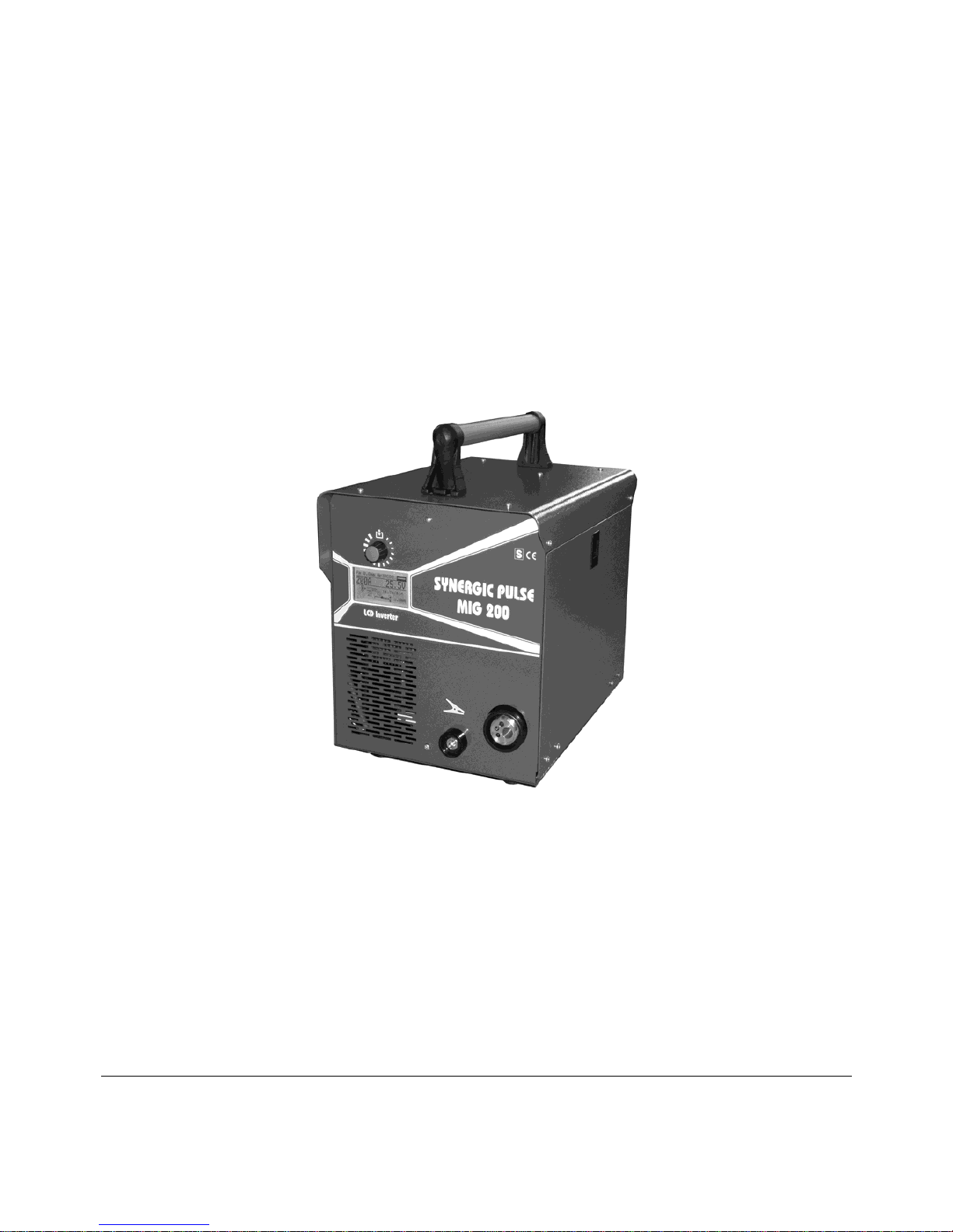
Questa saldatrice è un generatore realizzato con tecnologia
INVERTER, adatto alla saldatura MIG.
Controllare, al ricevimento, che non vi siano parti rotte o
avariate.
Ogni eventuale reclamo per perdite o danni deve essere fatto
dall'acquirente al vettore. Ogni qualvolta si richiedono
informazioni riguardanti la saldatrice, si prega di indicare
l'articolo ed il numero di matricola.
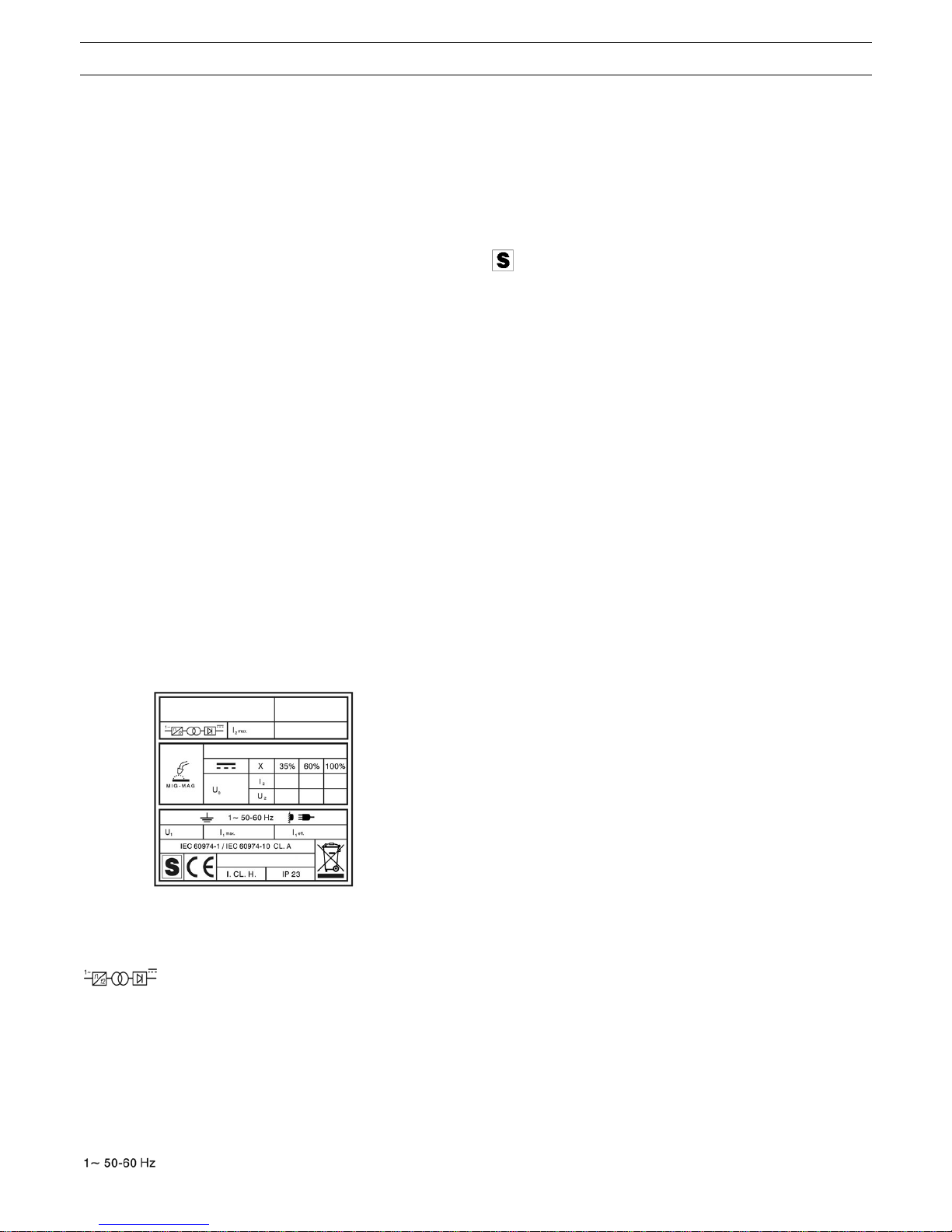
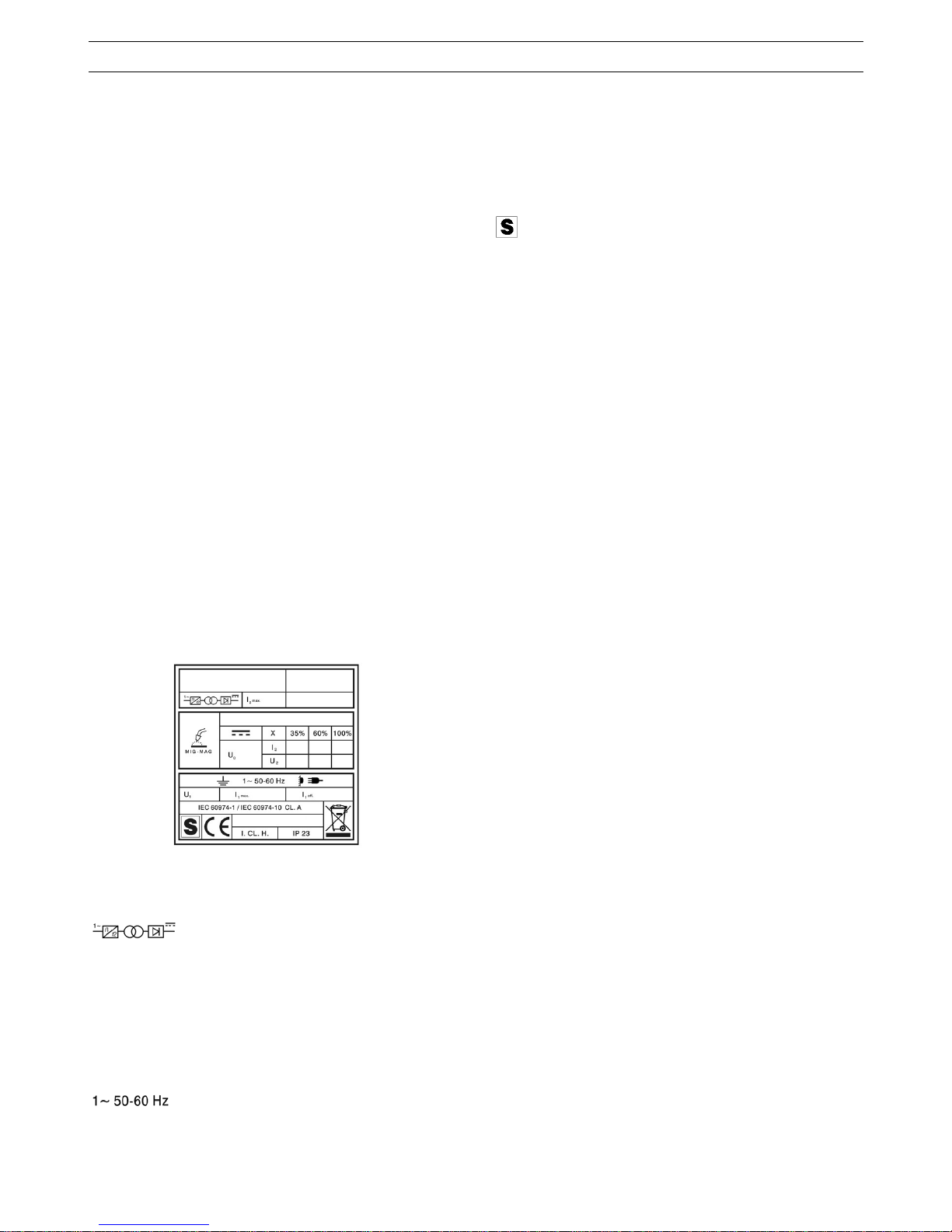
1.2 SPIEGAZIONE DEI DATI TECNICI
IEC609
74-1 La saldatrice è costruita secondo queste norme
IEC60974-10
CL.A Apparecchiatura per uso industriale e
professionale.
Convertitore statico di frequenza monofase
trasformatore raddrizzatore.
MIG-MAG Adatto per saldatura a filo continuo.
U0 Tensione a vuoto secondaria.
X Fattore di servizio percentuale. Il fattore di servizio
esprime la percentuale di 10 minuti in cui la
saldatrice può lavorare ad una determinata
corrente senza causare surriscaldamenti.
I
2
Corrente di saldatura
U
2
Tensione secondaria con corrente di sald. I2
U
1
Tensione nominale di alimentazione.
Alimentazione monofase 50 oppure 60 Hz.
I
1
max Corrente max. assorbita alla corrispondente
corrente I
2
e tensione U2.
I
1
eff E' il massimo valore della corrente effettiva
assorbita considerando il fattore di servizio.
Solitamente, questo valore corrisponde alla portata
del fusibile (di tipo ritardato) da utilizzare come
protezione per l’apparecchio.
IP23 Grado di protezione della carcassa.
Grado 3 come seconda cifra significa che
questo apparecchio è idoneo a lavorare
all’esterno sotto la pioggia.
Idonea a lavorare in ambienti con rischio
accresciuto.
NOTE: La saldatrice è inoltre stata progettata per lavorare in
ambienti con grado di inquinamento 3. (Vedi IEC 60664).
2 INSTALLAZIONE
L’installazione della macchina deve essere fatta da
personale qualificato.
Tutti i collegamenti devono essere eseguiti in conformità
delle vigenti norme e nel pieno rispetto della legge
antinfortunistica.
Controllare che la tensione di alimentazione corrisponda al
valore indicato sul cavo rete. Se non è già montata, col legare
una spina di portata adeguata al cavo di alimentazione
assicurandosi che il conduttore giallo/verde sia collegato allo
spinotto di terra.
La portata dell'interruttore magnetotermico o dei fusibili, in serie
all'alimentazione, devono essere uguale alla corrente I
1
max.
assorbita dalla macchina.
2.1 SISTEMAZIONE
Collocare la saldatrice in un ambiente ventilato. Polvere, sporco
o qualsiasi altra cosa estranea che possa entrare nella
saldatrice ne può compromettere la ventilazione e quindi il buon
funzionamento.
Pertanto è necessario in relazione all'ambiente e all e condizioni
di impiego avere cura di mantenere pulite le parti interne. La
pulizia deve avvenire tramite un getto di aria secca e pulita,
facendo attenzione a non danneggiare in alcun modo la
macchina. Prima di lavorare all'interno della saldatrice
assicurarsi che la spina sia staccata dalla rete di alimentazione.
Qualsiasi intervento eseguito all'interno della saldatrice deve
essere eseguito da personale qualificato.
2.2 PROTEZIONI
2.2.1 Protezione di blocco
In caso di malfunzionamento della saldatrice, sul display B può
comparire una scritta WARNING che identifica il tipo di difetto,
se spegnendo e riaccendendo la macchina la scritta rimane,
contattare il servizio assistenza.
2.2.2 protezione termica
Quest’apparecchio è protetto da un termostato il quale, se si
superano le temperature ammesse, impedisce il funzionamento
della macchina. In queste condizioni il ventilatore continua a
funzionare ed il display B visualizza, in modo lampeggian te, la
sigla WARNING tH.
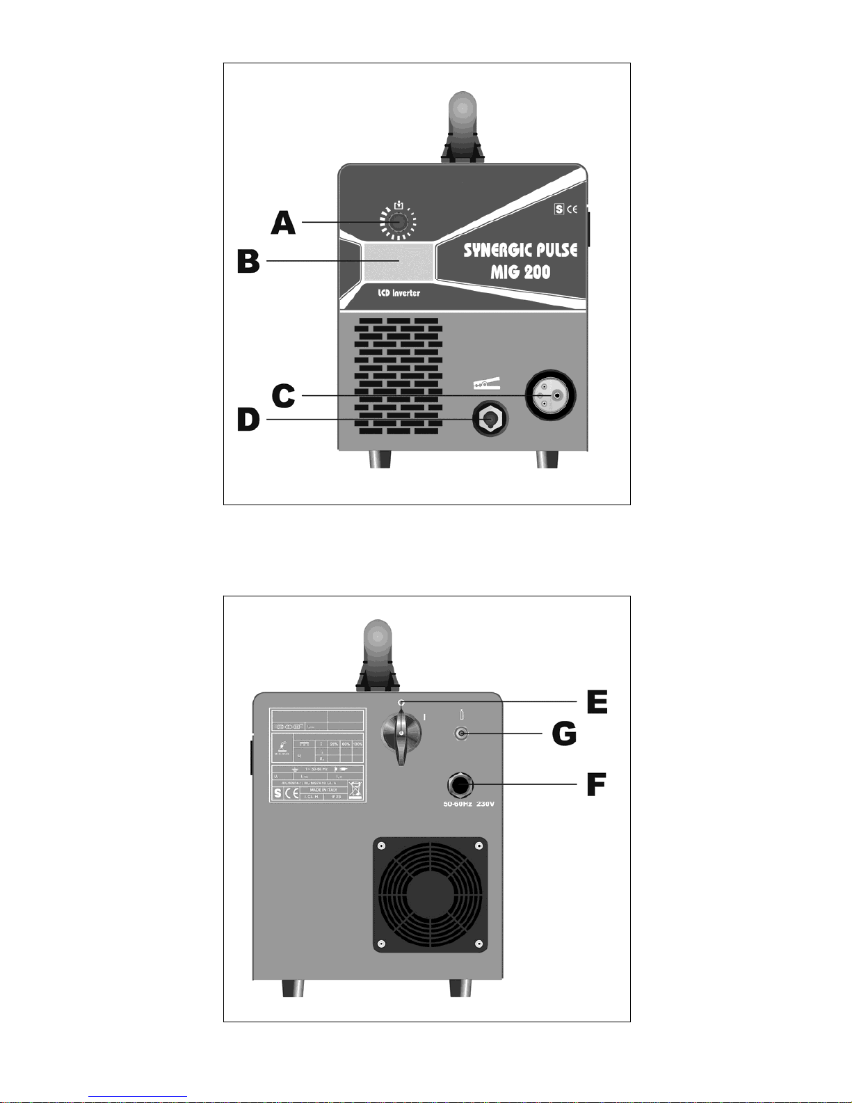
3 COMANDI POSTI SUL PANNELLO ANTERIORE (Fig. 1)
A - MANOPOLA
Seleziona e regola sia le funzioni che i parametri di
saldatura.
B - DISPLAY
Visualizza sia i parametri di saldatura che tutte le funzioni di
saldatura.
C - ATTACCO CENTRALIZZATO
A cui va collegata la torcia di saldatura.

4
D - CAVO MASSA O PRESA
A cui va collegato il connettore del cavo di massa
E - INTERRUTTORE
Accende e spegne la macchina
F - CAVO RETE
G - RACCORDO CON TUBO GAS
5 MESSA IN OPERA
Verificare che la tensione d’alimentazione corrisponda a quella
nominale della saldatrice.
Dimensionare i fusibili di protezione in base ai dati riportati sulla
targa dei dati tecnici
Collegare il tubo gas della saldatrice al riduttore di pressione
della bombola.
Montare la torcia MIG all’attacco C.
Collegare il cavo di massa alla presa D e il morsetto di massa al
pezzo da saldare.
Controllare che la gola dei rulli corris ponda al diametro del filo
utilizzato. Per la eventuale sostituzione: aprire lo sportello
laterale, montare la bobina del filo ed infilare il filo nel traino e
nella guaina della torcia. Bloccare i rulli premifilo con la
manopola e regolare la pressione.
Accendere la macchina.
Scegliere la curva sinergica adeguata, seguendo le istruzioni
descritte nel paragrafo
funzioni di servi
zio (PROCESS
PARAMS). Togliere l’ugello gas e svitare l’ugello portacorrente
dalla torcia. Premere il pulsante della torcia fino alla fuoriuscita
del filo. ATTENZIONE tenere il viso lontano dalla lancia
terminale mentre il filo fuoriesce, avvitare l’ugello
portacorrente e infilare l’ugello gas.
Aprire il riduttore della bombola e regolare il flusso del gas a 8 –
10 l/min.
Durante la saldatura il display B visualizza la corrente e la
tensione effettiva di lavoro, i valori visualizzati possono essere
leggermente diversi dai valori impostati, questo può dipendere
da molteplici fattori, tipo di torcia, spessore diverso dal nominale,
distanza tra ugello porta corrente e il materiale che si sta
saldando e la velocità di saldatura.
I valori di corrente e tensione, alla fine della saldatura rimangono
memorizzati sul display B dove compare la scritta HOLD, per
visualizzare i valori impostati è necessario ruotare le ggermente
la manopola A, mentre spingendo il pulsante torcia senza
saldare, sul display B compare il valore di tensione a vuoto e il
valore di corrente uguale a 0.
Se durante la saldatura si superano i valori massimi di corrente
e tensione, questi ultimi non rimangono memorizzati sul display
e la scritta HOLD non viene visualizzata.
NB. Se si utilizzano fili di diametro 0,6mm è consigliato sostituire
la guaina della torcia di saldatura con una di diametro interno
adeguato.
Una guaina con un diametro interno troppo grande non
garantisce una corretta scorrevolezza del filo di saldatura.
6 DESCRIZIONE FUNZIONI VISUALIZZATE SUL DISPLAY B
All’accensione della macchina il display B per qualche istante
visualizza: il numero di articolo della macchina, la versione, la data
di sviluppo del software, e il numero di release delle curve
sinergiche.
Subito dopo l’accensione il display B visualizza: la curva
sinergica utilizzata, il modo di saldatura 2T o 4T, la funzione
SPOT se attivata, il processo di saldatura SHORT o PULSATO
(opzionale), la corrente di saldatura, la velocità in metri al minuto
del filo di saldatura, la tensione di saldatura e lo spessore
consigliato.
Per aumentare o diminuire i parametri di saldatura è sufficiente
regolare tramite la manopola A, i valori cambiano tutti assieme,
in modo sinergico.
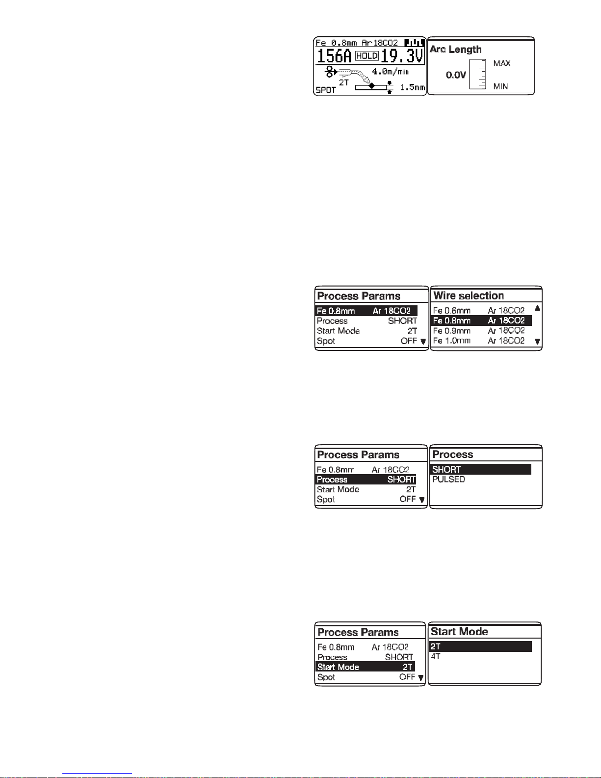
Per modificare la tensione di saldatura V è s ufficiente premere
per meno di 2 secondi la manopola A, sul display compare
(Arc Length o lunghezza d’arco) una barra di regolazione
con lo 0 centrale, il valore può essere modificato tramite la
manopola A d a -9,9 a 9,9 per uscire dalla funzione premere
brevemente la manopola A.
6.1 FUNZIONI DI SERVIZIO (PROCESS PARAMS)
VISUALIZZATE SUL DISPLAY B.
Per accedere a queste funzioni bisogna partire dalla schermata
principale e premere per almeno 2 secondi la manopola A.
Per entrare dentro la funzione è sufficiente selezionarla con la
manopola A e premer e la stessa per meno di 2 secondi.
Per ritornare alla schermata principale premere per almeno 2
secondi la manopola A.
Le funzioni selezionabili sono:
Curva sinergica (Wire Selection).
Per scegliere la curva sinergica, è necessario, tramite la
manopola A, selezion are e premere sulla curva pro posta dal
display B, è sufficiente selezionare la curva che ci interessa
e confermare la scelta premendo per meno di 2 secondi sulla
manopola A.
Dopo aver premuto la manopola A si ritorna alla schermata
precedente (PROCESS PARAMS).
Process
Per scegliere o confermare il tipo di saldatura, è necessario,
tramite la manopola A, selezionare e premer e, per meno di 2
secondi su Short o Pulsed (opzionale).
Short identifica che il tipo di saldatura scelto è short
sinergico.
Pulsed (opzionale) identifica che il tipo di saldatura scelto è
pulsato sinergico.
Modo di saldatura (Start Mode).
Modo 2T, la macchina inizia a saldare quando si preme il
pulsante della torcia e si interrompe quando lo si rilascia.
Modo 4T, per iniziare la saldatura premere e rilasciare il
pulsante torcia, per terminare la saldatura premere e
rilasciare nuovamente.
Per scegliere il modo di inizio saldatura 2T o 4T selezionare
tramite la manopola A uno dei 2 modi e premere la
manopola A per meno di 2 secondi per confermare la scelta,
questa operazione ci riporta sempre alla schermata
precedente (PROCESS PARAMS).
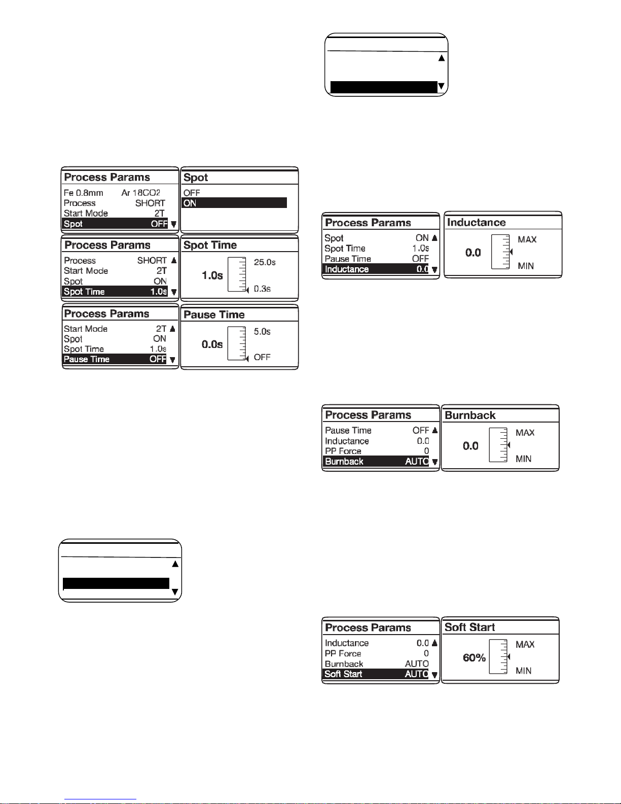
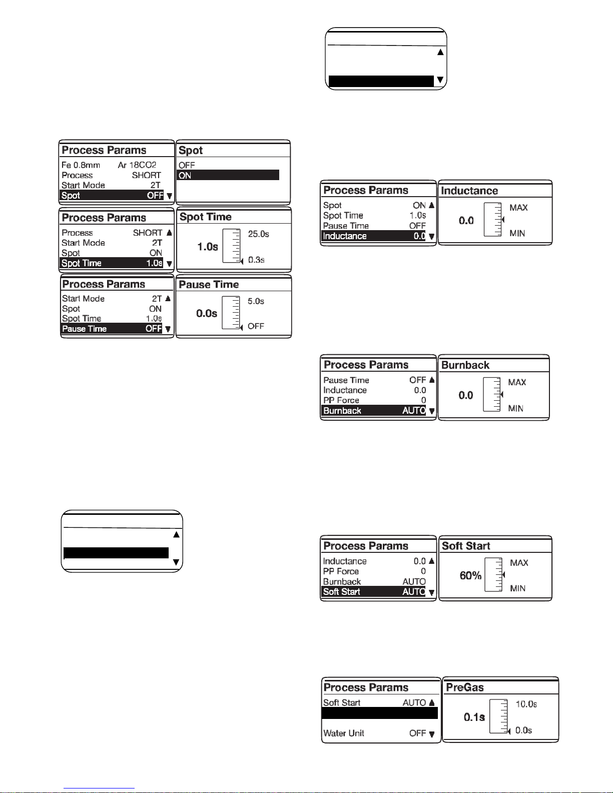
Tempo di puntatura e intermittenza (Spot).
Se selezioniamo il tempo di spot ON, sul display compare
4 COM
ANDI POSTI SUL PANNELLO POSTERIORE (Fig. 2)
5
la funzione Spot Time, selezionandola, possiamo regolare
tramite la barra di regolazione, da 0,3 a 25 secondi.
Oltre a questa funzione sul display compare Pause Time,
selezionandola, possiamo regolare tramite la barra di
regolazione il tempo di pausa tra un punto o un tratto di
saldatura e l’altro, il tempo di pausa varia da 0 (OFF) a 5
secondi.
Per accedere alle funzioni Spot Time e Pause Time bisogna
premere per meno di 2 secondi la manopola A.
La regolazione si fa sempre tramite la manopola A, per
confermare è sufficiente premerla per meno di 2 secondi,
una volta confermata la scelta si ritorna sempre alla
schermata (PROCESS PARAMS).
(HSA) Hot Start Automatico
Il display B visualizza la sigla OFF = Spento.
Se si preme il tasto A il display B visualizza la sigla On = Attivo.
Se si attiva la funzione, compaiono in sequenza le sigle:
- START CURR
Regolazione (10-200%) della velocità del filo corrisp ondente
alla corrente di saldatura impostata con la manopol a A nei
programmi di saldatura.
- S.C. TIME
E' il tempo, espresso in secondi, di durata della corrente di
start precedentemente impostata. Regolazione 0,1 - 10 sec.
- SLOPE TIME
Regolazione 0,1-10 sec. Definisce il tempo di raccordo tra l a
prima corrente (START CURR) e la corrente di saldatura
impostata con la manopola A nei programmi di saldatura.
CRA Crater Current
Il display B visualizza la sigla OFF = Spento. Se si preme il tasto
A il display B visualizza la sigla On = Attivo.
Se si attiva la funzione, compaiono in sequenza le sigle:
- SLOPE TIME
Regolazione 0,1-10 sec. Definisce il tempo di raccordo tra l a
corrente di saldatura e la corrente crater impostata con la
manopola A nei programmi di saldatura.
- CR ATER CUR R
Regolazione (10-200%) della velocità del filo corrisp ondente
alla corrente di saldatura impostata con la manopol a A nei
programmi di saldatura.
- C.C. TIME
E' il tempo, espresso in secondi, di durata della corrente di
crater precedentemente impostata. Regolazione 0,1-10 sec.
Induttanza (Inductance).
La regolazione può variare da -9,9 a +9,9. Lo zero,
regolazione impostata dal costruttore, se il numero è
negativo l’impedenza diminuisce e l’arco diventa più duro
mentre se aumenta diventa più dolce.
Per accedere alla funzione è sufficiente evidenziarla usando
la manopola A e premendola per meno di 2 secondi, sul
display B compare la barr a di rego lazion e, possiamo vari are
il valore e confermare premendo la manopola A per meno di
2 secondi.
Bu
rnback AUTO
La regolazione può variare da -9,9 a +9,9. Serve a regolare
la lunghezza del filo uscente dall’ugello gas dopo la
saldatura. A numero positivo corrisponde una maggiore
bruciatura del filo.
La regolazione del costruttore è in Auto.
Per accedere alla funzione è sufficiente evidenz iarla usando
la manopola A e premendola per meno di 2 secondi sul
display B compare la barra di regolazione, possiamo varia re
il valore e confermare premendo sempre la manopola A per
meno di 2 secondi.
Soft Start
AUTO
La reg olazione p uò variare da 0 a 100%. E’ la v elocità de l
filo, espressa in percentuale della velocità impostata per la
saldatura, prima che lo stesso tocchi il pezzo da saldare.
Questa regolazione è importante per ottenere sempre buone
partenze.
La regolazione del costruttore è in Auto.
Per accedere alla funzione è sufficiente evidenz iarla usando
la manopola A e premendola per meno di 2 secondi sul
display B compare la barra di regolazione, possiamo varia re
il valore e confermare premendo sempre la manopola A per
meno di 2 secondi.
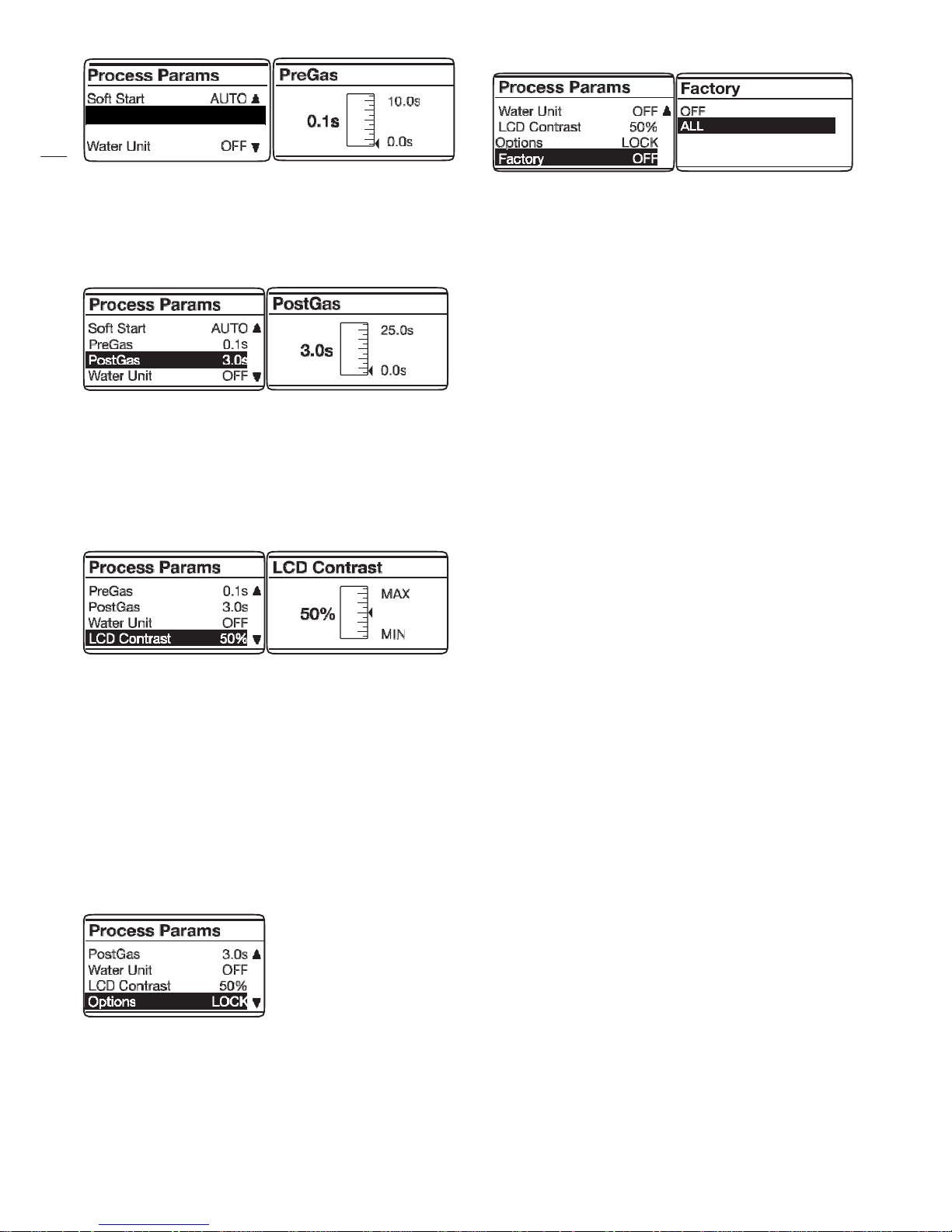
Pre Gas
La reg
olazione può variare da 0 a 10 secondi.
Per accedere alla funzione è sufficiente evidenziarla
usando la manopola A e premendola per meno di 2
secondi sul display B compare la barra di regolazione,
possiamo variare il valore e confermare premendo sempre
HSA ON
CRA OFF
Start Mode 2T
Process SHORT
Process Params
CRA ON
HSA OFF
Process SHORT
Process Params
6
la manopola A per meno di 2 secondi.
Post Gas
La reg
olazione può variare da 0 a 25 secondi.
Per accedere alla funzione è sufficiente evidenziarla
usando la manopola A e premendola per meno di 2
secondi sul display B compare la barra di regolazione,
possiamo variare il valore e confermare premendo sempre
la manopola A per meno di 2 secondi.
LCD Contrast
La reg
olazione può variare da 0 al 100%.
Questa funzione serve per rendere più o meno luminos o il
display B.
Per accedere alla funzione è sufficiente evidenziarla usando
la manopola A e premendola per meno di 2 secondi sul
display B compare la barra di regolazione, possiamo varia re
il valore e confermare premendo sempre la manopo la A per
meno di 2 secondi.
Options LOCK
Per accedere alla funzione e sufficiente evidenziarla usando
la manopola A e premendola per meno di 2 secondi sul
display B compaiono un numero seriale SN e 8 zeri.
Questa funzione serve per sbloccare tutte le curve
sinergiche del processo pulsato.
Per sbloccare le curve bisogna inserire al posto degli zeri un
codice alfa numerico, questo deve essere richiesto al propr io
rivenditore.
Una volta ottenuto il codice è sufficiente inserirlo al posto
degli zeri, ogni lettera o numero che si inserisce d eve essere
confermato premendo brevemente la manopola A, dopo aver
inserito il codice, premendo sulla manopola A per un tempo
maggiore di 2 secondi si ha lo sblocco del processo Pulsato
e sul display B di fianco alla funzione Options verrà scritto
UNLOCK (Sbloccato).
Factory OFF
Lo scopo è quello di riportare la saldatrice alle impostazioni
di prima fornitura.
Per accedere alla funzione è sufficiente evidenziarla usando
la manopola A e premendola per meno di 2 secondi sul
display B compaiono le scritte OFF e ALL. Evidenziando la
scritta ALL e premendo brevemente la manopola A si
esegue il reset e sul display B compare la scritta Factory
Done che dimostra la riuscita del reset. Per ritornare alla
schermata precedente è sufficiente premere per più di 2
secondi la manopola A.
N.B. Su tutte le funzioni che per regolare hanno la barra di
regolazione è possibile riportarsi al valore iniziale (default).
L’operazione può essere eseguita solo quando sul display B
compare la barra di regolazione e si esegue premendo sulla
manopola A per più di 2 secondi.
(Arc Length - Spot Time - Pause Time – Inductance - Burnback
– Soft Start – Pre Gas – post Gas – LCD Contrast).
7 MANUTENZIONE
Periodicamente controllare che la saldatrice e tutti i colle gamenti
sian
o in condizione di garantire la sicurezza dell’operatore.
Dopo aver eseguito una riparazione fare attenzione a riordinare
il cablaggio in modo che vi sia un sicuro isolamento tra le parti
connesse all’alimentazione e le parti connesse al circuito di
saldatura.
Evitare che i fili possano andare a contatto con parti in
movimento o con parti che si riscaldano durante il
funzionamento. Rimontare le fascette come sulla macchina
originale in modo da evitare che, se accidentalmente un
conduttore si rompe o si scollega, possa avvenire un
collegamento tra alimentazione e i circuiti di saldatura.
PreGas 0.1 s
PostGas 3.1 s
7
INSTRUCTION MANUAL FOR WIRE WELDING MACHINE
IMPORTANT
READ THIS MANUAL AND THE SAFETY RULES MANUAL
CAREFULLY BEFORE INSTALLING, USING, OR
SERVICING THE WELDING MACHINE, PAYING SPECIAL
ATTENTION TO SAFETY RULES. CONTACT YOUR
DISTRIBUTOR IF YOU DO NOT FULLY UNDERSTAND
THESE INSTRUCTIONS.
This machine must be used for welding only.
It must not be used to defrost pipes.
It is also essential to pay special attention to the "SAFETY
RULES" Manual. The symbols next to certain paragraphs
indicate points requiring extra attention, practical advice or
simple information.
This MANUAL and the "SAFETY RULES" MANUAL must be
stored carefully in a pica familiar to everyone involved in using
the machine.
They must be consulted whenever doubts arise and be kept
for the entire lifespan of the machine; they will also be used for
ordering replacement parts.
1 GENERAL DESCRIPTION
1.1 SPECIFICATIONS
This manual has been prepared for the purpose of educat ing
personnel assigned to install, operate and service the welding
machine.
This welding machine is a power source developed with
inverter technology, suitable for MIG.
Upon receiving the machine, make sure there are no broken
or damaged parts.
The purchaser should address any complaints for losses or
damage to the vector.
Please indicate the article and serial number whenever
requesting information about the welding machine.
1.2 EXPLANATION OF TECHNICAL SPECIFICATIONS
IEC60974-1 The welding machine is manufactured
IEC609
74-10 according to these international standards.
CL. A Machine for professional and industrial
use.
Single-phase static transformer-rectifier
frequency converter.
MIG-MAG Suitable for MIG-MAG welding.
U
0
Secondary open-circuit voltage.
X Duty cycle percentage. The duty cycle
expresses the percentage of 10 minutes
during which the welding machine may run at
a certain current without overheating.
I
2
Welding current
U
2
Secondary voltage with current I2.
U
1
Rated supply voltage
50 or 60 Hz single-phase power supply.
I
1
max Max. absorbed current at the corresponding
current I
2
and voltage U2.
I1 eff This is the maximum value of the actual
current absorbed, considering the duty cycle.
This value usually corresponds to the capacity
of the fuse (delayed type) to be used as a
protection for the equipment.
IP23 Protection rating for the housing.
Grade 3 as the second digit means that this
equipment is suitable for use outdoors in the
rain.
Suitable for use in high-risk environments.
NOTES: The welding machine has also been designed for use
in environments with a pollution rating of 3. (See IEC 60664).
2 INSTALLATION
•
Only
skilled personnel should install the machine.
•
All connections must be carried out according to
current regulations, and in full observance of safety
laws.
Make sure that the supply voltage corresponds to the value
indicated on the power cable. If it is not already fitted, connect
a plug suited to the power cable, making sure that the
yellow/green conductor is connected to the earth pin.
The capacity of the overload cut-out switch or fuses installed
in series with the power supply must be equivalent to the
absorbed current I1 max. of the machine.
2.1 PLACEMENT
Place the welding machine in a ventilated area.
Dust, dirt, and any other foreign matter entering the welding
machine can interfere with ventilation and thus with smooth
operation.
Therefore, in relation to the environment and working
conditions, it is important to keep the internal parts clean.
Clean using a jet of dry, clean air, being careful to avoid
damaging the machine in any way.
Before working inside the welding machine, make sure it is
unplugged from the power mains.
Any intervention carried out inside the welding machine must
be performed by qualified personnel.
2.2 PROTECTIONS
2.2.1 Block protection
In the event of a malfunction, the display screen B will show
the message WARNING to identify the type of fault.
If this message does not disappear when the machine is
switched off and back on, contact the after-sales service.
2.2.2 Overload cut-out
This appliance is protected by a thermostat that prevents
machine operation whenever acceptable temperatures are
exceeded.
In these conditions, the fan continues to operate and the
display screen B shows the message WARNING tH in flashing
mode.
3 CONTROLS ON THE FRONT PANEL (Pict. 1)
A - KNOB
Selects and adjusts both the welding functions and
parameters.
B - DISPLAY SCREEN.
This displays both the welding parameters and all the
welding functions.
C - CENTRALIZED COUPLING
To which the welding torch must be connected.
D - EARTH LEAD OR SOCKET
Where you must connect the earth cable connector.
8
4 CONTROLS LOCATED ON REAR PANEL (Pict. 2)
E - SWITCH.
Starts and stops the machine
F - MAINS CABLE
G - GAS PIPE CONNECTION.
5 START-UP
Make sure that the supply voltage corresponds to the rated
voltage of the welding machine.
Size the protective fuses based on the data listed on the
technical specifications plate.
Connect the gas hose of the welding machine to the pressure
regulator of the cylinder.
Mount the MIG torch on the fitting C.
Connect the earth cable to the socket D and the earth clamp
to the workpiece. Make sure that the groove of the rollers
matches the wire diameter used.
To replace if necessary: open the side door, mount the wire
coil and slip the wire into the feeder and torch sheath, block
the wire press rollers with the knob and adjust the pressu re.
Turn on the machine.
Select the suitable synergic curve, following the instructions
given in the service functions (PROCESS PARAMS)
paragraph. Remove the gas nozzle and unscrew the current
nozzle of the torch. Press the torch button until the wire comes
out. BE CAREFUL to keep your face away from the end
lance while the wire is coming out, screw up the current
nozzle and fit the gas nozzle.
Open the canister adapter and adjust the gas flow to 8 – 10
l/min.
During welding, the display screen B displays the actual work
current and voltage.
The displayed values may be slightly different to those set.
This can depend on numerous different factors - type of torch,
thickness different to nominal thickness, distance between
current nozzle and the material being welded, and the welding
speed.
After welding, the current and voltage values remain stored on
the display B, where the word HOLD is displayed.
To display the set values, the knob A will have to be moved
slightly, while, by pushing the torch button without welding, the
display screen B shows the empty voltage value and a curr ent
value of 0.
If, while welding the maximum current and voltage values are
exceeded, said values are not stored on the displa y and the
word HOLD is not displayed.
NOTE If 0.6mm diameter wires are used the welding torch
sheath should be replaced with one of suitable internal
diameter.
If the internal diameter of the sheath is too big it does not
guarantee smooth wire feeding.
6 DESCRIPTION OF FUNCTIONS SHOWN ON THE
DISPLAY SCREEN B.
When the machine is switched on, for a few moments the
display screen B displays: the article number of the machine,
the version and development date of the software, and the
release number of the synergic curves.
Immediately after switch-on, the display screen B shows: the
synergic curve used, the welding mode 2T or 4T, SPOT
function, if active, the welding process "SHORT or PULSED
(optional)", the welding current, the speed of the welding wire
in metres/min, the welding voltage and the recommended
thickness.
To increase or decrease the welding parameters, simply
adjust by means of knob A. The values all change together in
a sy
nergic way.
To change the welding voltage V, simply press the knob A for
less than 2 seconds. The display screen will show (Arc
Length) an adjustment bar with central 0. The value can be
changed by means of the knob A from -9.9 to 9.9. To exit from
the function, briefly press the knob A.
6.1
SERVICE FUNCTIONS (PROCESS PARAMS) SHOWN
ON THE DISPLAY SCREEN B.
To access these functions, we must start from the main
display page and press the knob A for at least 2 seconds.
To enter the function, simply select it by means of the knob A
and press it for less than 2 seconds.
To return to the main display page, press the knob A for at
least 2 seconds.
The functions that can be selected are:
Synergic curve (Wire Selection).
To choose the synergic curve, by means of the knob A, it
is necessary to select and press on the curve presented by
the display screen B. Simply select the curve of interest
and confirm the choice by pressing the knob A for less
than 2 seconds.
After pressing the knob A return is made to the previous
display page (PROCESS PARAMS).
Pro
cess
Use knob A to choose or confirm a welding mode by
selecting and pressing Short or Pulsed (optional) for less
than 2 seconds.
Short indicates that the short synergic welding mode is
selected.
Pulsed indicates that the pul sed synergic welding mode is
selected.
Welding mode (Start Mode).
Mode 2T, the
machine starts welding when the torch
button is pressed and stops when this is released. Mode
4T, to start welding, press and release the torch button. To
complete welding, press and release again. To choose the
welding start mode 2T or 4T, select one of the 2 modes by
means of the knob A and press the knob A for less than 2
seconds to confirm the choice. This operation always
returns us to the previous display page (PROCESS
PARAMS).
Spot a
nd pause time (Spot).
If we select the spot ON time, the Spot Time function
appears on the display screen. If we select this, we can
adjust it from 0.3 to 25 seconds by means of the
9
adjustment bar. Besides this function, the display screen
also shows Pause Time. If we select this, by means of the
adjustment bar, we can regulate the pause time between
one welding point or section and another. The pause time
varies between 0 (OFF) and 5 seconds.
To access the Spot Time and Pause Time functions,
press the knob A for less than 2 seconds. Adjustment is
always made by means of the knob A. To confirm, simply
press it for less than 2 seconds. Once the choice has been
confirmed, return is always made to the display page
(PROCESS PARAMS).
HS
A Automatic Hot Start
Display B shows the message OFF = Off. Pressing the knob A
causes the display B to show the message On = Active.
If this function is activated, the following messages to appear
in sequence:
- START CURR
Range 1-20 (10-200%) of the wire speed corresponding to
the welding current set using knob A in the welding
programs.
- S.C. TIME
This is the duration, expressed in seconds, of the
previously set start current. Range 0.1-10 sec.
- SLOPE TIME
Range 0.1-10 sec. Defines the interface time between the
first current (START CURR) and the welding current set
using knob A in the welding programs.
CRA Crater Current
Display B shows the message OFF = Off. Pressing the knob A
causes the display B to show the message On = Active.
If this function is activated, the following messages to appear
in sequence:
- SLOPE TIME
Range 0.1-10 sec. It defines the interface time between
the welding current and the crater current set using knob A
in the welding programs.
- CR ATER CUR R
Range (10-200%) of the wire speed corresponding to the
welding current set using knob A in the welding programs.
- C.C. TIME
This is the duration, expressed in seconds, of the
previously set Crater current. Adjustment range 0.1–10
sec.
Inductance
Adjustment can vary from -9.9 to +9.9. Factory setting is
zero. If the figure is negative, the impedance drops and the
arc becomes harder, while if it increases, the arc is softer.
To access this function, simply highlight it using the knob A
and press it for less than 2 seconds. The display screen B
shows the adjustment bar. The figure can be changed an d
confirme
d by pressing the knob A for less than 2 seconds.
A
UTO burnback
The adjustment can vary from -9.9 to +9.9. Its purpose is
to adjust the length of the wire coming out of the gas
nozzle after welding. A positive figure corresponds to
greater wire burning. Default is Auto.
To access this function, simply highlight it using the knob A
and press it for less than 2 seconds. The display screen B
shows the adjustment bar. The figure can be changed an d
confirmed by pressing the knob A for less than 2 seconds.
Soft Start AUTO
Adjustment can vary from 0 to 100%. This is the wire
speed expressed in percentage of the speed set for
welding, before the wire touches the piece to be welded.
This adjustment is important to obtain always good starts.
Default is Auto.
To access this function, simply highlight it using the knob A
and press it for less than 2 seconds. The display screen B
shows the adjustment bar. The figure can be changed an d
confirmed by pressing the knob A for less than 2 seconds.
Pre Gas
T
he adjustment can vary from 0 to 10 seconds.
To access this function, simply highlight it using the knob A
and press it for less than 2 seconds. The display screen B
shows the adjustment bar. The figure can be changed an d
confirmed by pressing the knob A for less than 2 seconds.
HSA ON
CRA OFF
Start Mode 2T
Process SHORT
Process Params
CRA ON
HSA OFF
Process SHORT
Process Params
PostGas 3.1 s
PreGas 0.1 s

10
Post Gas
The adjustment can vary from 0 to 25 seconds.
To access this function, simply highlight it using the knob A
and press it for less than 2 seconds. The display screen B
shows the adjustment bar. The figure can be changed an d
confirmed by pressing the knob A for less than 2 seconds.
LCD Contrast
The adjustment may range from 0 to 100%.
This function can be used to increase or decrease the
brightness of display screen B.
To access this function, simply highlight it using the knob A
and press it for less than 2 seconds. The display screen B
shows the adjustment bar. The figure can be changed an d
confirmed by pressing the knob A for less than 2 seconds.
Options LOCK
To access this function, simply highlight it using the knob A
and press it for less than 2 seconds. The display screen B
will show a serial number SN and 8 zeros.
The purpose of this function is to unlock all the synergic
curves of the pulsed process.
To unlock the curves, instead of the zeros, an
alphanumeric code must be entered. This must be
requested from your dealer.
Once the code has been obtained, simply enter it in place
of the zeros: each letter or figure entered must be
confirmed by briefly pressing the knob A. After entering the
code, by pressing the knob A for more than 2 seconds, all
the Pulsed process curves are unlocked and the display
screen B shows UNLOCK alongside the Options function.
Factory OFF
The purpose is to return the welding machine to the
original default settings.
To access the function, simply highlight it using the knob
A. By pressing this for less than 2 seconds, the display
screen B shows the words OFF and ALL. By highlighting
the word ALL and briefly pressing the knob A reset is
made and the display screen B shows Factory Done!!
This indicates the reset has been successful. To return to
the previous display page, simply press the knob A for
more than 2 seconds.
NOTE. For all the functions adjusted by means of the
adjustment bar, the initial default value can be reset.
This operation be performed by pressing the knob A for more
than 2 seconds only once the adjustment bar appears on the
displ
ay screen B.
(Arc Length - Spot Time - Pause Time - Inductance, Burnback
– Soft Start - Pre Gas - Post Gas - LCD Contrast).
7 MAINTENANCE
Periodically make sure that the welding machine and all
connections are in good condition to ensure operator safet y.
After making a repair, be careful to arrange the wiring in such
a way that the parts connected to the power supply are safely
insulated from the parts connected to the welding circuit. Do
not allow wires to come into contact with moving parts or
those that heat up during operation. Mount the clips as on the
original machine to avoid, if a conductor accidentally breaks or
disconnects itself, the occurrence of a connection between
power supply and the welding circuits.
 Loading...