

5041D2E18
1
Eletta
Flow Monitor
Installation
and
Operations
Manual
Models
S2, S25, S02 and
S05
5041D2E18
2
Please note that this manual is available as a PDF-file
on our website www
.eletta.com along with other information such as
technical leaflets and application reports.
This gives you the option either to print out the desired
publications or watch it on the screen. Of course this also
enables you to benefit from the use of modern software.
For instance you can adjust the size of the image
to suit your specific need.
Notice of Proprietary Rights
This manual contains confidential technical data, including trade secrets and proprietary
information, which is the property of Eletta Flow AB, Sweden.
These data are disclosed to you under the permission that you use it with limits within your
company only, not including manufacture or processing uses.
Any other use is strictly prohibited without prior written permission from Eletta Flow AB,
Sweden.

5041D2E18
3
Customer Service
Our Customer Service Center is available to answer any of your commercial
or technical questions at our normal office hours, 8.00 to 16.30 C.E.T. (8 a.m.
to 4:30 p.m. Central European Time) The switchboard is manned 7.00 to
19.00 (7 a.m. to 7 p.m. C.E.T.) Before and after normal office hours on
Monday to Friday, you can leave a message to the person at the switchboard
and our Customer Service staff will contact you later. Questions and inquiries
will be dealt with immediately over the phone or through fax and e-mail. The
above hours are not valid at National Holidays and annual plant close down,
such as Christmas and summer holidays.
Eletta has an International Network of Authorized Distributors, who are able
to give you both technical and commercial assistance with our Products.
Please refer to Section 7 for your nearest Distributor or contact Eletta Flow in
Sweden, if no representative is to be found in your area/country.
As we have tried to write this manual as carefully and comprehensive as pos-
sible from the beginning, we understand that you can still run into problems,
which are not clearly described in this manual. In the unlikely event of such an
incident, we kindly ask you to make sure that you go trough the manual care-
fully, before contacting our Distributors or Eletta AB in Sweden. This is to
save valuable time for any of us involved in the Eletta Products, as it is some-
times easy to overlook a specific sentence in the manual. If you after doing
this still are not able to solve the problem, our Customer Service staff, at the
below numbers and addresses, are more than happy to help you.
You will also find useful information about our Products and organization on
our homepage, which you can find at the address below.
This is how you can reach us:
Via Phone: +46 8 603 07 80 (Orders & Inquiries)
+46 8 603 07 70 (Switchboard)
Distributors: See www.eletta.com
Via Mail:
Via e-mail:
Website:
Eletta Flow AB
P.O.Box 5084
SE-141 05 Kungens Kurva, SWEDEN
info@eletta.com
www.eletta.com
Our Customer Service Center is available to answer any of your commercial or
technical questions at our normal ofce hours, 8.00 to 16.30 C.E.T. (8 a.m.to
4:30 p.m. Central European Time) The switchboard is manned 7.00 to 19.00 (7
a.m. to 7 p.m. C.E.T.) Before and after normal ofce hours on Monday to Friday, you can leave a message to the person at the switchboard and our Customer
Service staff will contact you later. Questions and inquiries will be dealt with
immediately over the phone or through fax and e-mail. The above hours are not
valid at National Holidays or other occations when production is closed.
Eletta has an International Network of Authorized Distributors, who are able
to give you both technical and commercial assistance with our Products. Visit
www.eletta.com for contact details.
Even though we have tried to write this manual as carefully and comprehensive as possible from the beginning, we understand that you can still run into
problems, which are not clearly described in this manual. In the unlikely event
of such an incident, we kindly ask you to make sure that you go through the
manual carefully, before contacting our Distributors or Eletta AB in Sweden.
This to save valuable time for any of us involved in the Eletta Products, as it is
sometimes easy to overlook a specic sentence in the manual. If you after doing
this still are not able to solve the problem, our Customer Service staff, at the below numbers and addresses, are more than happy to help you. You will also nd
useful information about our Products and organization on our homepage, which
you can nd at the address below.

5041D2E18
4
General Information .......................................................................... 5
1.1 Description ............................................................................... 5
1.2 Specifications .......................................................................... 6
Installation ........................................................................................ 10
2.1 Unpacking .............................................................................. 10
2.2 Procedures before Installation ............................................... 10
2.3 Installation of the Pipe Section ............................................. 11
2.4 Separate mounting of the Pipe Section and Control Unit ..... 12
2.5 Installation and changing the Control Unit ............................ 14
2.6 Pressure Drop ........................................................................ 16
2.7 Electrical Installation .............................................................. 18
Operation ......................................................................................... 19
3.1 Principle of operation, DP-Flow Measurement ...................... 19
3.2 Change of Flow Range ......................................................... 19
3.3 Adjustment of switch point, S2 and S25 ............................... 21
3.4 Change of Flow Direction ...................................................... 22
3.4.1 Flow Direction Selector (from January 2013) ......................... 22
3.4.2 Flow Direction Selector (until December 2012) ..................... 23
3.5 Change of Dial Orientation ..................................................... 24
Trouble shooting .............................................................................. 25
4.1 Verification of Flow ................................................................. 25
4.2 Electrical connections ............................................................ 26
4.3 Spares .................................................................................... 27
Distributors ...................................................................................... 28
Tables ............................................................................................... 29
6.1 Measuring Ranges ................................................................. 29
6.2 Weight and Dimensions ......................................................... 30
Spare Parts ...................................................................................... 31
7.1 Exploded Drawing S-GL/FA ................................................... 32
7.2 Exploded Drawing S-GSS/FSS ............................................. 34
Contents
1
2
3
4
5
7
6

5041D2E18
5
General Information
Description
The Eletta Flow Monitor is used to control and measure flow of liquids and
gases in pipes from size 15 mm to 500 mm (larger pipes as an option). They
have been manufactured for over 65 years and are well known for its reliability. They are used where operational safety demands, efficient supervision and
rugged installation is needed, all over the world. Eletta Flow AB in Sweden is
certified according to ISO9001 and ISO14001.
The Eletta Flow Monitor is based on the proven and dependable differential
pressure principle, using interchangeable orifice plates for different measuring ranges. The Flow Monitors are working with two different differential
pressure ranges, i.e. 50 – 200 mbar for the S2/S02 and 22 – 550 mbar for the
S25/S05, depending on the desired and ordered flow range. The same goes for
our models; V1 and V15, D2 and D5 and R2 and R5. Due to the working principle of the instrument, it is of outmost importance that the installation instructions (chapter 2) are followed carefully in order to get the proper function of
the instrument.
The Eletta Flow Monitor models S2/S02 and S25/S05 will give you an accuracy of +/–5% F.S. (Full Scale) if installed in the right way. (See chapter 1.2
“Specifications”, for complete information)
The Instrument consists of two parts mainly i.e. the Pipe Section and the
Control Unit. The Pipe Section is the part that is to be mounted in the process
pipe and the Control Unit is mounted directly (standard) or remote on/to the
Pipe Section. The Control Unit is giving you the Flow information and also
contains all electrical connections for input and output.
The Pipe Sections are available in different process connections with the following standards;
Threaded connections in BSP or NPT from 15 mm (
1
/2”) to 40 mm (1 1/2”)
depending on the chosen material of construction.
Flanged (wafer) connection from DN15 /PN16 (ANSI 1/2”/150 lbs) to DN
500/PN16 (ANSI 20”/150lbs ) depending on the chosen material of construction. The DIN-standard flanged units are colored blue, the ANSI-standard
units are colored green (>50 mm < 100 mm) for easy recognition in the field.
The Control Units S02 and S05 have a local readout and S2 and S25 are also
1
1.1
1

5041D2E18
6
equipped with two independent adjustable alarms (micro switches) which can
be set for low and high flow alarm. The readout has a scale, which shows you
the ordered flow range with a multiplier as a standard. The standard scales
have the following designations; for S2/S02 the scale goes from the number 4
to 8 (1:2 turndown). This is the value that you have to multiply the small multiplier (sticker) figure at the bottom of the scale with, in order to read the actual flow in the values you have ordered i.e. liters/min, m3/hours, USGPM.
etc. (also shown at the bottom of the scale) For the S25/S05, the scale goes
from 1 to 5 and hence, this is the value you use together with the multiplier at
the bottom of the scale, to read the actual Flow through the Monitor.
The Control Unit can also be fitted with a special ordered scale (direct reading
scales) as an option, for example; l/min, m3/h, USG/min etc. for easy reading
and then you have no multiplier at the bottom of the scale.
Specifications
The only flow difference between the S2/S02 and S25/S05 is the turn down of
the flow range i.e. the S2/S02 has a 1:2 turn down (for example; 50 –100
l/min) and the S25/S05 has a turn down of 1:5 (for example; 20 – 100 l/min).
Accuracy: <+/–5% F.S (full scale) within 20-80 % of the chosen Flow range
<+/–10% F.S.(full scale) within 100% of the chosen Flow range
The accuracy stated is achievable if the installation instruction
is followed given in this manual. It is recommended that you
always choose the Flow Range of the Flow Monitor so that the
normal flow is in the middle of the Monitor Flow Range.
Make sure that the expected alarm set points are within the
chosen flow range. For example: If you have a flow of 110
l/min maximum and the normal Flow is at 90 l/min, chose the
Eletta Flow Monitor S2 with a Flow Range of 60–120 l/min.
This will give you the highest accuracy since your flow is in
the middle of the Monitor Flow Range and give you a lower
pressure loss.
Repeatability: < 2 %
Pressure: Max:16 bar, (232 PSI), higher test pressure as an option.
Min: A line pressure of apx.: 0,7 – 1,0 bar (10 – 14,5 PSI) is
required for proper operation.
Temperature: Control Unit
–20°C to 90°C (–4°F to 200°F), standard
1
1.2
1

5041D2E18
7
–20°C to 120°C ( –4°F to 250°F), optional
The lower temperature is not valid for Monitors equipped with
FPM soft parts. FPM is limited to –5 °C (23 °F).
Higher process temperature with remote installation of
Control Unit (separate mounting, see section 2.4)
These temperature limits are valid for models S2 and S25
(with micro switches)
Temperature limit for S02 and S05 is –20°C to 120°C (–4°F to
250°F). Pls note the FPM soft part remark above, which is
valid also for S02/S05 models.
Pipe Section: The pipe sections are equipped with spacers (holding the orifi-
ce plate) made of Polyamide plastic (PA) material and they can
handle liquid/gas temperature up to 150 °C (300°F).
For higher process temperature, we recommend to use the stainless steel pipe section, which has no spacers.
Dial: 120 mm diameter with mechanical pointer and a linear scale.
Front glass: Acrylic
Process
connection: DN15 – 40 (
1
/2” – 11/2”) for GL-models
DN15 – 25 (
1
/2” – 1”) for GSS -models
DN15 – 400 (
1
/2” – 16”) for FA-models
DN15 – 500 (
1
/2” – 20”) for FSS-models
Alarm/
Contacts: S2 and S25 have 2 (two) micro switch SPDT contacts, inde-
pendently adjustable within the ordered Flow range.
S02 and S05 has no micro switch contacts included; only a
dial for local indication of Flow.
Micro
switch spec: Contact surfaces are silver plated as standard.
Hystereses: +/–10%
Voltage: max. 460 VAC
Current: max.15 A
Inductive load: 15A @ 380 VAC
0,03A @ 230 VAC
5A @ 30 VDC
Type: SPDT
1
1
Contact surfaces are silver plated as standard.
Hystereses: 10%
Rated voltage: 480 VAC/15A
Breaking current: 15@125, 250, 480 VAC
Resistive load: 2A@30 VDC
0,4A@125 VDC
0,2A@230 VDC
Type: SPDT

5041D2E18
8
For intrinsically safe (IS) applications, we recommend to order
micro switches with gold plated contact surface, which are
better suited for the voltage and current limitations in the Exregulations.
Protection
Class: As an option, hermetically sealed micro switches are available (1HM1)
Control Unit: IP43 (NEMA 3R), standard
IP65 (NEMA 4x), optional
Aluminum alloy, alodine and epoxy polyester coated. 3 cable
glands included (PG16/PR22,5)
Material; Pipe Section
and Diaphragm
Housing: Type GL; SM 2862 (B.S CZ132) de-zincificated – copper
1
1
Material; Diaphragm housing and pipe section:
Type GL: De-zincicated brass, CW602N, EN12420
Type GSS: Seaworthy stainless steel 1.4470
Type FA: Housing: De-zincicated brass, CW602N, EN12420
Pip
e section: <DN40 (ANSI 1 1/2”) Bronze CC491K / EN1982
>
DN40 (ANSI 1 1/2”) Painted cast iron, GG25 / DIN1691
Type FSS: Housing: Seaworthy stainless steel 1.4470
Pipe section: Stainless steel 1.4435
For intrinsically safe (IS) applications, we recommend to order
micro switches with gold plated contact surface, which are
better suited for the voltage and current limitations in the Ex-
regulations.
Protection
Class: As an option, hermetically sealed micro switches are available (1HM1)
Control Unit: IP43 (NEMA 3R), standard
IP65 (NEMA 4x), optional
Aluminum alloy, alodine and epoxy polyester coated. 3 cable
glands included (PG16/PR22,5)
Material; Pipe Section
and Diaphragm
Housing: Type GL; SM 2862 (B.S CZ132) de-zincificated – copper
alloy.
Option: Nickel-plating by means of the Canigen process
(90% Nickel and 10% Phosphorus and the thick-
ness is 25 micron)
Type GSS; seaworthy stainless steel SS 2564 (SS 316),
Type FA; <DN50 (ANSI 2”); copper alloy
>DN50 (ANSI 2”); cast iron, epoxy polyester
coated.
Type FSS; stainless steel SS2343 (SS316)
Material
diaphragm: Textile reinforced Hydrated Nitrile rubber (HNBR), standard
on all models except stainless steel.
Textile reinforced EPDM rubber, optional for all models
Textile reinforced Fluorinated rubber, FPM, standard in stainless steel models, optional for others.
Material, O-rings
and other
soft parts: Follows the Diaphragm materials.
Spacer: The spacer holds the orifice plate inside the pipes section and
they are made of Polyamide plastic (PA) as a standard. Max.liquid/gas temperature is 150°C (300°F).
1

5041D2E18
9
contacts (micro switches), which are considered “passive
components” (simple apparatus) and are therefore possible to
use in an intrinsically safe circuit where you feed the micro
switch contacts through an approved pulse isolator (not in-
cluded).
Explosion
Proof: The Flow Monitor itself is not approved as a complete instru-
ment according to EU Hazardous Area EX-regulations.
CEapprovals: The Eletta Flow Monitors conforms with the EU directive for
low voltage no: 72/23/EEC ( EN 60 204-1, Part 1.) We refer to
the certificates issued, which will be sent to you upon request.
They are also available at www.eletta.com.
PEDDirective: Complies with applicable parts in Pressure Equipment
Directive 97/23/EC Module A1. Eletta approved by notified
body Det Norske Veritas with approval number: 0409.
The certificates issued, which will be sent to you upon request
or they can also be found to download on www.eletta.com.
1
contacts (micro switches), which are considered “passive
components” (simple apparatus) and are therefore possible to
use in an intrinsically safe circuit where you feed the micro
switch contacts through an approved pulse isolator (not in-
cluded).
Explosion
Proof: The Flow Monitor itself is not approved as a complete instru-
ment according to EU Hazardous Area EX-regulations.
CE-
approvals: The Eletta Flow Monitors conforms with the EU directive for
low voltage no: 72/23/EEC ( EN 60 204-1, Part 1.) We refer to
the certificates issued, which will be sent to you upon request.
They are also available at www.eletta.com.
PED-
Directive: Complies with applicable parts in Pressure Equipment
Directive 97/23/EC Module A1. Eletta approved by notified
body Det Norske Veritas with approval number: 0409.
The certificates issued, which will be sent to you upon request
or they can also be found to download on www.eletta.com.
Approvals: The micro switches, cables and terminal blocks are approved
according to CSA.
1
Complies with applicable parts in Pressure Equipment Directive
97/23/EC. Conformity assessment has been performed according to module A. Internal production control combined with
module A1. Internal manufacturing checks with monitoring
of the nal assessment, for category 2. Performed by Inspecta
AB, Notied body No. 0409. PED Declaration of conformity
will be sent to you upon request and are also available on
www.eletta.com.
1

5041D2E18
10
Installation
Unpacking
We appreciate that you have decided to purchase our Products and we would
like to ask you to begin the installation by checking your delivery against the
Packing List. Please make sure to check the box for external damages before
opening. If you find external damages, which have also led to damages to the
Flow Monitor inside, you should contact the forwarder/shipper to claim replacement (or the cost of replacement). Check the Monitors’ identification tag
against your purchase order to make sure you have got the right parts with
the right specifications.
All Monitors are individually packed in plastic bags and put into the box either two by two or individually in each box. The plastic bag is to prevent foreign
particles to get inside the Pipe Section, which could prevent proper function of
the Flow Monitor after the installation.
The box is made from recycled environmental friendly material and we kindly
ask you to deal with the waste material in a way that will have as little impact
on the environment as possible.
Procedures before Installation
Note!!! Before any installation or maintenance work, disconnect all
electrical power!
Please check that you are going to mount the Monitor at the lowest point in the
piping system if you are measuring liquids and at the highest point if you are
measuring gases. Also check if the planned flow direction in the system matches the one indicated on the Monitor. There is a red flow direction arrow on
the outside of the pipe section (not the Stainless Steelmodels which have a
marking engraved on the side). If you find this to mismatch, we refer to section 3.4 ”Change of Flow Direction”, to adjust the internal flow director in order to match the desired flow direction. Change of the flow direction on the
Stainless Steel Pipe Sections (FSS/GSS) is not possible in the field without
ordering a new Pipe Section and we kindly ask you to contact your local representative or Eletta Flow AB, Sweden for help.
Check that the pipe section has the right threads or the right flange standard to
match your piping or counter flange.
If you are using the separate/remote execution i.e. Pipe Section and Control
Unit installed in different locations, please check the plastic hoses for any da-
2
2.1
2.2
2
5041D2E18
11
mages or holes that can prevent proper function. The plastic hoses should not
be used in temperatures over 90ºC (194 ºF). If your application temperature
exceeds this temperature/pressure, we recommend to use copper or stainless
steel tubing, depending on the compatibility to the measured gas or liquid (see
section 2.4)
Installation of the Pipe Section
Note!!! Before starting to install the Pipe Section, please make sure
that the piping is not under pressure from flow of liquid/gas!
The pipe section can be installed in any desired direction, vertically or horizontally or angular and the direction arrow on the pipe section denote the direction of the flow. It is very important that the pipe section is mounted with
the correct direction, as the function of the Flow Monitor otherwise will be
prevented. The piping shall be rigid and free from vibrations and hoses connected directly into the Monitors should be avoided as much as possible. If
you have weak piping we advise you to use the M6 mounting holes (only on
GL - series) on the backside of the pipe section, to fasten the pipe section to a
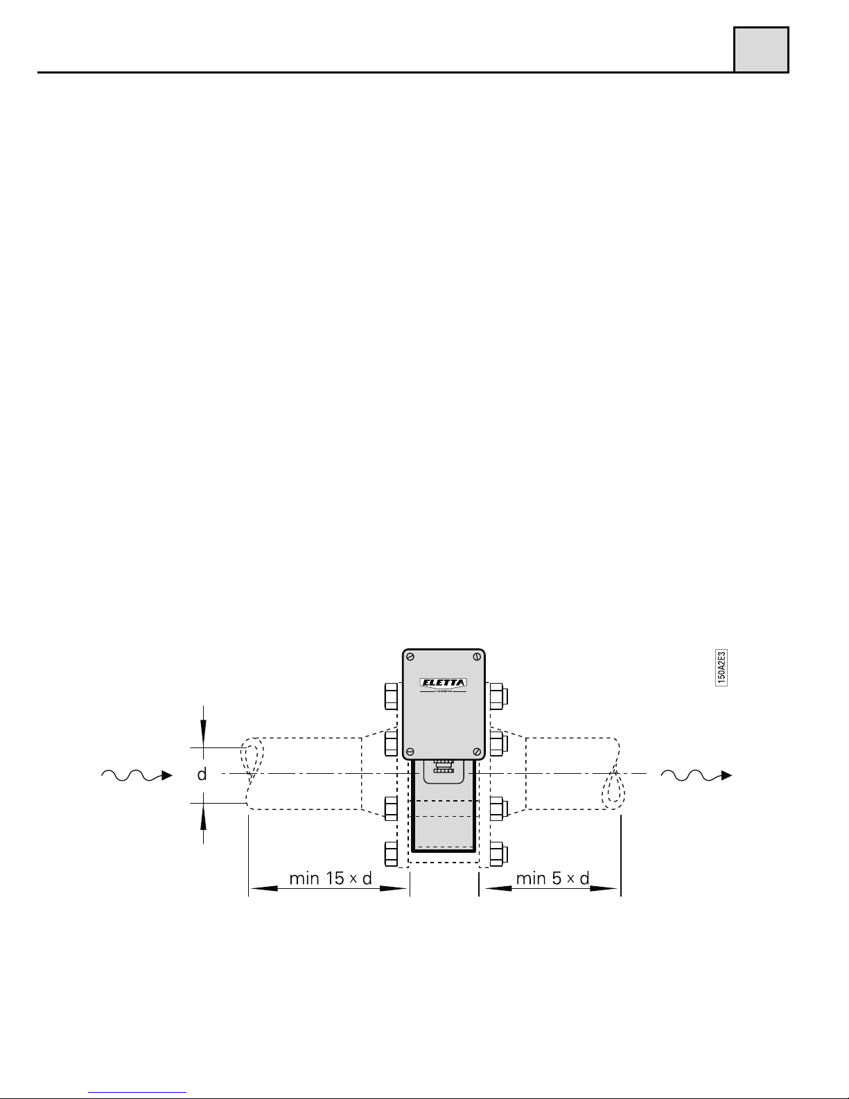
wall or a rigid bracket. The straight runs before and after the Monitor should
not be too short, in order to avoid disturbances, which can cause the Monitor
to show incorrect values. We recommend giving at least 10 - 15 diameters upstream and 5 diameters downstream. (Please see Fig. 1)
The reasons for this procedure is to achieve a stable flow profile inside the
pipe and by doing so, get a true reading. Please be aware of the fact that it is
practically impossible to predict when the flow is stable after disturbances in
the piping, so this must serve as a guideline only. The straight runs must be
2
2.3
Recommended installation of Pipe Section
Figure 1
2

5041D2E18
12
free from valves, bends or in/decreasing diameters. Any of these disturbances
must be placed before and preferably after you start counting the straight
runs.
If you are installing the threaded versions, GL and GSS-versions, please
make sure that you are not using so called ”tube fittings”. We have often
seen them to have a much smaller inside diameter than the pipe section,
even though the size of the thread match. This can create a jet stream of the
fluid/gas, which will cause the differential pressure to be too low and you
will not get a good or accurate reading.
The following inside diameters apply for the threaded Pipe Sections:
GL-and GSS 15 = 16 mm
GL-and GSS 20 = 21 mm
GL-and GSS 25 = 26 mm
GL-40 = 41 mm
Make sure that the Control unit, if mounted directly on the Pipe Section, is
placed on top of the Pipe Section and not under to prevent particles in the fluid to collect in the diaphragm housing. Please use a filter in the pipeline if you
suspect the fluid to contain particles.
The flanged models, FA and FSS-versions, must be aligned with the counter
flange and not placed in stress by tightening the bolts uneven. The flanged
models come with a gasket and we recommend using this, as it is dimensioned
to suit the installation. Please see to that the gasket is properly aligned and not
disturbing the flow. It is also of outmost importance that the connecting pipe
and flange is of the same diameter (inside) and standard as the pipe section. A
mismatch can cause an erratic or incorrect reading of the flow. If needed, please support the Flow Monitors with rigid brackets. There is no problem in attaching the brackets directly to the Flow Monitor (see above), but we recommend mounting them in the pipeline downstream and upstream to avoid unnecessary stress in the installation area.
Separate mounting of the Pipe Section and
the Control Unit
Sometimes separate mounting of the Pipe Section and the Control Unit is requested due to vibrations, high temperature or lack of space. As the Eletta
Flow Monitor is using the differential pressure caused by the orifice plate
mounted in the pipeline and directs these two pressures via two individual
2
2.4
2

5041D2E18
13
2
ports up to the Control Unit, it is also possible to separate the Monitor (Fig.
2) from the Pipe Section -GL/FA into two parts. The pressure is then lead
through either plastic hoses or metallic tubing depending on the liquid,
pressure and temperature.
As a standard, we supply 2x1,75 meter (5.74 feet) of PA plastic, Ø 6 mm (0,23
inch) hoses capable of handling 90ºC (194°F) and 16 bar (232 PSI), together
with two specially made adapters to be mounted on the Pipe Section and
Control Unit respectively. If your application requires metallic tubing (copper
or stainless steel) it has to be provided locally. If you are measuring a chemical liquid or gas, check with the supplier which material you should use in
your tubing. Please make sure to use only 6 mm tubing in order to suit the tube
fittings included in the delivery. There is no actual limitation in the length of
the hoses or tubing, but we recommend placing the units as close as possible
to each other, as this will help in troubleshooting and on-site calibration.
Note!!! The hoses/tubings must have the same length to avoid uneven pressure. If you mount valves (not included in delivery) in the pressure hoses/tubing, it will help you to easily shut them off and remove/exchange the
Control Unit at full process pressure.
The Mounting of three-way/five-way standard valve (not included in delivery)
will allow you to discharge any entrapped air/gas or condense and also provide the possibility to even out the pressure between the plus and minus leg for
zero verification. Please follow the above ”Installation of the Pipe Section” after you have mounted the adapter on to the Pipe Section. As you will use hoses/tubing to lead the pressure up to the Control Unit, it is possible to mount
the Pipe Section in any direction, vertically or horizontally and with the pressure ports pointing up, down or to the side (pls. see section 2.3).
Separate mounting of Pipe Section and Control Unit GL/FA
Figure 2
2

5041D2E18
14
2
Find a suitable place for the Control Unit to be mounted. Use the supplied
bracket to attach it to a wall, pipe or another steady and rigid support. To take
advantage of the large and clear dial, the Control Unit should be clearly visible from a distance and easy accessible for maintenance if needed. Please plan
this with respect to later mounted piping or other obstacles. Install the
hoses/tubing, commencing with the Pipe Section. Check that you have enough
length to cover the distance between the Pipe Section and Control Unit. The
Pipe Section adapter has a (+) and (–) marking engraved and the adapter on
the Control unit too. Please make sure to match (+) to (+) and (–) to (–) on the
adapters. Press the hose/tube end into the coupling and tighten with care.
Proceed to the Control Unit and repeat the above. When you fill up the system
for the first time with liquid, please make sure that all entrapped air in the piping between the Pipe Section and Control Unit is removed. The air can other
wise, as it is a compressible media, cause faulty flow readings.
Installation and changing of the Control Unit
As all Eletta Flow Monitors are designed in sections to achieve a modular and
versatile Flow Monitor, there is a possibility to upgrade/rebuild them and adding other features to your already installed Monitor, by changing the Control
Unit or Pipe Section. If you, for example, would like to upgrade a V- or S-series with mechanical micro switches to a D-series including analog and/or
frequency output, local front display and two independent adjustable relays or
the other way around, this is easily done. You simply order a Control Unit with
Purge valve
Pipe
fitting
Adapter for Control unit
Adapter for pipe section
Hose/
Tubing
Figure 3
2.5
Separate mounting of Pipe Section and Control Unit GSS/FSS
2
the ow range you need, to get the right dial with the right multiplier or direct

5041D2E18
15
range you need, to get the right dial with the right multiplier or direct reading
scale. When you order, you will get the Control Unit with the diaphragm hou-
sing included. Make sure you order the right material in the diaphragm hou-
sing and the soft rubber parts (diaphragm, o-rings and diaphragm lever) and
you will get the Control Unit already tested and calibrated and ready to fit
onto the Pipe Section, without any on-site adjustments or calibration. All
Eletta DP Flow Monitors are working with the same differential pressure wit-
hin their specific range (Pls. see section 1.1).
If you have a Pipe Section designated; -GL or GSS (-FSS), start with ma-
king sure that there is no pressure in the system, as these Pipe Sections do
not have any internal shut-off valves for isolating them from process pressure.
Turn the electric power supply off and then disconnect the cables from the
micro switch electric terminal. If you have a Pipe Section designated; -FA you
will find the included shut-off valves under the brass elbow, which connects
the Control Unit to the Pipe Section.
Turn them counter-wise until you feel the end position and this shuts off the
pressure up to the Control Unit and you can easily remove this. If you have a
Pipe Section designated; -FSS, there is an option to buy this with a shut-off
manifold, but it will not come as a standard.
On the -GL Pipe Section; loosen the four (4) hexagon screws that hold the
diaphragm housing (do not remove the blue housing at any time) to the Pipe
Section. Replace the flow direction selector (3.4.1 and 3.4.2) if damaged, or
if other material is required. Install the new Control Unit and tighten the four
(4) hexagon screws firmly again.
On the -GSS Pipe Section; loosen the two (2) hexagon screws that hold the
diaphragm housing and replace the O-rings to the right material, if necessary.
Install the new Control Unit and tighten the two (2) screws firmly again.
2
2
As an option we have a manifold with shut-off valves, this enables you to
dismount the control unit from the pipe-section during full operation.
Start with making sure that there is no pressure in the system. Turn the
electric power supply off and then disconnect the cables from the micro switch
electric terminal.
reading scale. When you order, you will get the Control Unit with the diaphragm
housing included. Make sure you order the right material in the diaphragm housing and the soft rubber parts (diaphragm, o-rings and diaphragm lever) and you
will get the Control Unit already tested and calibrated and ready to fit onto the
Pipe Section, without any on-site adjustments or calibration. All Eletta DP Flow
Monitors are working with the same differential pressure within their specific
range (Pls. see section 1.1).
On the -FA Pipe Section: untighten the four (4) screws which hold the
diaphragm housing.Replace the ow direction selector (3.4.1 and 3.4.2) if
damaged, or if other material is required to the pipe section. Install the new
Control Unit and tighten the four (4) screws rmly again.
On the -FSS Pipe Section; Loosen the two screws that hold the diaphragm
housing and replace the O-rings to the right material, if necessary. Install the
new Control Unit and tighten the two (2) screws rmly again.
Connect the electrical cables according to your new Control Unit’s possibilities
and for detailed information regarding wiring, please see section 2.7”Electrical
installation”.

5041D2E18
16
Install the new Control Unit and tighten the two (2) screws firmly again. If a
shut-off manifold is installed; do not forget to open up the two (2) shutoff val-
ves again, in order to get a proper function of the Flow Monitor.
Connect the electrical cables according to your new Control Unit’s possibili-
ties and for detailed information regarding wiring, please see section 2.7
”Electrical installation”.
Pressure Drop
The Eletta Flow Monitor is a differential pressure measuring device and therefore it creates a certain pressure drop when in function. There are two different
types of Pressure Drop’s involved, actual pressure drop and permanent
pressure drop. Below we will explain the difference between these two:
When the orifice plate mounted in the Eletta Flow Monitor reduces the flow
area inside the pipe system, a pressure drop over the orifice is created. This is
what we call actual pressure drop. Please refer to chapter 1.1 ”Description”
for actual pressure drop (differential pressure span).
The calculation of the flow is using this pressure drop to calculate the actual
flow value (see calculation below). The actual pressure drop is a temporary
pressure state and the Eletta Flow Monitors are working within this differential pressure created within the Flow range of the Monitor. When the flow has
passed the Monitor, the pressure is then trying to get back to its original pressure and normally after 10 - 15 times the inner diameter of the pipe, the flow
becomes linear and fully developed. This is a normalized flow but due to friction losses over our Flow Monitor, the pressure will not be able to reclaim all
the energy (pressure). This is what we call permanent pressure drop.
The permanent pressure drop can be calculated approximately by ∆ρ
(ppd) =
∆ρ(apd) • (1-β
2
), where the symbols represent:
∆ρ
(ppd) = permanent pressure drop
∆ρ
(apd) = actual pressure drop (see formula below ”actual pressure
drop graph” for calculation)
β = d/D ratio (ratio between bore and inner diameter of the pipe).
This means that for the normal β range (0.2 - 0.7) a typical permanent pres-
sure drop ranges from 0.96 ∆ρ and 0.51 ∆ρ can be expected.
Example:
For the Eletta Flow Monitor S2-GL15 with a flow range of 10 - 20 l/min, the
following example can be used for how to calculate the ∆ρ
(ppd) permanent
pressure drop) at 15 l/min for the said Monitor:
2
2.6
2

5041D2E18
17
d = 10,2 mm
D = 16,0 mm
This gives β = 10,2/16,00
⇒ β = 0,6375 and (1-β
2
) = 0.594
Furthermore, in order to use this β−value in the above formula, we need to determine the ∆ρ
(apd). We can either use the ”Actual Pressure Drop Graph” (fig.
4)
for an approximate value or for intermediate values we can use the formula
below the graph (fig. 4). If we use the formula for calculate the ∆ρ
(apd) at 15
l/min we will get;
∆ρ
(apd) = (15/20) • 200 mbar ⇒ 112,5 mbar
In order to finally get the permanent pressure drop, we use the above described formula: ∆ρ
(ppd) = ∆ρ(apd) • (1-β
2
)and put in the values we have:
∆ρ
(ppd) = 112,5 • 0,594 mbar ⇒ 66,82 mbar
∆ρ
(apd) = (Q/Qmax)
2
* 2000 mmH2O (196 mbar) for turn down ratio of 1:2
or
∆ρ
(apd) = (Q/Qmax)
2
* 5500 mmH2O (539 mbar) for turn down ratio of 1:5
Q = actual flow
Q
max = maximum flow of the Flow Monitor (according to the
installed orifice plate)
The Pressure loss curves in the graph (fig. 4) must serve as a guideline.
2
Actual Pressure Drop Graph
Figure 4
2
2
5041D2E18
18
Electrical Installation
Note!!! An authorized professional person should make all electrical
installations.
This section is not valid for the models S02 and S05 as these are Monitors wit-
hout any micro switches installed and work without the need of electrical power. Before you connect any cables, please make sure that you have the right
power supply within the specifications (see section 1.2 “Specifications”).
All terminal block connections are to be made through the included cable
gland PR22,5/PG16 (and please note that you can have two alternative mountings of the cable gland depending on what side you want to enter with the cables). If you install the Flow Monitor in an Ex-hazardous area, please make
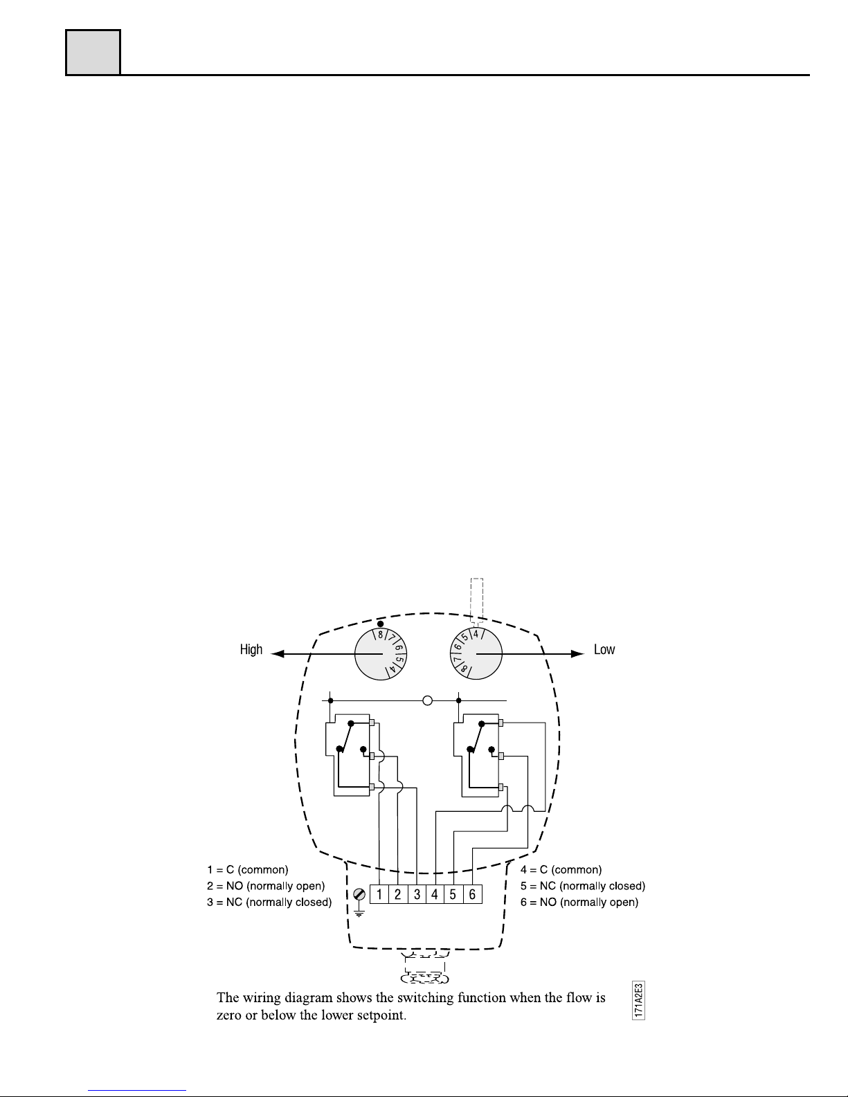
sure to follow local installation procedures and regulations. The terminal
block connections are described in fig.5 below. A grounding screw is to be
found at the side of the terminal block.
Before any circuit is connected/disconnected, make sure that all power is
off!
2
2.7
Figure 5
Setting of high/low flow alarm for the S2/S25
(tool normally placed under top lid)
2

5041D2E18
19
Operation
Principle of operation, DP-Flow Measurement
The Eletta Flow Monitor’s function is based on the proven and dependable diferential pressure principal, using interchangeable sharp-edge orifice plates
for different measuring ranges. This is perhaps the oldest and most widely
used principle for flow metering, mainly because of its simplicity, its relatively low cost and high volume of research data available for predicting the Flow
Monitors behavior. In the Pipe Section, a fixed area flow restriction (the orifice plate) causes a pressure drop, which varies with the flow rate. This pressure drop has a high and a low pressure, which is lead through two channels
from each side of the orifice plate, to the Control Unit. By measure the pressure drop allows flow rate measurement by means of a mathematical formula.
A short form of the calculation can be described as Q=√ ∆ρ.
In most Eletta Flow Monitors, the differential pressure is sensed and measured
mechanically via a rubber diaphragm and linked to an outside of the process
liquid/gas, mechanism. This mechanism transforms the movement into a Flow
rate value shown on the dial. All the Eletta Flow Monitors are tested and approved according to the European CE-mark regulations. (Pls. contact your
Distributor or Eletta Sweden for copy of certificate or go to www.eletta.com).
Change of Flow Range
The Eletta Flow Monitor features an orifice mechanism that does not require
recalibration after replacement and can easily be rebuild in the field to
change the flow range to another from the flow rate ordered. This is valid for
all Pipe Sections except the GSS/FSS-models where you have to order a
completely new Pipe Section, as the flow selector is an integrated part of the
orifice plate. The orifice plate inside the pipe section is the only part in the liquid/gas that has to be changed. You can order and change any flow range that
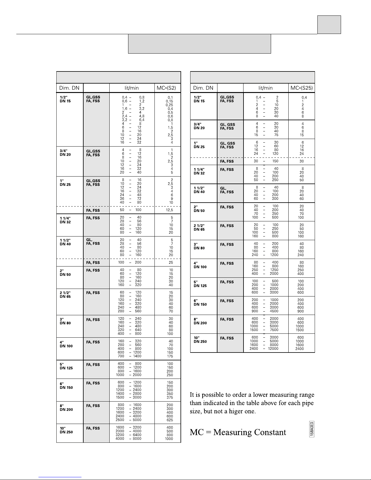
suits your specific application, as long as the new flow rate falls within the total possible span for the actual Flow Monitor (see section 6.1 page 29).
In each case of rebuilding the flow Monitor in the field, we kindly ask you to
consult Eletta or your local Distributor for advise of the right orifice plate before ordering.
First empty the piping system so it is un-pressurized and has no flow!
3
3.1
3.2
3

5041D2E18
20
For threaded model -GL:
3
For threaded model -GL:
Untighten the bolts that hold the Pipe Section between the flanges in the pi-
ping (do not remove the threaded parts from the piping). Remove only the
number of bolts necessary to pull the Monitor from the piping, normally it ta-
kes only one bolt from the highest position, to get the Monitor out. Take out
one of the spacers that holds the orifice plate. Change the orifice plate to the
new ordered orifice plate and remember that you can install it in any direction.
Reinstall the spacer that holds the orifice in place inside the Pipe Section.
Install the Monitor in the piping system again and tighten the bolts firmly to
avoid leakage.
For threaded model –GSS:
In this model there is no loose replaceable orifice plate and therefore it is necessary to change the complete orifice section with holder, to achieve a new
flow range.
Please follow the above instructions for the –GL model for dismounting the
whole orifice plate with holder. Remove the Control Unit from the old Pipe
Section (orifice section) and install this to the new Pipe Section. Remount the
Flow Monitor into the piping system again and tighten the bolts firmly.
For flanged model FA-:
Follow the procedure above to loosen the pipe section from the counter flanges in the piping system, but note that the spacers are held in place with two
screws, which has to be untightened before removal
For flanged stainless steel model FSS-:
In this model there is no loose replaceable orifice plate and therefore it is necessary to change the complete Pipe Section to achieve a new flow range.
Follow the procedure above to loosen the Pipe Section from the counter flanges in the piping system. Remove the Control Unit from the old Pipe Section
(orifice section) and install this to the new Pipe Section. Remount the Flow
Monitor into the piping system again and tighten the bolts firmly.
Always check that no gaskets will interfere, by misaligning, with the flow
when installing the Flow Monitor.
3
For threaded model -GL:
Untighten the bolts that hold the Pipe Section between the flanges in the pi-
ping (do not remove the threaded parts from the piping). Remove only the
number of bolts necessary to pull the Monitor from the piping, normally it ta-
kes only one bolt from the highest position, to get the Monitor out. Take out
one of the spacers that holds the orifice plate. Change the orifice plate to the
new ordered orifice plate and remember that you can install it in any direction.
Reinstall the spacer that holds the orifice in place inside the Pipe Section.
Install the Monitor in the piping system again and tighten the bolts firmly to
avoid leakage.
For threaded model –GSS:
In this model there is no loose replaceable orifice plate and therefore it is ne-
cessary to change the complete orifice section with holder, to achieve a new
flow range.
Please follow the above instructions for the –GL model for dismounting the
whole orifice plate with holder. Remove the Control Unit from the old Pipe
Section (orifice section) and install this to the new Pipe Section. Remount the
Flow Monitor into the piping system again and tighten the bolts firmly.
For flanged model FA-:
Follow the procedure above to loosen the pipe section from the counter flang-
es in the piping system, but note that the spacers are held in place with two
screws, which has to be untightened before removal
For flanged stainless steel model FSS-:
In this model there is no loose replaceable orifice plate and therefore it is ne-
cessary to change the complete Pipe Section to achieve a new flow range.
Follow the procedure above to loosen the Pipe Section from the counter flang-
es in the piping system. Remove the Control Unit from the old Pipe Section
(orifice section) and install this to the new Pipe Section. Remount the Flow
Monitor into the piping system again and tighten the bolts firmly.
Always check that no gaskets will interfere, by misaligning, with the flow
when installing the Flow Monitor.
When you change the orifice plate in order to get a new flow range, it is necessary to change the identification plate to a plate with the new range marked. This identification plate comes together with the orifice plate when you
3
Type plate and measuring constant
Untighten the bolts that hold the Pipe Section between the anges in the piping
(do not remove the threaded parts from the piping). Remove only the number
of bolts necessary to pull the Monitor from the piping, normally it takes only
one bolt from the highest position, to get the Monitor out. Take out the spacer
that holds the orice plate. Change the orice plate to the new ordered orice
plate and remember that you can install it in any direction. Reinstall the spacer
that holds the orice in place inside the Pipe Section. Install the Monitor in the
piping system again and tighten the bolts rmly to avoid leakage.
3

5041D2E18
21
order an orifice plate separately. You also have to attach another multiplication
label to the dial to suit the new range and this label also comes with the new
orifice plate.
3
order an orifice plate separately. You also have to attach another multiplication
label to the dial to suit the new range and this label also comes with the new
orifice plate.
If you have a direct reading dial installed instead of our standard, a new dial
must be specified and ordered with the new orifice plate.
Adjustment of switch point, S2 and S25
All the Eletta Flow Monitors are tested and calibrated according to the customers’ orders before shipping. If the customer does not specify a desired switch
point for the flow alarm, the S-series Monitor’s micro switches are preset to
trip at the min- and max flow value. Please note!! We have calibrated each
Flow Monitor in our flow rig and set the switches according to the Flow values we achieve in the rig under good conditions. We must stress that under actual field conditions, the flow profile can be different from the one in our flow
rig depending on valves, hoses, bends or other obstructions and therefore the
switching can be off from our preset values. There is a possibility to adjust the
switch/alarm points in the field by adjusting the micro switches’ position mechanically. To readjust, remove the two screws that hold the cover at the top of
the blue housing. The two adjusting dials are then visible through the opening.
Underneath the removed cover, you will find a small tool necessary to use in
order to change the adjusting dials position.
The adjusting dials are marked the same as the scale in the front and this marking can be used to approximately find the right switch/alarm point for the actual application. Put the tool inside the drilled hole on the top of the adjusting
dial and gently move the dial sideways to the desired position. If the two adjusting dials are set to the same position, the micro switches will trip at the
same time. If possible, use the left adjusting dial for the high flow alarm (higher end of the scale) and the right for the min. flow alarm (the lower end of the
scale), in order to get the best accuracy. If you use the alarms the other way
around, the spring mechanism inside the diaphragm housing will be affected
with lower accuracy as a result, so please try to avoid that.
Repeat the procedure for the next adjusting dial and then put the tool back in
its bracket at the cover.
If you have the possibility to check against a flow meter in the system, you
will get the best on site adjustment of the switch point.
Reinstall the cover at the top with the two screws and start up the process
again.
3
3.3
Dial
3

5041D2E18
22
3.4.1 Flow direction Selector (from January 2013)
3.4 Change of Flow Direction
Empty the pipe system so that it is un-pressurized and has no ow!
At the time of ordering, you must specify in which direction the Flow Monitor
shall be mounted i.e. from which side is the ow entering the Pipe Section and
how you would like to read the scale. (Please refer to g. 6 below for alternatives.)
If, for some reason, the Flow Monitor is ordered with the wrong ow direction,
it is possible to change this in the eld.
GL- and FA-models are delivered with a ow direction selector that can be used
for both directions.
To change the direction, loosen the four (4) hexagon screw, which hold the diaphragm housing to the Pipe Section. Remove the diaphragm housing and you
will see the ow direction selector (it might have attached itself to the bottom side
of the diaphragm housing). Replace the ow direction selector in the conguration
for your system (see g. 6).
Please also remember to turn the red arrow mounted on the Pipe Section
(-GL and –FA models), to align with the new ow direction.
Figure 6
3

5041D2E18
23
Change of Flow Direction
For GL-models, first empty the pipe system so that it is un-pressurized and
has no flow!
For FA-models, use the shut-off valves, see section 2.5
At the time of ordering, you must specify in which direction the Flow Monitor
shall be mounted i.e. from which side is the flow entering the Pipe Section and
how you would like to read the scale. (Pls. refer to fig. 6 below for alternativ-
es.) If, for some reason, the Flow Monitor is ordered with the wrong Flow di-
rection, it is possible to change this in the field. The flow direction selector
(only available in the -GL and -FA models. For -GSS and -FSS models we re-
fer to section 3.3 and 2.2) which is placed between the diaphragm housing and
the Pipe Section, determines the direction. There are two different selector al-
ternatives to choose from, the ”R” and the ” L” selector and you must use the
same selectors for all pipe section sizes. For mounting directions according to
alternative A,C and F (see fig. 6), use the ”R” selector. For B, D and E alter-
natives (see fig. 6), use the ” L” selector. The flow direction selector must be
ordered as a spare part, according to the right alternative.
3
3.4
Dial orientation and ordering code
Figure 6
3.4.2 Flow Direction Selector (until December 2012)
For GL and FA models there are two ow direction selectors to choose from,
the ”R” and the ”L” selector.
For mounting directions according to alternative A, C and F (see g. 7), use the
“R” selector. For B, D and E alternatives (see g. 7), use the “L” selector. The
ow direction selector must be ordered as a spare part, according to the right
alternative.
To change the selector, loosen the four (4) hexagon screws, which hold the
diaphragm housing to the Pipe Section. Remove the diaphragm housing and
you will see the ow direction selector, which is held in place by two screws.
Remove the screws and change the selector. Make sure that the four o-rings are
mounted correctly to avoid leakage. Mount the diaphragm housing to the Pipe
Section and tighten the four hexagon screws rmly.
Please also remember to turn the red arrow mounted on the Pipe Section
(-GL and –FA models), to align with the new ow direction.
For -GSS and -FSS models we refer to section 2.2.
Figure 7
3

5041D2E18
24
Change of Dial Orientation
As the Eletta Flow Monitors are not limited to a certain mounting position in
the piping system, the large visible dial can be mounted in several positions to
suit the application. (please refer to fig. 7). If you need to change the orienta-
tion in the field, please do as follows;
Note! Make sure that all electrical connections are set to power off before
starting the following procedure!
Remove the front glass with the four screws that hold it in place. Push the
pointer towards the dial and then upwards until the round hole in the pointer
matches the spindle coming out from the mechanism and then remove the
pointer. Undo the two screws that hold the dial and turn the dial 90° to the desired position and tighten the screws in the predrilled holes. Reinstall the pointer according to the new orientation with the reverse procedure from when it
was removed.
The spindle and the pointer has a square fitting which make s it possible to install the pointer in four (4) different positions and make sure that you put it
firmly in the right position for your application. When there is no flow
through the Monitor, the pointer shall point to the beginning of the red part of
the scale = zero position.
Note that a change of the mounting direction of the dial also can make it necessary to change the flow direction selector (see section 3.4).
3
3.5
3

5041D2E18
25
Trouble shooting
Verification of flow
We would like to stress the fact that all the Eletta Flow Monitors are calibrated
and adjusted individually on water in a specially purpose built calibrated flow
rig in our workshop. This means that we have calibrated/adjusted the Monitors
under reference conditions with enough straight runs before and after, always
the same liquid, temperature, flows and pressure. If you find our Monitors to
show another value compared to a reference meter on site, it can well be due
to the fact that the reference meter has been calibrated under other reference
conditions and that our Monitor have other conditions on site in the actual application, than we used under the calibration prior to shipping.
The Monitor is not showing any or the wrong value:
Is the Monitor mounted correctly with respect to the flow direction? Please
check the arrow on the outside of the pipe section with the actual (true) flow
direction For GL- and FA-models, check the flow direction selector inside
the monitor. Make sure that it is corresponding to the true flow, see 3.4.
Is there any flow in the pipe? And is it enough to create the needed ∆ρ?
Do you have the right orifice plate for the application? Check the stamped
values on the orifice plate. (pipe section model number and flow)
If you are using compression couplings into the Monitor inlet, check that the
inside diameter is enough to avoid the “nozzle” effect described above in
section 2.3 and also check the table for the minimum correct inner diameter
in the same section.
Are there enough straight runs upstream and downstream the Monitor? (10
diameters upstream and 5 downstream.)
Do you have valves or bends in more than one plane within the above
straight runs? If so, move the Monitor further away to achieve enough
straight runs.
Under the above section 3.1 it is described how the Monitor creates the differential pressure. Eletta Flow Monitors work with two different ∆ρ’s i.e. on the
V1 and S2 units the ∆ρ is always maximum 2000 mm H2O (196 mbar) and for
the V15 and S25 units, the ∆ρ is always maximum 5500 mm H2O (539 mbar).
This means that at maximum ∆ρ the flow is always 100% in any Flow Monitor
mounted on any pipe section.
mounted on a
4
4.1

5041D2E18
26
This makes it very easy to move one control unit from one pipe to another
Pipe Section on another pipe in order to check the function. It does not matter
what size the pipe section has, as we always work with the same ∆ρ on every
pipe size.
To check if the Monitor is showing the right desired and ordered value, it is
easy to remove the Flow Monitor from the pipe system and block the orifice
plate and apply the correct maximum pressure at the inlet. If you apply for example 2000 mmH2O (196 mbar) on the S2/S02series with a blocked orifice,
the pointer should reach the last digit (8 for the S2/S02) on the front scale and if
you have a direct reading scale installed, the pointer should reach the end value.
The same goes for a S25/S05 model, which should reach the digit 5 if you apply a pressure of 5500 mmH2O (539 mbar).
You can of course also verify the flow in the Eletta Flow Monitor versus another flow meter in the system or take the Monitor out and put in a flow test
rig, if you have the possibility.
If the above is not the case there is a need to send the Monitor to the
Distributor or directly to The Eletta Service department for control.
If you find process liquid/gas coming out of the Control Unit;
Most probably you will find a broken lever, the small stainless steel shaft
going through a rubber sealing and it is attached to the diaphragm in the end.
If you have exposed the Monitor to excessive pressure (over 16 bar/232PSI
standard) or if the process liquid/gas is too aggressive to the rubber in the sealing, it can cause the sealing to break.
Please check the identification plate/tag on the Monitor and write down the
serial number, flow range and liquid before ordering a new lever from your representative or us. If you have ordered a specially designed Flow Monitor i.e.
if it does not follow our standard execution, it must be checked what kind of
soft parts (diaphragm and seals) you have installed in the Flow Monitor. There
are three different kinds of rubber to order (see section 1.2 for details) and we
kindly ask you to provide us with the above information in order to help us
ship you the right material.
Electrical connections
Please always see to that you are using the right voltage and current (see section 1.2) and that you have connected all the leads in a proper way (see section
2.7). If you open the cover on the Control Unit of the Monitors it is normally
4
4.2
4

5041D2E18
27
4
4.3
very easy to see, if a component is broken/burned. If you find the micro switches are malfunctioning, it is possible to order new ones from Eletta Flow
or your representative and replace them on site.
If you need to order a complete Monitor or a Control Unit for any reason, please check the identification plate/tag and write down the serial number, flow
range and liquid and order a new Unit from us. We will ship you the complete
Control Unit with diaphragm housing and you can then easily fit the new
Control Unit to your existing Pipe Section with only four (4) screws, (please
see section 2.5 for details).
Spares
We are proud to say that our Flow Monitors are well known for their long lifetime and robust construction but inevitably, it is sometimes needed to order
spare parts. We refer to section 7 where you can find an exploded drawing
showing all replaceable components included in the Flow Monitor.
If you have installed the Eletta S-series Flow Monitor in a very critical application, we recommend you to have a complete identically precalibrated
Control Unit on stock, as it will only take removal of four bolts to change this.
The Pipe Section consists of no moving parts and all copper alloy/steel material and it is very rare with a break down of this part.
4

5041D2E18
28
5
Distributors
Eletta has appointed distributors around the world.
You find more information about which distributor to
contact on our website www
.eletta.com or call our
customer service.
Phone: +46 8 603 07 80
5
5041D2E18
29
6.1
Tables
Measuring Ranges
6
S2 and S02 S25 and S05
5041D2E18
30
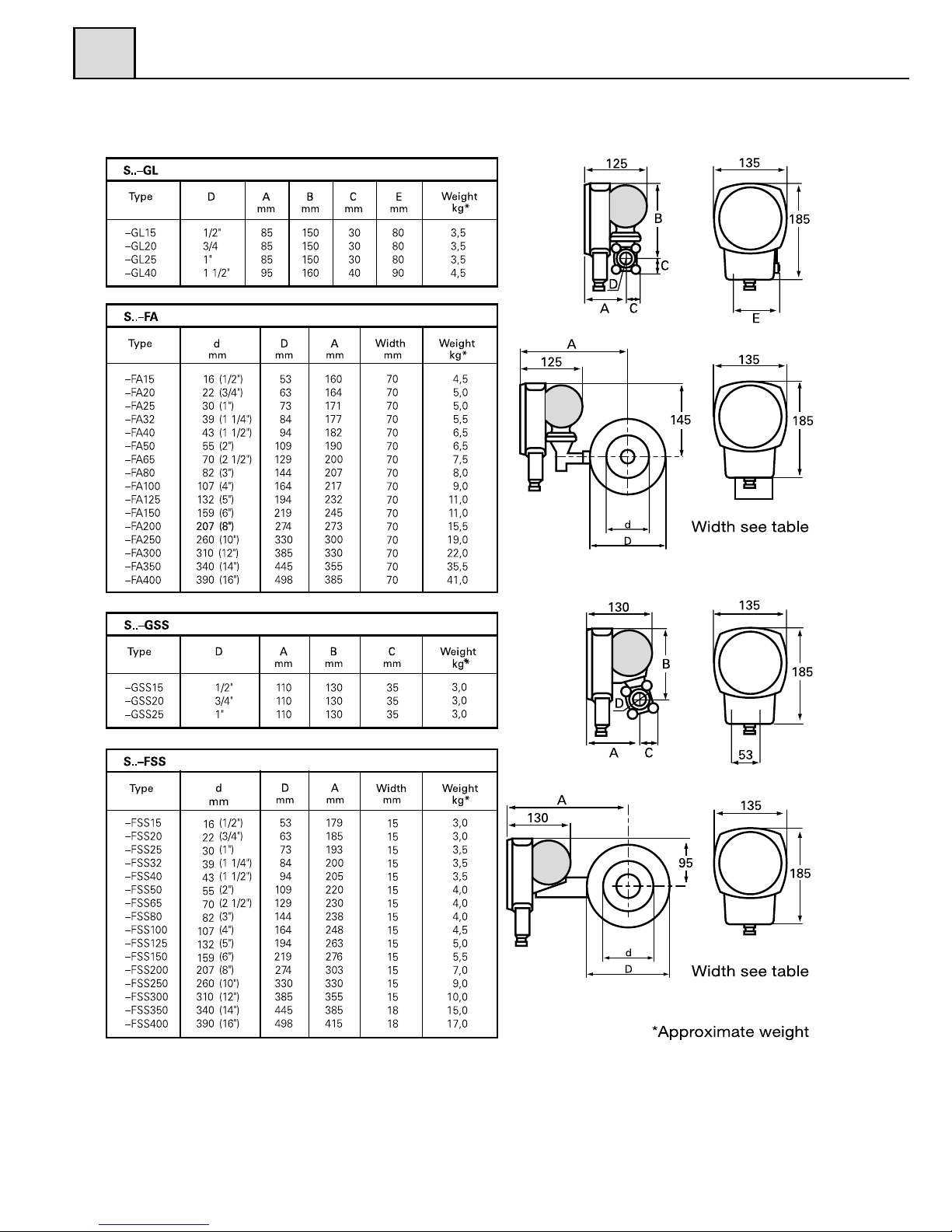
Weight and Dimensions
6
6.2
6
5041D2E18
31
7
Exploded drawing
S-GL/FA
7.1
1
2
3
4
5
6
7
8
9
10
11
12
13
14
15
16
17
18
19
202122
23
Screw
Dial glass
Clamp ring
Pointer
Dial
Adjusting dial
Cover
Screw
Tool
Casing
Lever/rubber seal
Diaphragm housing
Diaphragm
Diaphragm spring
Diaphragm cover
Screw
Fitting (Ventilation)
Cable gland PG16/PR 22,5
Connection box
Terminal block
Fitting
Screw with washer
Pointer mechanism
4
1
1
1
1
2
1
2
1
1
1
1
1
2
1
9
1
1
1
1
2
4
1
24
25
262728
29
30
31
32
33
34
35
36
37
38
39
40
41
42
434445
Microswitch 2
Spring bar 1
Screw
Pipe body GL
O-ring (orifice)
Orifice plate GL
O-ring (spacer)
Spacer GL
Threaded flange GL
Connecting unit FA
O-ring
Shut-off valve
Screw
O-ring
Pipe body FA
O-ring (orifice)
Orifice plate FA
Spacer FA
Screw and washer
Item Description Nos Item Description Nos
7
26
1
27
Screw, washer, nut 4
28 Pipe body GL
29 O-ring (orice)
30 Orice plate GL
31 O-ring (spacer)
32 Spacer GL
33 Threaded ange GL
34 Screw
35 Connecting unit FA
36 O-ring
37 Pipe body FA
38 O-ring (orice)
39 Orice plate FA
40 Spacer FA
41 Screw and washer
1
1
1
2
2
2
2
1
2
1
1
1
2
4
Flow direction selector

5041D2E18
32
7
5041D2E18
33
7.2
S-GSS/FSS
1
2
3
4
5
6
7
8
9
10
11
1213141516
17
Screw
Dial glass
Clamp ring
Pointer
Dial
Adjusting dial
Cover
Screw
Tool
Casing
Lever/rubber seal
Diaphragm housing
Diaphragm
Diaphragm spring
Diaphragm cover
Screw and washer
Fitting (Ventilation)
4
1
1
1
1
2
1
2
1
1
1
1
1
2
1
6
1
181920
21
22
232425
26
272829
30
313233
Cable gland (PG16/PR 22,5)
Connection box
Terminal block
Fitting
O-ring
Pointer mechanism
Microswitch
Spring bar
Screw
Orif
ice plate/Pipe unit FSS
Orif
ice plate/Pipe unit GSS
Threaded flange, GSS
Screw, washer, nut
O-ring
Manifold for FSS (Option)
Shut-off valve (Option)
1
1
1
2
2
1
2
1
2
1
1
2
4
2
(1)
(2)
Item Description Nos Item Description Nos
7
7

5041D2E18
34
7
7

 Loading...