

Elesta DOMOTESTA RDO353A series, DOMOTESTA RDO383A series User Manual
User manual: RDO3x3A
162515v44/11.10
Specifications are subject to change
1
User manual
DOMOTESTA
- RDO353A... V4.40
- RDO383A... V4.40
Weather- or room temperature-compensated
heating controller

User manual: RDO3x3A
2
Contents
1 General 3
1.1 Main functions 3
2 Safety regulations 4
2.1 Signs and notes 4
2.2 Correct usage 4
2.3 Authorised personnel 5
2.4 Product-specific dangers 5
3 Operation 5
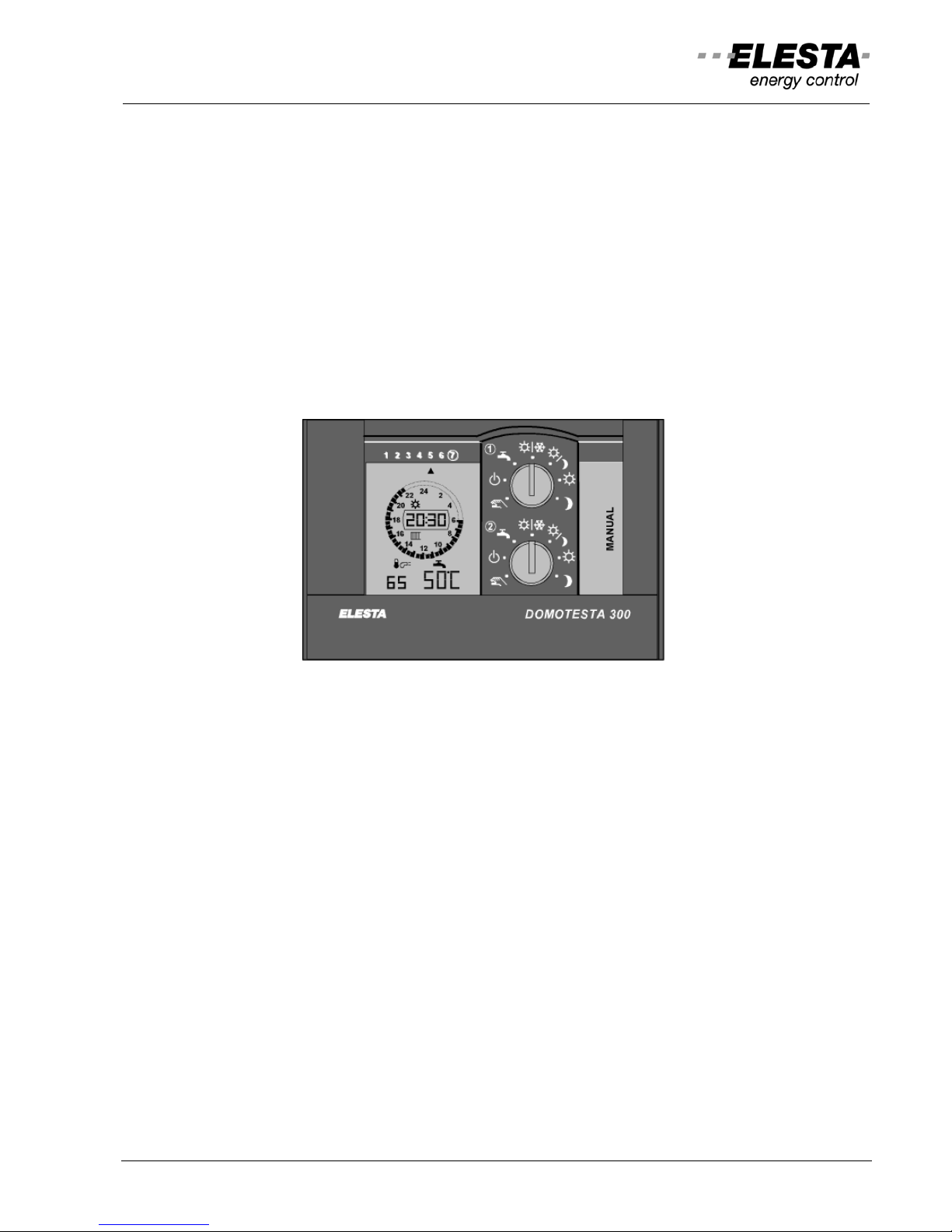
3.1 Operating elements 6
3.2 Display 6
3.3 Operation level l: Simple operation settings 8
3.4 Operation level ll: Advanced operation settings 10
4 Installation 15
4.1 Controller 15
4.2 Sensors 16
4.3 Accessories 18
5 Terminal assignment 19
5.1 Terminal designation 20
5.2 Controller RDO353A 21
5.3 Controller RDO383A 21
5.4 Heating circuit module RZM510A004 22
5.5 Boiler cascade module RZM530A004 22
5.6 DHW module RZM515A004 23
5.7 Address an parameter setting 23
6 Checklists 26
6.1 Initial start up 26
6.2 Trouble shooting 26
7 Expert level l: Parameter setting 28
8 Expert level ll: System test 45
9 Abbreviations 47
10 Protocol: Setpoints, time switch program, … 48
User manual: RDO3x3A
3
1 General
DOMOTESTA RDO heating controllers are consequently designed to the requirements of customers and
installers.
DOMOTESTA heating controllers exist in three different ranges:
RDO3xxA: With simple operation concept and LC display, able to communicate and network able
RDO2xxA: With simple operation concept and LC display, for standard applications
RDO1xxA: With analogic operation concept, for simple standard applications
The large LCD allows a comprehensive overview of all important information. A rotary knob each serve s
for operation-mode setting and temperature setpoint adjustment. All other functions are push-button
operated. This controller is especially designed for use in heating applications that involve cascade
operation, solar or district heating, gas heating or complex heating plants. Heating circuits are weather
compensated, DHW control is temperature guided. An optional room temperature sensor with or without
remote control unit allows automatic heating adaptation. Two configurable low-voltage outputs and freely
assignable digital inputs increase the functionality of the controller. The range-wide compatibl e terminal
assignment reduces wiring effort and eases application-specific controller selection.
It is available in following executions with different functions.
RDO353A000: 2-stage or modulating burner; boiler circulating pump,
1 mix-heating circuit (3-point valve and pump), DHW pump.
RDO383A000: 2-stage or modulating burner; boiler circulating pump,
2 mix-heating circuits (3-point valve and pump), DHW pump.
This manual contains in its front section all necessary information for the user concerning operation and
settings. The installer finds in the middle section details concerning installation and electri cal wiring. In the
back section is the list of parameters and the programming protocol. This protocol is to be filled in by the
service engineer.
Important:
This manual, together with the wiring diagram should be kept near the heating, easily accessible to the
service engineer. The controller has been developed for use with a great variety of systems. It is possible
that herein mentioned functions or accessories are not part of your heating system.
1.1 Main functions
Controller:
The controller consists in principle of three “independent” control circuits.
A heat generator, usually a boiler with burner or a heat pump or
solar collector with buffer storage, supplies the energy required.
The heating circuit (room heating) demands energy.
Its amount depends mainly on the desired room temperature,
the weather condition and the type of building.
The DHW heating demands energy.
It’s amount depends on the water temperature in the boiler
and hot water demand.
Generation of
heat energy
Room heating
Domestic hot
water heating
User manual: RDO3x3A
4
Additional control devices connected via the device bus (D-bus):
- Max. 6 heating circuit modules RZM510 (max. 7 heating circuits)
- Max. 3 DHW circuit modules RZM515 (max. 4 DHW pumps)
- Max. 3 boiler cascade modules RZM530 (max. 4 boilers)
- Remote control units RFB (max. 1 per circuit)
- Active room temperature sensors (max. 1 per circuit)
- Radio-controlled clock module (max. 1)
All devices are connected at terminals 21/22 (D-Bus). The wires are interchangeable.
Limitation of the device bus:
- Total cable length max. 200m
- Total number of devices max. 15 (pole-reversible)
2 Safety regulations
2.1 Signs and notes
The danger signs and notes shown below and used in this document refer to the following instructions.
Warning: A ”Warning” indicates actions or procedures which, if not performed correctly may lead to
personal injury or a safety hazard. Strictly observe the instructions supplied.
Caution:
A ”Caution” indicates actions or procedures which, if not performed correctly may lead to
faulty operations or destruction of the controller or system components. Strictly observe
the instructions supplied.
Note:
A ”Note” indicates actions or procedures to avoid unexpected results or as tips for
easier work. They include extra information for the user.
2.2 Correct usage
The product accompanying this manual complies with the technical regulations, valid at the time of
production, and with CE standards.
It may only be used in impeccable condition.
Please inform your service engineer if you notice any defect. In case of malfunction please switch the
controller off (mains fuse) and consult the checklist “Trouble shooting”.
This heating controller may only be used in the following applications:
- Heat production by oil or gas boiler, district heating or heat pumps
- DHW heating with hot water boiler
- Heating operation for direct and/or mix-heating circuit
All safety provisions specified by national or international regulations must be observed under all
circumstances:
- Regulations concerning electricity (mains current)
- Regulations concerning heating equipment
- Regulations concerning authorised personnel
User manual: RDO3x3A
5
2.3 Authorised personnel
Mounting, electrical installation, setting-up and maintenance of the device may only be carried out by
trained personnel, authorised by the operator of the facility. Personnel must absolutely and without fail
read and understand this manual before carrying out its instructions.
Any modification or alteration of the device is prohibited. Any work on the device (repairs, modifications)
may only be carried out by the manufacturer or bodies authorised by him.
2.4 Product-specific dangers
Touching of the terminal bars and fastened or unfastened wires directly or with conductive materials
constitutes the danger of electrical shock.
The controller terminal and/or wires may be supplied by external connections, even if the controller
seems not to be life (consult wiring diagram).
Before any work is carried out on electrical parts of the heating system (i.e. controller and/or burner,
pumps, switches, limiters, sensors, etc.), all mains fuses must be switched off.
3 Operation
Operation is performed on differently accessible user levels. Thus unwanted faulty parameter setting by
non-experts is prevented. During regular, undisturbed operation, the basic indication on the LCD info rms
of operation mode, errors or superimposed modes. Pressing of any key will switch on the illumination.
Further operation is described below. If there is no key pressed during a period of time, the display falls
back to basic indication and illumination is switched off.
The following user levels are available:
Operation level I:
Simple operation settings
With cover closed, only the operation modes: normal, reduced and frost protection as well as the
temperature setpoint adjustment may be set.
Operation level II:
Advanced operation settings
When the cover is opened, with basic indication on, additional modes, all time switch settings and
setpoint adjustments are accessible. Additional information about values and settings can be retrieved.
Expert level I:
Parameter setting
By means of special key sequences (from operation level II) the controllers basic parameters can be
altered.
Expert level II:
System test
By means of special key sequences (from expert level I) the relay functions of master and slave
controllers and can be tested.
This chapter describes the operation for the enduser.
(see also the mini guide "Manual" in the front panel of the controller)

User manual: RDO3x3A
6
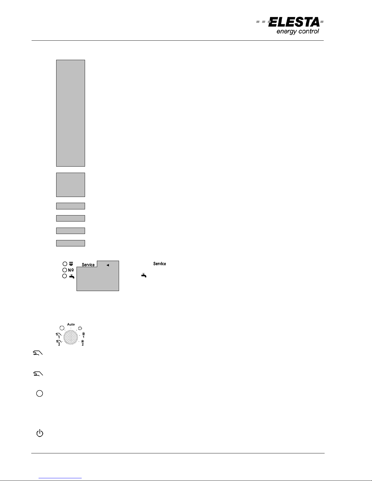
3.1 Operating elements
1 Mode switch=BA1
2 BA2 (temperature setpoint adjustment)
3 Service interface (PC)
4 Key " " : DHW charging
5 Key " " : Increase value
6 Key " " : Decrease value
7 Key " " : Parameter selection
8 Key " " : Weekday selection
9 Key "K" : Circuit selection [ / /...]
10 Key " " : Function selection
11 Display (LCD)
12 Fastening screws
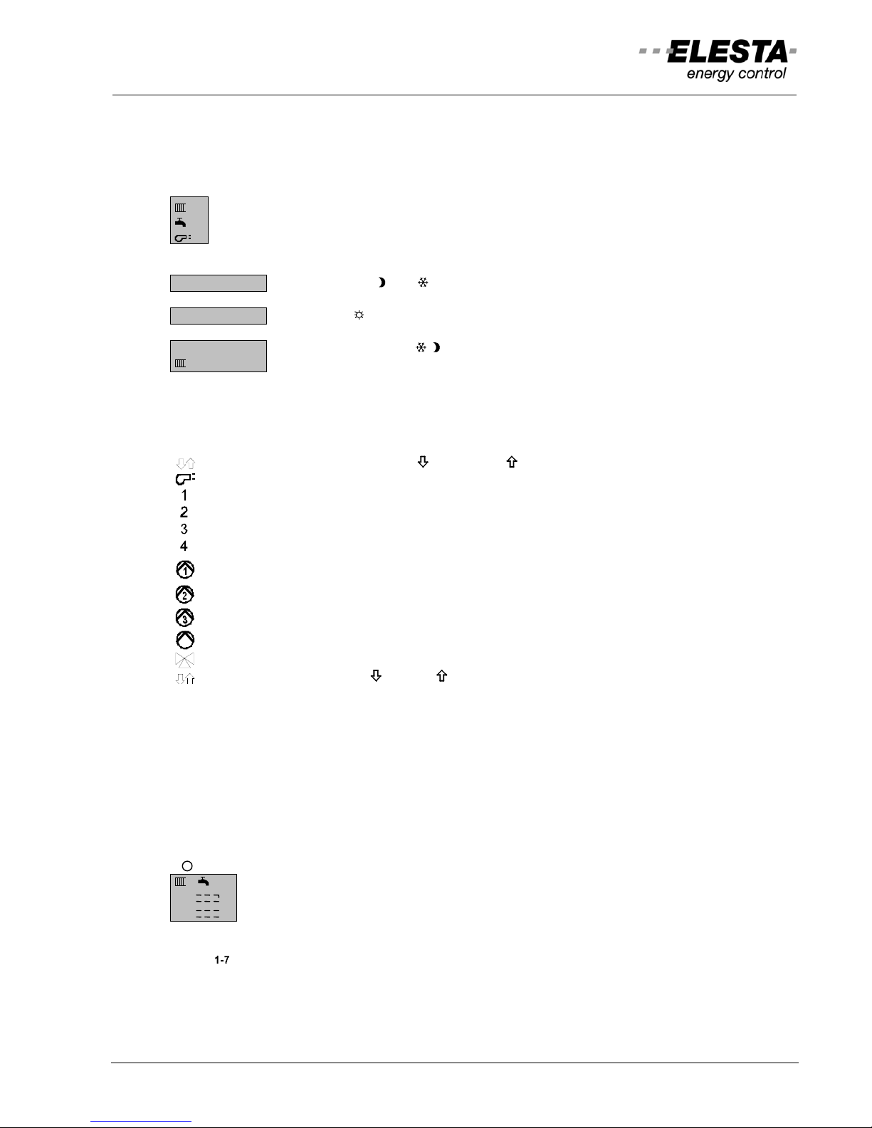
3.2 Display
Temperature indication:
: Outdoor temperature
: Boiler temperature
: Water temperature (DHW)
: Room temperature
Temperature setpoint indication:
Room
: Hot water:
: Anti-frost Anti-frost
: Reduced Reduced
: Normal Normal
flashing : Anti-legionella1
A : Display field 1
B : Display field 2
C : Status indicator (active outputs)
D : Reference symbol : heating circuit/ : DHW circuit
E : Time switch program (only ON-segments are visible)
F : Actual time
G : Active temperature setpoint ( )
H : Service mode activated ( )
I : Weekday indicator ( )
K : Automatic heating limit activated ( summer operation)
L : Function selector ( )
4
6
8
10
12
14
16
18
20
22
24
2
AB
C
D
E
F
G
C
H
IK
L
User manual: RDO3x3A
7
3.2.1 Display of special modes:
Special modes can be superimposed to the program by using push-buttons at the controller or the remote
control unit or via external inputs. Thus different temperature setpoints may be activated.
Superimposed modes (flashing symbols):
: Heating circuit
: DHW heating circuit
: Boiler circuit (heat generator)
Special mode (displays 1 and 2):
EC 6h
Economy mode: " " or " " active for the indicated time period.
PA 3h
Party mode: " " active for the indicated time period.
HO 15.02
Holiday mode: Setpoint / active. Heating will be resumed
1
on the morning of the indicated date.
3.2.2 Indication of the system status:
These symbols represent the system status. They appear when the corresponding device is activated.
Burner 1 modulation commands ( INCREASE/ DECREASE)
Heat generator symbol (burner etc.)
Heat generator stage 1
Heat generator stage 2
Output PWM1 active
Output PWM2 active
Pump 1 (direct heating circuit)
Pump 2 (DHW charging)
Solar pump
Pump MK (mix-circuit)
Symbol for mixing valve
Mixing valve commands ( CLOSE/ OPEN)
3.2.3 Indication of errors:
When an error occurs, it will be recorded on the internal error list and indicated by the flashing display
fields 1 and 2. It will only be shown this way, on the basic indication and only as long as the error is
present. (serious errors must be acknowledged first by pressing a key). The error list records only the 10
most-recent errors. The older ones will be overwritten. An error that is already on the list, will not be
recorded twice. (see operation level II: chapter 3.4.7 ”Display service data” function “Service”: parameters
90..99).
Error status display of sensors at "Service" function:
K
: Switching to the next circuit (boiler, heating or DHW-circuit)
1 : Display number of boiler, heating or DHW-circuit
xx : Sensor number xx is short-circuited
xx : Sensor number xx is broken
Erase errors on base display, if possible:
Press " ".
User manual: RDO3x3A
8
Error numbers and description:
Sensor or function errors:
X
= 1..7 Heating circuit (1..7)
YY
= 11..14 Heat generator (burner 1..4)
YY
= 21..24 MCBA14..-errors (MCBA 1..4)
Y
= A..d LMU64..-errors (LMU64 1..4)
ZZ
= 31..34 DHW circuit (1..4)
Er ZZ_1
: DHW temperature sensor 1 defective (boiler)
Er ZZ_2
: DHW temperature sensor 2 defective (boiler)
Er ZZ_3
: DHW temperature sensor 1 defective (mixer)
Er ZZ_4
: DHW temperature sensor 2 defective (mixer)
Er X10
: Outdoor temperature sensor defective (RZM)
Er 11
: Outdoor temperature sensor 2 defective (Ba2)
Er X12
: Room temperature sensor defective
Er X14
: Flow temperature sensor defective
Er YY20
: Return temperature sensor defective
Er YY21
: Boiler temperature sensor defective
Er YY23
: Flue gas temperature sensor defective
Er 24
: Buffer storage temperature sensor 1 defective
Er 25
: Buffer storage temperature sensor 2 defective
Er 27
: Return temperature sensor (district heating for DHW) defective
Er 28
: Collector temperature sensor defective
Er YY30
: Flue gas temperature exceeded
Er YY31
: Burner malfunction, reported via aux. input
Er 5x : Controller malfunction
Er ..6x : Device bus conflicts during installation or operation
Er 7x : Field bus errors during installation or operation
Er 8x : Interface errors
Erase error memory:
: Select field " "
90 YYXX
: Select parameter 90
90 YYXX
: Press " " for 5 seconds
S-Er
: Error memory erased
90 0
: Error memory is not accessible if empty
3.3 Operation level l: Simple operation settings
3.3.1 Mode switch 1 for boiler cascades:
When the controller is used in configuration boiler cascade the symbol plate with
symbols is fitted!
2 Manual operation mode 2: Burner on step 2 or modulation command full power. Boiler pump is on. The
mixing valve output (return) is on pause DHW charge is released (emergency operation).
1 Manual operation mode 1: Burner on step 1 or modulation command minimum power. Boiler pump is
on. The mixing valve output (return) is on pause. DHW charge is released (emergency operation).
OFF: Boiler OFF, no frost protection. Burner, boiler pump and DHW charge are off. Mixing valve
command approximately 10 minutes "open", then pause.
AUTO Automatic mode: Regular operation of all circuits and release of DHW charge according to the time
switch program.
Standby mode: Boiler OFF, frost protection is active. Burner, boiler pump and DHW charge are off.
Mixing valve command approximately. 10 minutes "open", then pause
.
User manual: RDO3x3A
9
1 Service mode 1: Burner on stage 1 or modulation command full power. Boiler pump is on. The mixing
valve output (return) is in operation. DHW charge is permanently on
.
2 Service mode 2: Burner on stage 2 or modulation command to minimum. Boiler pump is on. The mixing
valve output (return) is in operation. DHW charge is permanently on.
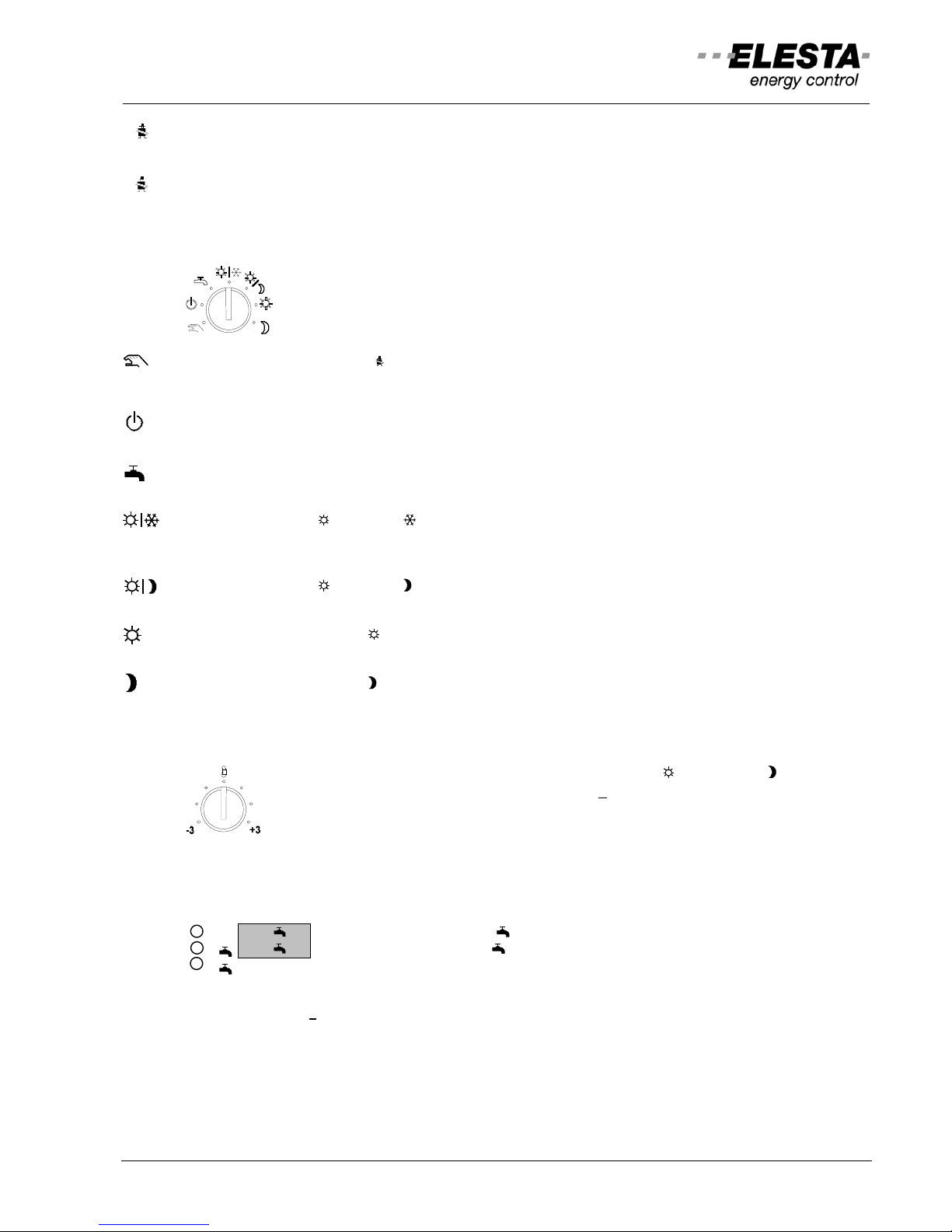
3.3.2 Mode switch 1/2:
Depending on the controller configuration it might be fitted with 1 or 2 such switches.
Operation Switch 1 is always for heating circuit 1 and/or heat generator. Switch 2 is
commanding heating circuit 2.
Manual and service mode ( ): Burner and heating circuit pumps are on. The mixing valve output is on
pause. DHW charging is permanently released (emergency operation).
Solar operation: Collector pump 3 min. on minimum speed, then automatic.
Standby mode: Heating and DHW charge OFF (frost protection is active). Solar operation: Controller
remains on.
Summer operation mode: Heating OFF (frost protection is active). The DHW charge is released
according to the time switch program
.
Automatic mode (" normal"/" frost protection") according to the time switch program. During the
OFF-period the lower setpoint for frost protection is active. DHW charge is released according to the time
switch program
.
Automatic mode (" normal"/" reduced") according to the time switch program (back-up mode
during lowering). DHW charge is released according to the time switch program
.
Continuous operation with normal temperature setpoint. The time switch program for heating circuits
is not active. DHW charge is released according to the program
.
Continuous operation with reduced temperature setpoint. The time switch program for heating
circuits is not active. DHW charge is released according to the program
.
3.3.3 Temperature setpoint adjustment
This rotary knob is to adjust the temperature setpoint for “ normal” and “ reduced”
operation. The preset value can be adjusted by +
3K. Adjustments set at an available
remote control unit are superimposed to each other
.
3.3.4 Single DHW charging
The DHW can be charged independently of the time switch settings. Is no demand for DHW charging i.e.
boiler temperature is high enough, this function is terminated automatically
.
K 2
: Select DHW circuit e.g. [2 ]
2
: Release DHW charging; " " flashes
: Switch selection OFF
3.3.5 Number key: No
At the basic indications, the controller type and the SW version number are displayed when this key is
pressed
.
3.3.6 Circuit key: K
At the basic indications, this key switches the display to consecutive circuits of heating, boilers and DHW.
User manual: RDO3x3A
10
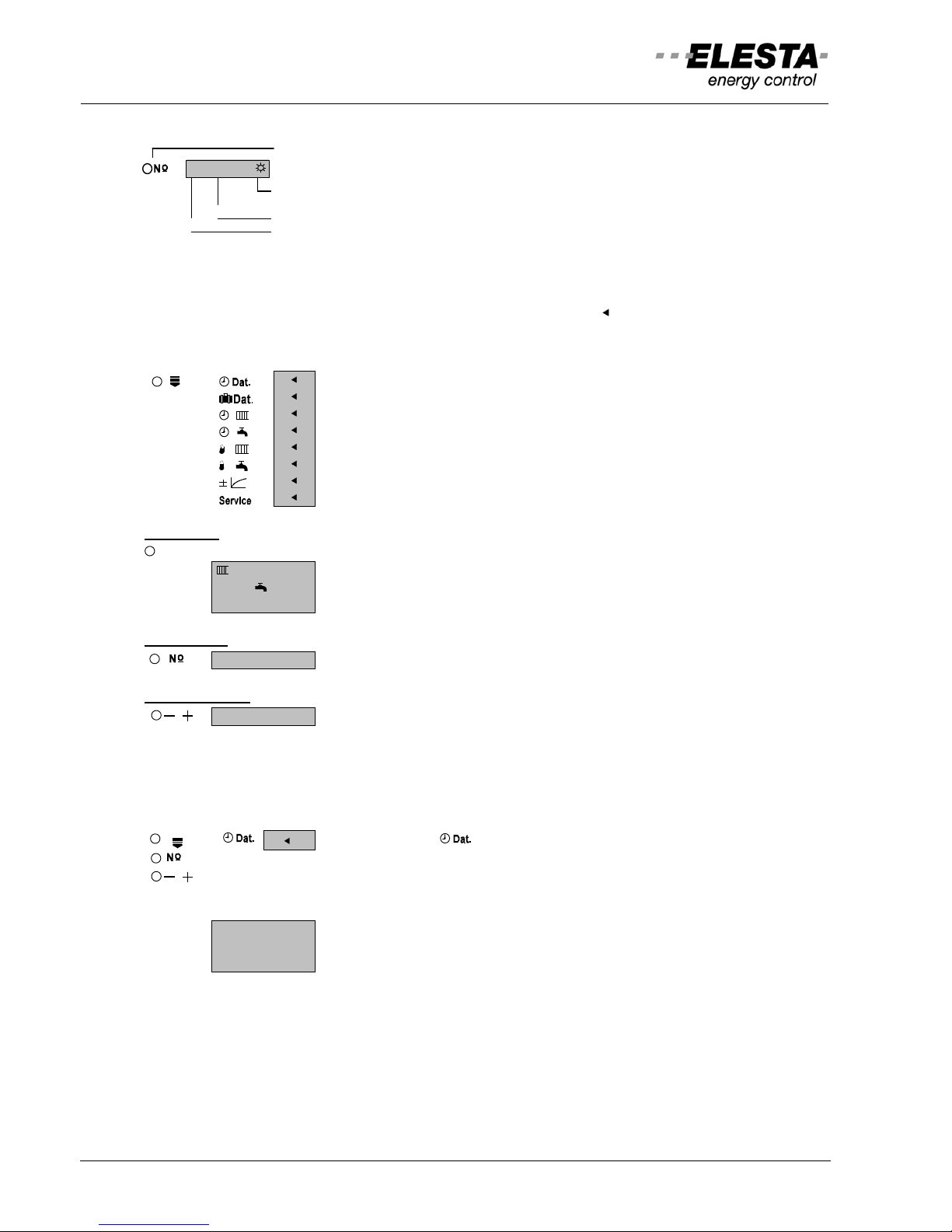
3.4 Operation level ll: Advanced operation settings
Press key to select function
1 20.30
Additional symbols in the display
Parameter value (LCD: Display at lower right)
Parameter number (LCD: Display at lower left)
3.4.1 Operation at operation level ll
Operation level II is activated by the function selector key. The cursor “ “ appears and moves downwards
on every keystroke. As long as the cursor points to a function, operation level II is active.
Functions which can be selected with the function selection key:
: Time, date, year
: Holiday (absence) program
: Time switch program: Heating circuits
: Time switch program: DHW (& independent. time switch)
: Temperature setpoints heating circuits
: Temperature setpoints DHW circuits
: Heating characteristic adjustment
: Display temperatures and service data
Circuit key
K
: Circuit selection and display
2
: Heating circuit with number
2
: DHW-circuit with number
3
: Boiler- or heat generator circuit with number
Number key
1 20.30
: Parameter selection; (field 1 e.g."1")
Minus/Plus key
/
1 20.30
: Changes value: field 2 e.g. "20.30"
Only values that are flashing may be altered.
3.4.2 Set time and date
For satisfactory operation, the correct time, date and year must be set!
: Select function " "
: Select the next parameter
/
: Change value
Parameter number and value:
1 20.30
: Time (hours.minutes)
2 20.01
: Date (day.month)
3 1998
: Year
User manual: RDO3x3A
11
3.4.3 Holiday program
6 Holiday blocks can be programmed. Odd parameters (1, 3, 5, ...) represent absence start,
(temperature setpoint “ =frost protection” or “ =reduced”) and even parameters (2, 4, 6, ...) represent
the resume date (temperature setpoint “ =normal”). DHW charging is disabled, when all heating circuits
are in frost protection mode (i.e. no heating needed).
Note: With the program " normal/reduced" the setpoint reduced is valid during vacations.
: Select function "
"
K
2
: Select heating circuit [
2]
Activating the holiday program:
1 - -.- -
: Select unused block (odd)
/
1 29.01
: Enter first day of absence
2 30.01
: Select block end (even)
/
2 15.02
: Enter resume date
3 - -.- -
: Select next block as required
Deactivate single block:
2 15.02
: Select date of return (even)
1 - -.- -
: Press key "-" until block erased
Clearing all blocks:
1 29.01
: Press "
" for 5 seconds
1 - -.- -
: Holiday programs erased
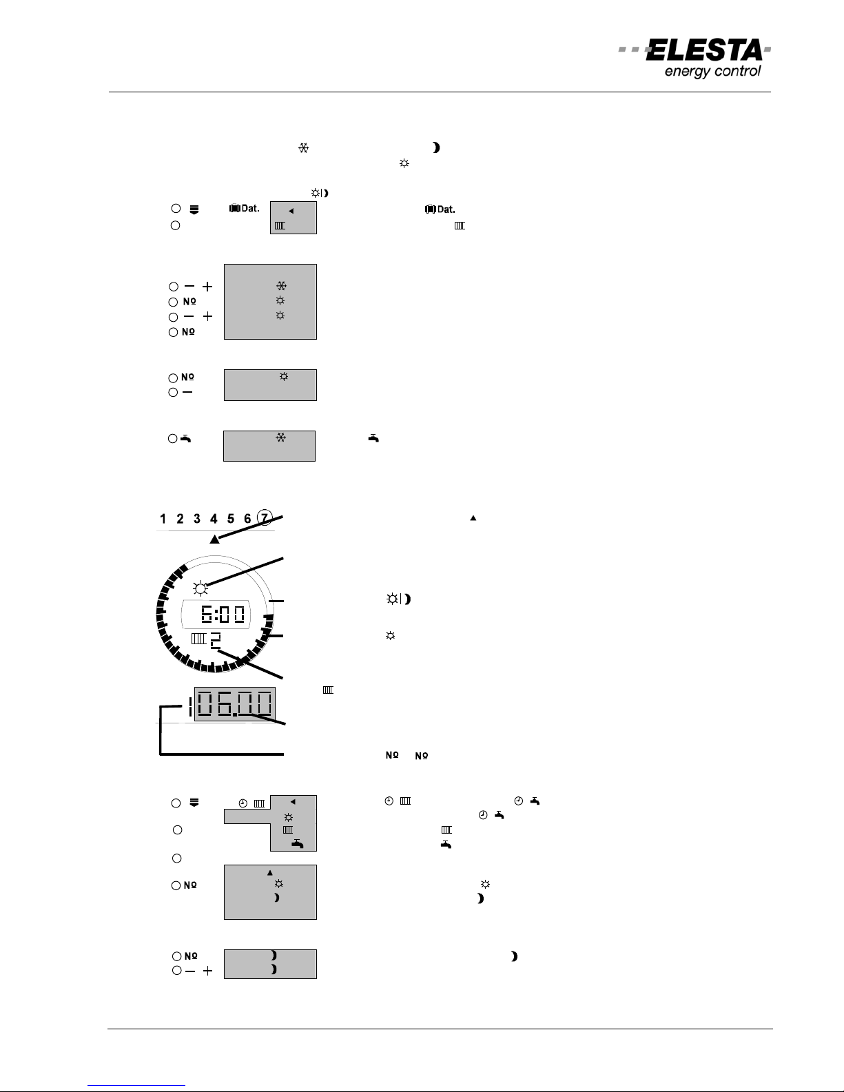
3.4.4 Set time switch program
Weekday indicated by cursor " "
Operation mode at the time indicated
(e.g. normal)
Time segment " " for reduced operation
Time segment " " for normal operation
Circuit selected (time switch program)
(e.g.
2=heating circuit No. 2)
Switching time
Switching point ( =number)
Display set switching points
:
: Function: " " heating circuit or " " hot water
1 07:00
(independent time switch at " ", display: 9)
K
2 : Select heating circuit [ 2]
2 : Select DHW circuit [2 ]
1-7
1234567 : Select weekday; 1=Monday..7=Sunday (cursor)
(cursor move)
1 06.00 : Select switching point; (odd " =normal")
2 22.00 : Next switching point; (even " =reduced")
3 - -.- -
: Next available (6 switching points available)
Modify switching points:
2 22.00
: Select appropriate switching point " =reduced"
/
2 13.30
: Modify time
4
6
8
10
12
14
16
18
20
22
24
2
User manual: RDO3x3A
12
Add switching points:
3 - -.- -
: Select next unused switching point "- -.- -"
/
3 16.00
: Set desired time; e.g. 16:00 " =normal"
4 16.15
: Select next switching point
/
4 22.00
: Set desired time; e.g. 22:00 " =reduced"
Erase switching point:
4 22.00
: Select even switching point
3 - -.- -
: Press key "-" until cycle erased
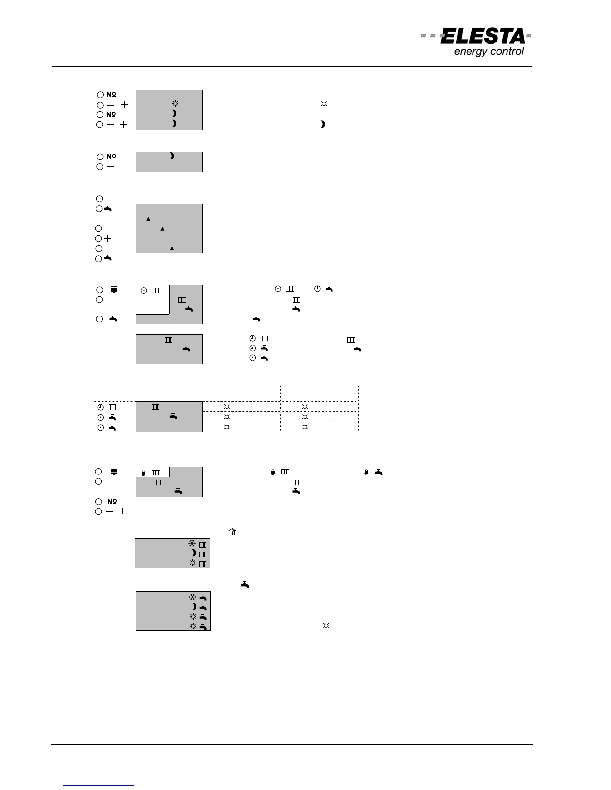
Copy switch cycles of weekday:
: Select weekday (source) with cursor
COPY
: Copy/read program; "COPY" is displayed
: Source weekday is displayed
: Select weekday (target): cursor flashes
: Copy/paste program to weekday
: Select next day (target), etc.
: Terminate copy function
Recall standard program: (
factory settings)
: Select function: " " or " "
K
2 : Select heating circuit [ 2]
2 : Select DHW circuit [2 ]
COPY
: Press key "
" for 5 seconds; "COPY" is displayed
After 5 seconds one of the following appear:
S-UH 2 : Function " ": Standard program 2 loaded
S-Ub 2 : Function " ": Standard program 2 loade d
S-UF 9
: Function " ": Standard program independent time switch loaded
Standard program: (factory settings)
Field: Displ ay: 1-5 (MO-FR) 6-7 (SA-SU)
2
7:00 -23:00 8:00 -23:00 (HK-time switch)
2
6:30 -20:00 7:30 -21:00 (DHW-time switch)
9
6:30 -20:00 7:30 -21:00 (independent time switch)
3.4.5 Adjust temperature setpoints
: Select function " " heating circuit or " " DHW
K 2 : Select heating circuit [ 2]
2 : Select DHW circuit [2 ]
: Select parameter
/ : Modify the setpoint
Standard room temperatures:
1 10.0°C
"Frost protection" (minimum temperature 5°C)
2 15.0°C
"reduced"
3 20.0°C
"normal"
Standard DHW temperatures:
1 5°C
"Frost protection" (minimum temperature 5°C)
2 5°C
"reduced"
3 55°C
"normal"
4 65°C
"anti-legionella", if released ( flashes if running)
1-7
1-7
1-7
User manual: RDO3x3A
13
3.4.6 Correct room temperature deviation
If the actual room temperature deviates from the setpoint after several hours of operation, the internal
reference can be adapted as follows:
: Select function " "
K
2 : Select heating circuit [
2]
1 20.3°C
: Temperature is displayed
/
1 19.8°C
: Enter the measured temperature
Recall the standard heating curve:
1 19.8°C
: Press key " " for ca. 5 seconds
S----H
: Standard heating curve is loaded
Attention:
- This adaptation should be made once each at low and at high outdoor temperatures. Thus the heating
characteristic is adapted correctly.
- It will only be available once a day
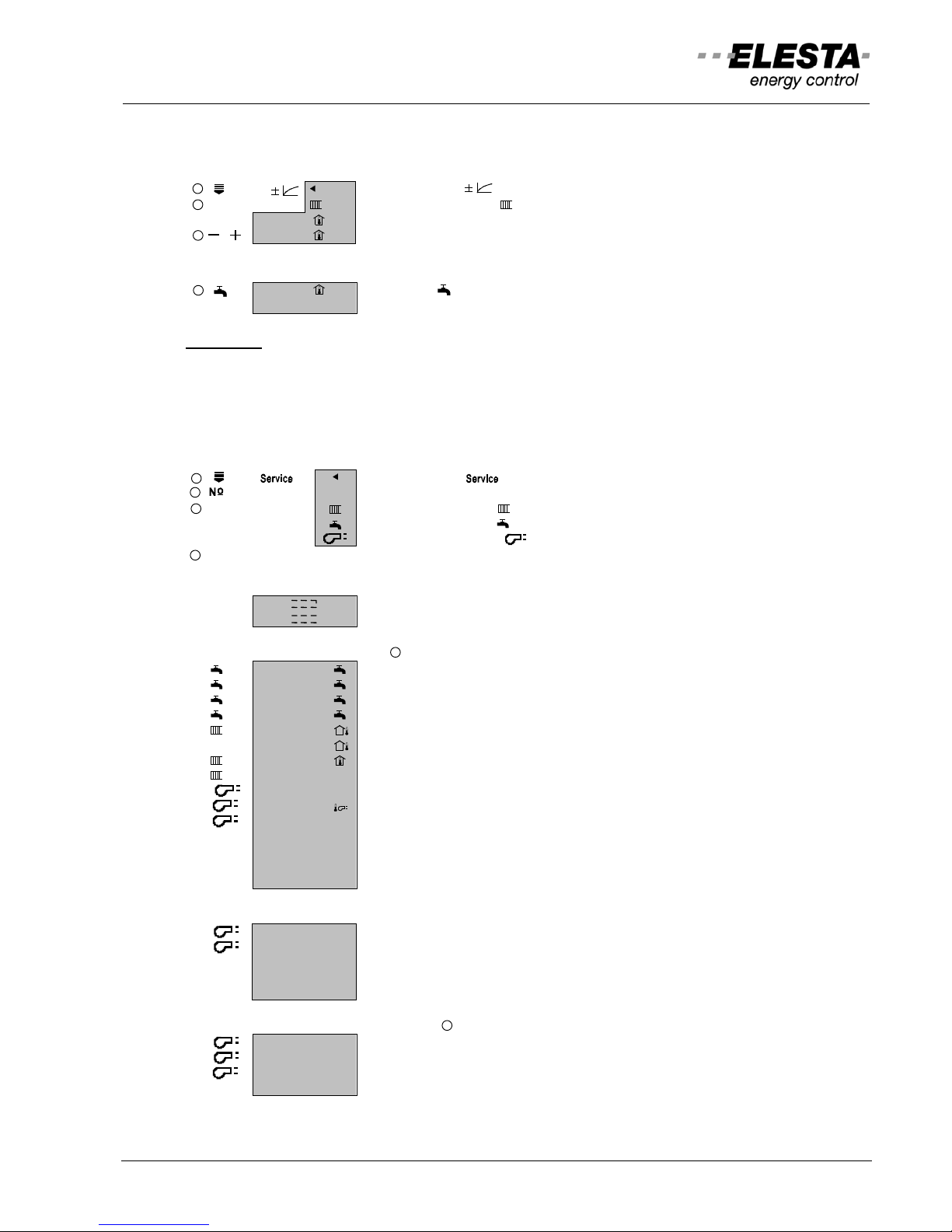
3.4.7 Display service data
Values are displayed only if the sensors are connected:
: Select function " "
: Select parameter
K
: Select heating circuit [
2]
: Select DHW circuit [2
]
: Select heat generator ( )
* : Key pressed -> displays setpoint *
Error status display of sensors:
xx °C
: Sensor number xx is short-circuited
xx °C
: Sensor number xx is broken
Temperatures: * : Displays setpoint *
* 1 55°C
: DHW temperature 1 *
* 2 53°C
: DHW temperature 2 *
* 3 58°C
: DHW mixing valve 1 *
* 4 65°C
: DHW mixing valve 2 *
* 10 -5°C
: Outdoor temperature
11 -5°C
: Outdoor temperature 2
* 12 20.1°C
: Room temperature *
* 14 52°C
: Flow temperature * (respective boiler temperature)
20 45°C
: Return temperature *
*
21 60°C
: Boiler temperature *
*
23 95°C
: Flue gas temperature (*max. flue gas temperature)
* 24 75°C
: Buffer storage temperature 1 *
* 25 75°C
: Buffer storage temperature 2 *
* 27 45°C
: Return temperature sensor (district heating w. 2 HE) *
* 28 163°C
: Collector temperature (* differential value)
Heat generator operating hours, etc.:
30 1675
: Heat generator stage 1, total running time [hours]
31 347
: Heat generator stage 2, total running time [hours]
34 2535
: Collector pump, total running time [hours]
35 12.20
: Collector power [kW]
36 1590
: Collector energy total [kWh]
Heat generator start cycles: * : Displays setpoint *
40 630
: Heat generator stage 1 (value x 10)
41 150
: Heat generator stage 2 (value x 10)
*
45 50
: Actual boiler power of boiler [%]
* 46 30
: Actual cascade boiler power [%]
1-7
1-7
1-7
User manual: RDO3x3A
14
Additional data:
81 63.00
1130
: Totalized 1: counter 1 x factor 1 (split indication: low value)
High value: (at clock segment) [total: 113063.00]
82 93.00
0245
: Totalized 2: counter 2 x factor 2 (split indication: low value)
High value: [total=24593.00]
85 50
: PWM1 (speed collector pump, output 0..10V, etc.) [%]
Error list:
For error codes see chapter: 3.2.3 "indication of errors".
The error list records only the 10 most-recent errors. The older ones will be overwritten. An error that is already on
the list, will not be recorded twice.
90 YYXX : Most recent error and code
: YY = 1..7 Heating circuits (1..7)
: YY = 11..14 Generator circuit (boiler 1..4)
: YY = 21..24 Gas boiler controller (MBCA 1..4)
: Y = A..d Gas boiler controller (LMU64 1..4)
: YY = 31..34 DHW circuits (1..4)
: XX = Number of the error code (XXX for LMU64 error codes)
99 YYXX : Earliest error entry
Clearing error list:
90 YYXX
: Press key " " for ca. 5 seconds
S-Er
: Error list being cleared
90 0
: Error list empty
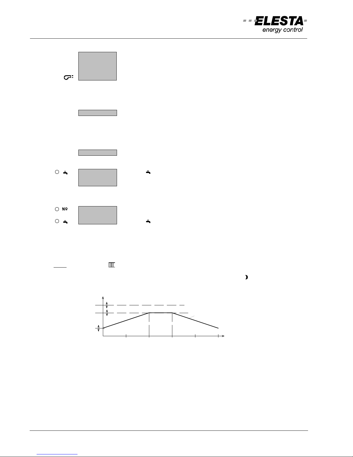
3.4.8 Floor dry up program
A2 0 °C
: Select parameter A2
A2 50 °C
: Set the maximal heat-up temperature
A2 x
: Press key " " for ca. 5 seconds
Sequence
- 6 Days: Flow setpoint continuous from Par.160 to Par.A2
- 3 Days: Par.A2
- 6 Days: Flow setpoint continuous from Par.A2 to Par.160,
followed by end of program and normal regulation
Note:
Symbol flashes during operation
Flow setpoint and program duration are displayed.
The program is active for all circuits, their mode switch stand on "
reduced". DHW charge
is released. An upload of the saved sequence data is possible with the PC program „RDO
History Import“.
time (days)
369
12 15
Par.151
Par.+92
Par.160
Flow temperature
set point
User manual: RDO3x3A
15
96
144
max. 9 mm
15
138
92
- 0
+1
- 0
+0,5
101
66
66
81
137
91
2,5
51
49
31
RZB521A
4 Installation
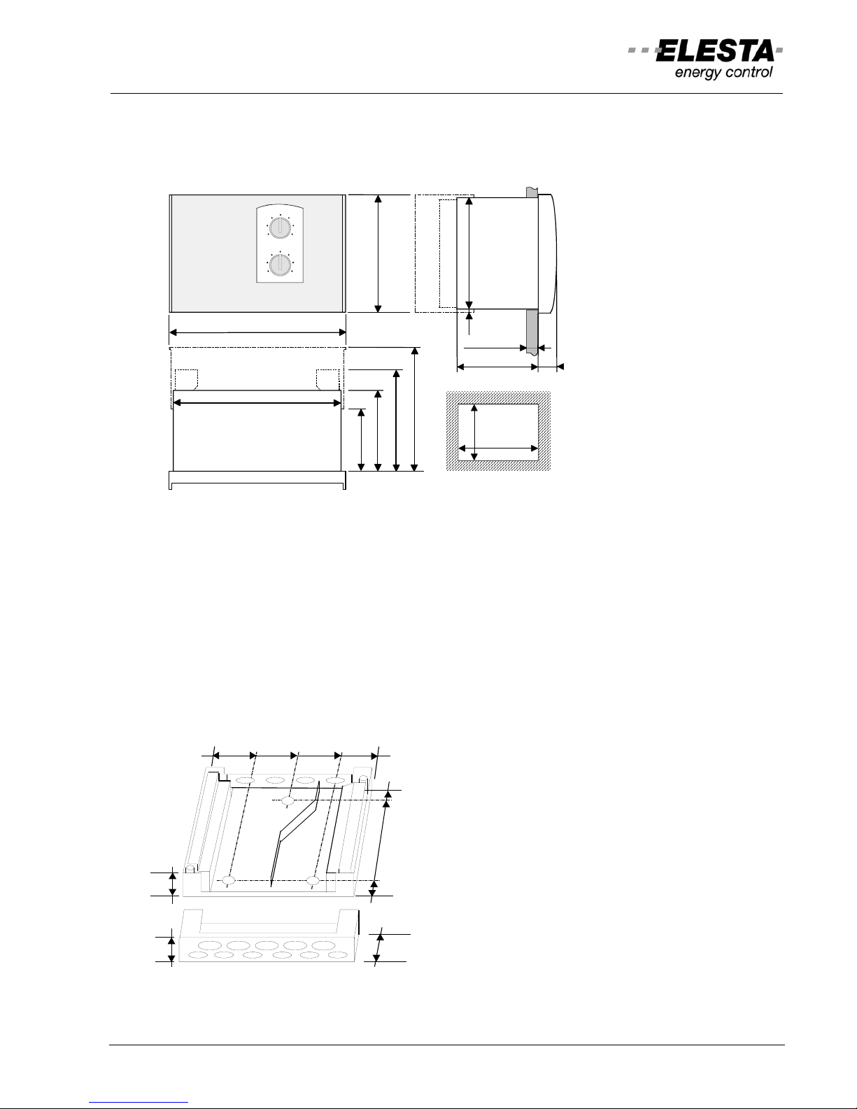
4.1 Controller
4.1.1 Dimensions
4.1.2 Mounting
Flush mounting:
Slide device into panel cut-out and secure it with fastening bolts. Wire with connectors for AMP male
connectors RZB500A and RZB501A, screw able connectors RZB510A and RZB511A (or base plate
RZB520A with RZB511A).
Wall mounting:
Mount base plate RZB520A and wire it. Plug device on and fix it. (RDO383A requires RZB511A)
DIN-rail mounting:
Screw rail clamps RZB106A for DIN rail 35mm onto base plate RZB520A.
Snap base plate onto DIN rail and wire it. Plug device on and fix it.
Base plate and extension of terminal compartment:
RZB520A: Base plate with 2 side walls (for glands 4xPG9)
with screw able connectors RZB510A in position.
RZB521A: Extension kit for terminal compartment. Fits to
top or bottom of base plate RZB520A, for glands 6xPG9 and
5xPG11, with slide covers.
50
40
14472 104
80
96
16
RZB 520A
User manual: RDO3x3A
16
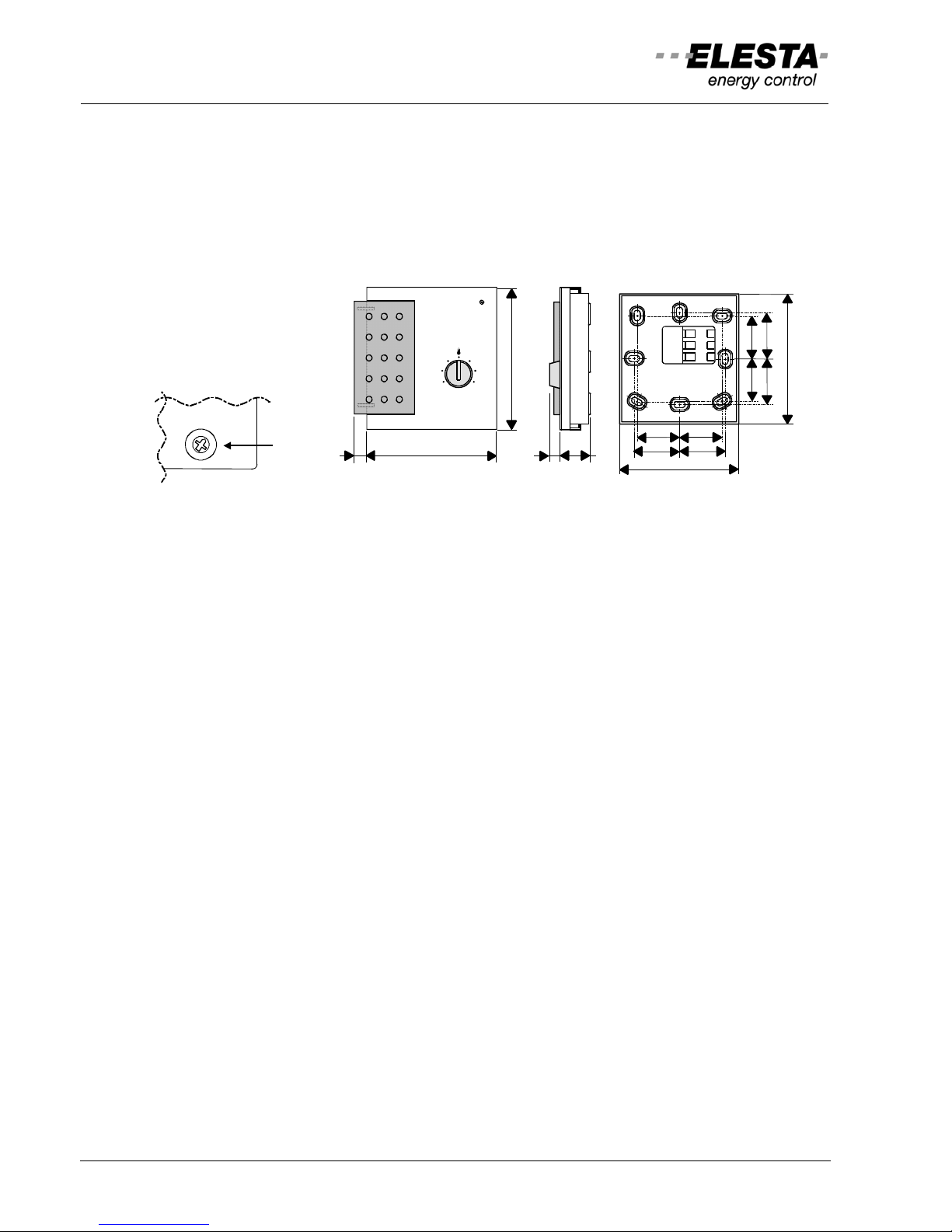
4.2 Sensors
4.2.1 Remote control unit, room temperature sensors
For residential area only. Not to be exposed to sun or other heat sources (chimney, radiators, draughts,
TV-set, lamps); not behind furniture or curtains; ca. 1.2-1.5m height; seal installation conduit. Use
breakthroughs in housing base for drilling the fixing points. The address of the remote control unit must
be set identical to the address of the corresponding mix-heating circuit (factory setting: Address=1). Total
length of the devices bus max. 200m. Cable 2x1mm
2
(flex type for max. length), unshielded, separated
from mains lines. Minimize use of conduit- or connector-boxes.
Device bus:
With address selector
Remote control unit RFB510A: (active, connected to device bus)
Remote control unit with temperature sensor: Program selection by sliding switch, temperature setpoint
adjustment, status display (LED)
Remote control unit RFB520A: (active, connected to device bus)
Remote control unit with temperature sensor: Program selection by single key, temperature setpoint
adjustment, status display (LED)
Comfort remote control RFB540A: (active, connected to device bus)
Remote control unit with temperature sensor: Program selection, LCD-indication
Room temperature sensor RFT510A: (active, connected to device bus)
Active room temperature sensor without control elements
Room temperature sensor RFT410A: (NTC 10kΩ; at 25°C)
Passive room temperature sensor without control elements
4.2.2 Wireless devices, remote control unit
Receiver unit RZM610A010: (active, connected to device bus)
For the devices as follows:
Wireless remote control unit RFB610A010
Heating applications with room sensor, program selection, temperature setpoint adjustment, LCD-display
Wireless output sensor RFT620A010
Actualisation of sensor values every 30 minutes
7 20
1
3
2
28 28
30
30
30
30
28
28
79
86
8 85
94
-3 +3
0
1
2
3
4
5
6
7
8
9
ADR
 Loading...