

Elesa DD51-E Instructions For Use Manual
Direct drive electronic position indicators
2.0 Software Version
INSTRUCTIONS FOR USE
DD51-E
ELESA S.p.A. Via Pompei, 29
•
20900 Monza (MB) Italia • Tel. +39 039 2811.1 • Fax +39 039 836351 • info@elesa.com
Art. Nr. ZDOIU-DD51E-R01
Models all rights reserved in accordance with the law. Always mention the source when reproducing our drawings.
DD51-E
Direct drive electronic position indicators
1. Safety Instructions
The product has been designed and manufactured in accordance with the
current regulations.
The product leaves the factory ready for use and complies with the safety
standards.
To maintain the product in this state, it is necessary that it is assembled and
used properly, in the closest compliance with this instruction manual and with
the following specific safety precautions.
Ensure that the user has read and understood the instruction manual and in
particular the chapter “Safety Instructions”.
In addition to the instruction manual, all the rules of law must be observed, in
regard to accident prevention and environmental protection.
This manual is intended as an indispensable supplement to the existing documentation (catalogues, data sheets and assembly instructions).
The use without complying with the descriptions / specific parameters, in
combination with systems / machines / processes to be controlled, it can
lead to a malfunction of the product, causing:
- health hazards,
- environmental hazards,
- damage to the product and its proper functionality.
Do not open nor modify the case of the indicator.
Tampering with this product may endanger the correctness and accuracy of
its operation.
In case of malfunction, do not attempt any repairs to the units and contact
Elesa sales office.
2. System description
DD51-E position indicators, with battery power supply, can be used on
passing through shafts in any position to provide the reading of the absolute or
incremental positioning of a machine component.
Mechanical and electrical characteristics
Power supply Lithium battery CR2450 3.0 V
Battery life 5 years
Display
5-digit LCD of 8 mm height
and special characters
Reading scale -19999; 99999
Number of decimal digits programmable
(1)
Unit of measure
mm, inches, degrees
programmable
(1)
Rotation max. speed
300/600/1000 r.p.m.
(2)
programmable
(1)
Precision 10.000 impulses/revolution
Protection level IP65 or IP67
Working temperature 0° C ÷ +50° C
Storing temperature -20° C ÷ +60° C
Relative humidity
max. 95% to 25° C
without condensation
Interference IEC 61000-4-2
(1) See paragraph 8.2
(2) Default: 600 r.p.m.
Higher rotation speeds to 600 r.p.m. can be maintained for short periods of time.
The value of the max speed affects the battery life.
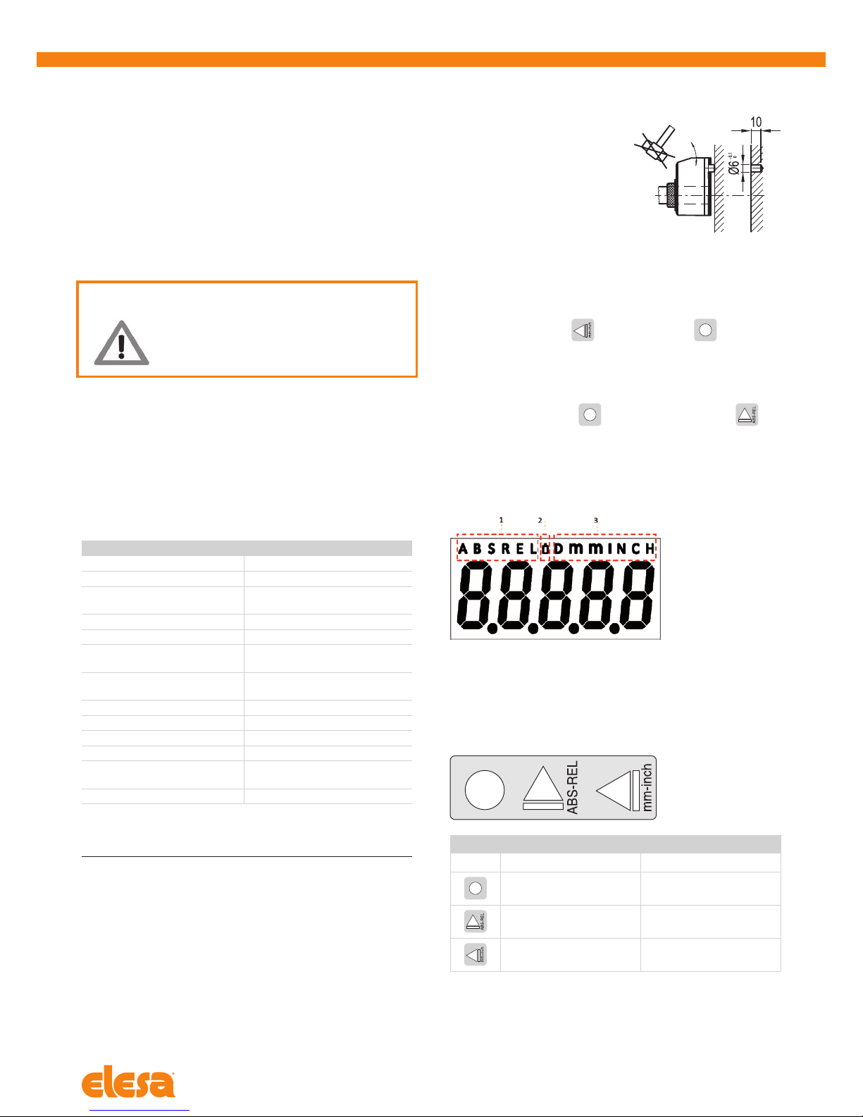
3. Assembly
1. Drill a Ø 6x10 mm hole in the body of the machine with a 22 mm centre
distance from the shaft to fit the
rear referring pin.
2. Fit the indicator onto the shaft and
make sure that the referring pin fits
into the hole.
3. Clamp the bushing to the shaft
by tightening the grub screw with
hexagon socket and cup end,
according to UNI 5929-85.
4. Turning on the system
After you have read and understood the section “Safety Instructions”, proceed
by switching on the indicator.
To turn the indicator on hold
while pressing the key .
The display will light up and the indicator will be ready to be used.
4.1 Turning off the system (only for storage)
To turn the system off enter the programming mode, select the
rESEt
parameter then press the key
. At this point, press the button for 5
seconds; the display will turn off and the indicator will go into low power mode
of the battery.
5. Symbols on the display
1. Absolute / incremental mode
2. Battery
3. Unit of measure (mm/inch/degrees)
6. Key function
FUNCTION
KEY Operating mode Programming mode
Access to the
programming mode
Parameter selection /
Confirm of parameter change
Absolute or
incremental mode selection
Digit increase /
programming mode exit
Unit of measure selection
Scroll for parameters /
digit selection
 Loading...