

Page 1
elero GmbH
Antriebstechnik
Linsenhofer Str.59–63
D-72660 Beuren
[email protected]
www.elero.com
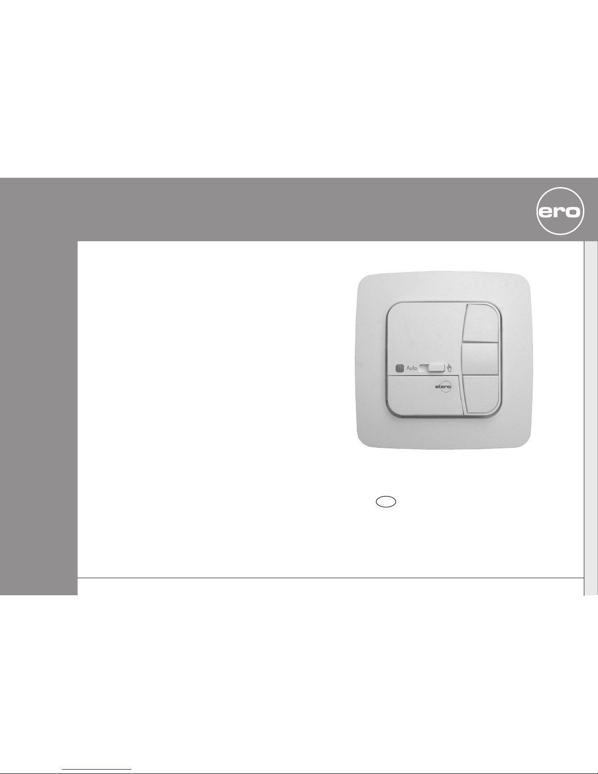
VarioTec
Nr. 18100.3401/0204309023
Operating instructions
Please keep these instructions in a safe place!
GB
elero
Page 2
Safety instructions
GB-2
Important safety instructions!
Always observe the following instructions.
Risk of injury by electric shock.
• All terminal connections to a 230 V network
must be made by an authorised electrician.
• Before assembly, always disconnect the mains
lead from the power supply.
• The provisions of the local public utilities and
stipulations for wet and damp rooms in
accordance with VDE 100 must be observed
during system installation.
• For use in dry rooms only.
• Use unmodified elero original parts only.
• Keep persons away from the systems guide
track.
• Keep children away from controls.
• Always comply with national stipulations.
• If the system is controlled by one or more
devices, the system guide track must be visible
during operation.
• Only cables with sufficient electric strength
may be used to connect control cables
(protective low voltages).
• The equipment contains small parts that could
be swallowed.
GB
Warning!
Safety instructions......................................... GB- 2
Explanation of displays and buttons ..................... GB- 3
General information ....................................... GB- 4
Designated use............................................. GB- 4
Installation/Connection VarioTec ......................... GB- 5
Connection as a drive controller...................... GB- 5
Connection as a group controller..................... GB- 6
Factory settings ............................................ GB- 7
Explanation of functions
Manual/Automatic sliding switch,
Alarm signal control light............................. GB- 7
Buttons ................................................. GB-8
Group control .......................................... GB- 8
Intermediate position,Ventilation/reverse position GB- 8
Drive controller, Group controller..................... GB-9
Selecting roller shutter/awning or venetian blind
mode.................................................... GB- 9
Function menu ............................................. GB- 9
Manual operation functions .......................... GB- 9
Automatic operation functions....................... GB-9
Programming menu........................................ GB-10
Programming intermediate position................. GB-10
Programming ventilation/reverse position .......... GB-10
Adjustment to intermediate position ................ GB-11
Adjustment to ventilation position................... GB-11
Adjustment to reverse position....................... GB-11
Deleting intermediate position....................... GB-11
Deleting ventilation/reverse position ................ GB-11
Technical data.............................................. GB-12
Cleaning .................................................... GB-12
Troubleshooting............................................ GB-12
General declaration of conformity........................ GB-12
Contents
GB-1
Page 3
General information/Designated use
GB-4
General information
The VarioTec device operates your roller shutters/ sun
protection systems on the basis of manual or external control
commands.
The VarioTec device can be operated manually at all times.
The VarioTec is characterised by its user-friendly operation.
Designated use
The VarioTec may be used to operate roller shutters/ sun
protection systems only.
This device may only be used in connection with equipment
from other manufacturers following consultation with your
local retailer.
GB
Explanation of displays and buttons
GB-3
VarioTec
Pos
Pos
Reset
POS button
POS button
Reset button
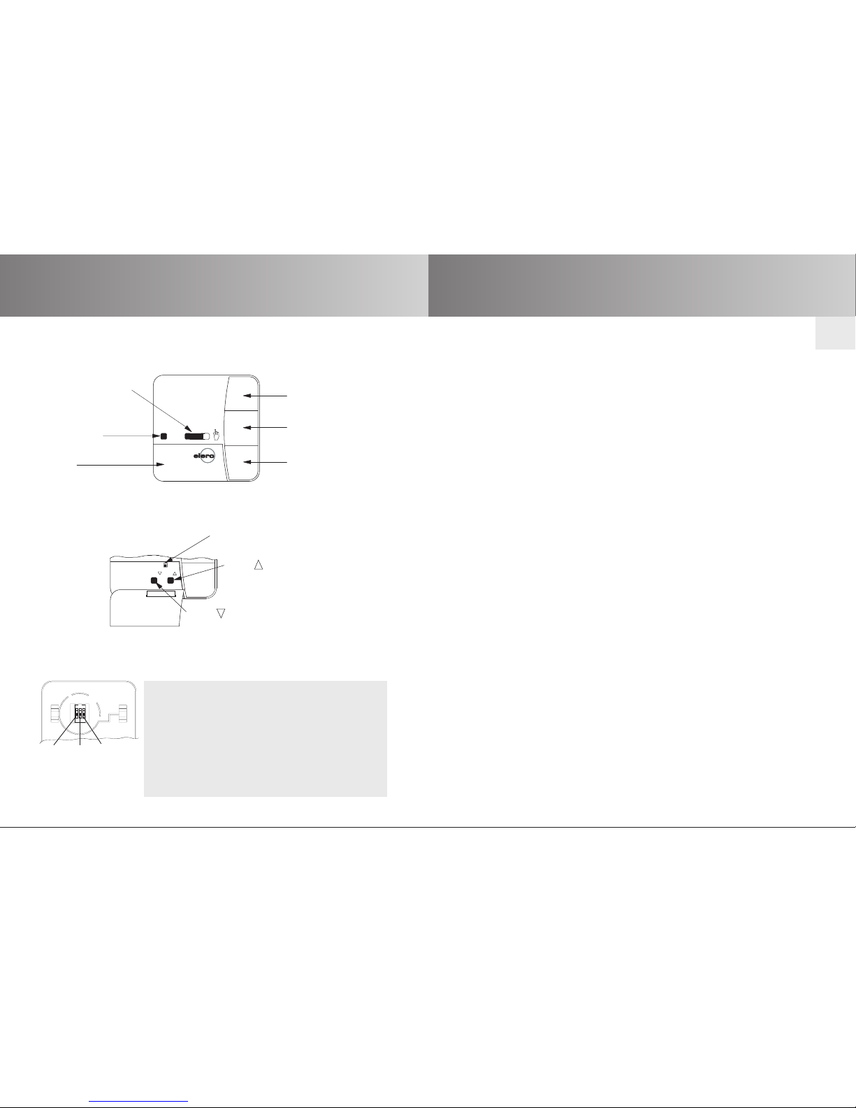
Explanation of displays
Buttons under the cover
Encoding switch (located on back of device)
Auto
DOWN button
STOP button
UP button
Alarm signal
control light
Cover
Manual/Automatic
sliding switch
1 Upper position W Alarm signal function OFF.
Lower position W Alarm signal function ON.
2 Upper position W Group controller
Lower position W Driver controller
3 Upper position W Venetian blind mode
Lower position W Roller shutter /
awning mode
On
On
1
2
3
Page 4
Installation
GB-6
GB
Installation/Connection
GB-5
Installation
To other
control devices
Individual
VarioTec
pushbutton
Venetian blind
21
N L
64 53
Central
C
1~
M
N
L
Mains
PE
230 V/50 Hz
Warning!
Risk of injury by electric shock!
• Terminal connections must be carried out by an
authorised electrician!
• If more than one drive is operated using the VarioTec,
the drives must be decoupled by relay controls.
• The switched current of the device must be observed
at all times!
To other
control devices
Individual
VarioTec
pushbutton
Venetian blind
21
N L
64 53
Central
C
N
L
Mains
230 V/50 Hz
Output
Input
To other
control devices
Warning!
Risk of injury by electric shock!
• Terminal connections must be carried out by an
authorised electrician!
3. Replace the protective caps on the power supply unit.
4.Secure the power supply unit in the box..
5. Insert the operating device into the frame and plug it into
the power supply unit..
3. Replace the protective caps on the power supply unit.
4. Secure the power supply unit in the box.
5. Insert the operating device into the frame and plug it into
the power supply unit.
Note:
Always use a shielded
control wire . . .0.8 mm
or JY-ST telephone line
...0.6 mm.
1. Remove the protective caps.
2. Connect.
Note:
Always use a shielded
control wire . . .0.8 mm
or JY-ST telephone line
...0.6 mm.
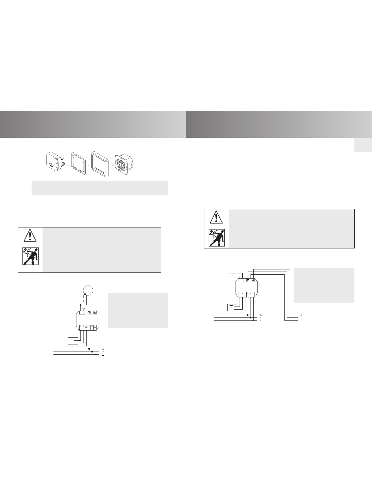
Connection as a drive controller
For details on suitable control systems,please refer to the control
product catalogue.
Note: The encoding switch located on the back of the VarioTec
device can be used to select group or drive control.
Connection as a group controller
For details on suitable control systems,please refer to the control
product catalogue.
1. Remove the protective caps.
2. Connect.
Page 5
Explanation of functions
GB-8
Reset button:
Press the Reset button (with a ballpoint pen or similar object) to
delete the intermediate position and the ventilation/reverse
position.
POS B:
The Pos B button can be used to programme an intermediate position.
POS V:
The Pos V button can be used to programme a ventilation/reverse
position.
Group control:
Group control refers to the simultaneous operation of several drives.
Intermediate position:
The intermediate position lies between the upper and lower limits
of the roller shutters/ sun protection system and can be freely
selected. The roller shutters/sun protection system can be moved
into this position from the upper end limit after programming.
To do so, press the DOWN button twice in quick succession.
When the system is in venetian blind mode, it is also possible to
programme a reverse position.In this case, this command will be
automatically executed following the intermediate position
command.
Ventilation/reverse:
The ventilation/reverse position lies between the upper and lower
limits of the roller shutters/ sun protection system and can be freely selected. Your roller shutters can be moved into this position
from the lower end limit until the ventilation slats are open.
In venetian blind mode, the blind slats are turned.
To do so, press the UP button twice in quick succession.
GB
Explanation of functions
GB-7
Explanation of functions
Manual/Automatic sliding switch
In the “MANUAL “ mode, only manual control commands and
alarm signals are executed (e.g.: by pressing UP, STOP, DOWN
buttons and alarm button).
When the sliding switch is set to “AUTO”, automatic control
commands are carried out (e.g. control signals via group control
inputs.).
Alarm signal control light
An alarm signal is a continuous switching signal at the group or
individual control inputs which lasts for more than 5 seconds.
If the alarm signal control light is illuminated, this indicates an
alarm signal. The encoding switch 1 can be used to switch the alarm
signal function on or off.
Factory settings
Encoding switch factory setting
1. Lower position Alarm signal function ON.
2. Lower position Driver controller.
3. Lower position Roller shutter / awning mode.
Page 6
Programming menu
GB-10
GB
Function menu/Explanation of functions
GB-9
Drive controller:
If the VarioTec device is being used as a drive controller, the drive
is directly connected to the VarioTec device, in which case external
signals are converted into control commands. Encoding switch 2
must be set to the lower position
.
Group controller:
If the VarioTec device is being used as a group controller,
additional group and drive control devices can be connected.
Encoding switch 2 must be set to the upper position.
Selecting roller shutter/awning or venetian blind:
Encoding switch 3 is used to select roller shutter/awning mode
(lower position) or venetian blind mode.
In venetian blind mode, the blind moves in non-maintained
command mode to ensure that the slats are positioned accurately.
Press and hold any control button for more than 1 second to
operate the venetian blind in maintained command mode.
Functions
Manual operation functions
• UP, STOP, DOWN
• Adjustment to intermediate position
• Adjustment to ventilation/reverse position
• Alarm signals
Automatic operation functions
In automatic mode, both manual and external control commands
are executed:
• External automatic control commands
• UP, STOP, DOWN
• Adjustment to intermediate position
• Adjustment to ventilation/reverse position
• Alarm signals
Programming
Programming the intermediate position
Prerequisite: The shutter/curtain/blind is in the upper end
limit position.
1. Press and hold the Pos B programming button.
2. Keeping this button pressed, then press the DOWN button
until the desired intermediate position has been reached.
Use the UP or DOWN button to make any necessary
adjustments.
3. Release the Pos B the programming button.The
intermediate position is now stored.
The control light will flash 3 times briefly.
Programming the ventilation/reverse position
Prerequisite: The shutter/curtain/blind is in the lower end
limit position.
1. Press and hold the Pos V programming button.
2. Keeping this button pressed, then press the UP button until
the desired ventilation/reverse position has been reached.
Use the UP or DOWN button to make any necessary
adjustments.
3. Release the Pos V programming button.The ventilation/
reverse position is now stored.
The control light will flash 3 times briefly
Page 7
Technical data/Cleaning/
Troubleshooting
GB-12
Programming
GB-11
Adjustment to intermediate position
The shutter/curtain/blind can only be moved into the
intermediate position from the upper end limit position.
1. Press the DOWN button twice in quick succession.
The shutter/curtain/blind is adjusted into the stored
intermediate position.
Adjustment to ventilation position (roller shutters)
Roller shutters can only be moved into the ventilation position
from the lower end limit position.
1. Press the UP button twice in quick succession.The shutters are
adjusted into the stored ventilation position.
Adjustment to reverse position (venetian blinds)
The venetian blind slats must be closed before the blind can be
adjusted into the reverse position.
1. Press UP button twice in quick succession.
The venetian blind is adjusted into the stored reverse position.
When the blind reaches the stored intermediate position the blind
slats are turned automatically (provided a reverse position has
been pre-programmed).
Deleting intermediate position
1. Press and hold the Pos B programming button for more than
5 seconds.The intermediate position is now deleted.
The control light will flash 3 times briefly.
Deleting ventilation/reverse position
Press and hold the Pos V programming button for more than
5 seconds.The ventilation/reverse position is now deleted.
The control light will flash 3 times briefly.
GB
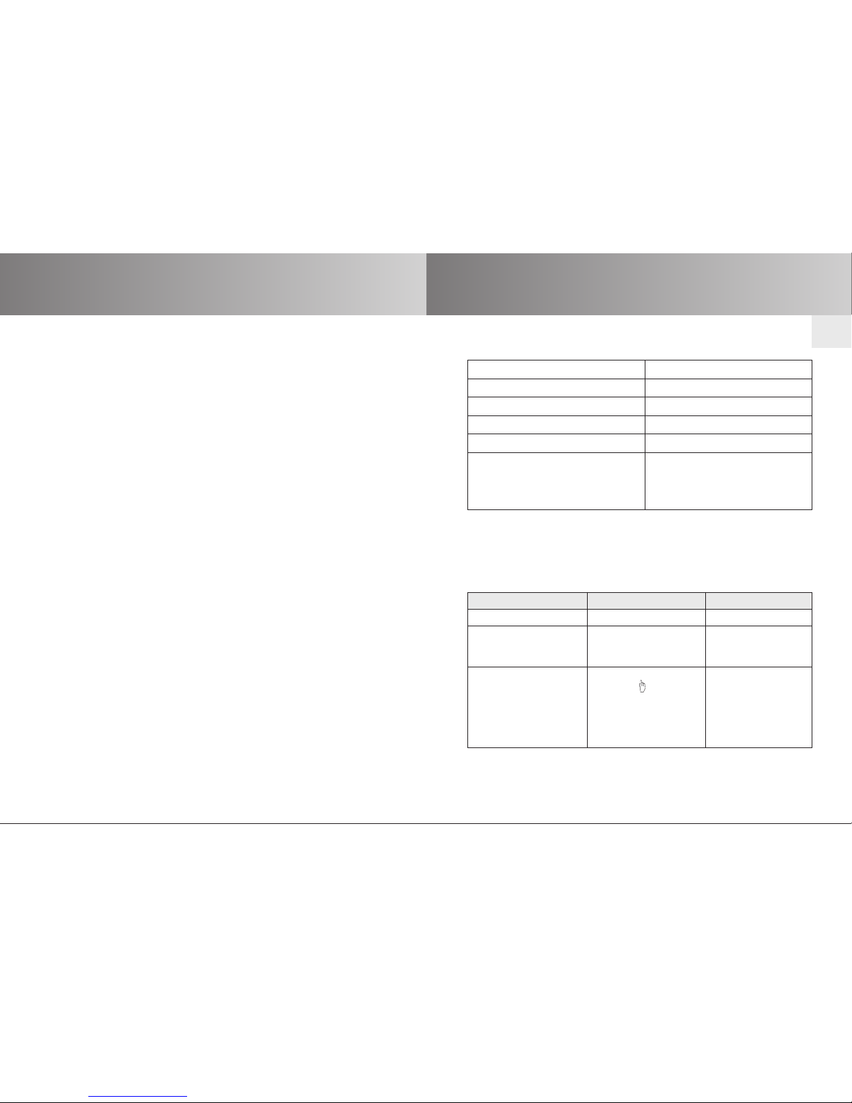
Nominal voltage 230-240 V AC / 50-60 Hz
Switched current 5 A /250 V AC for cos j = 1
System of protection IP 20
Protection class II
Permissible ambient temperature 0 to +55 °C
Type of installation Concealed: l 58 mm wall-
mounted
Exposed: in appropriate
exposed casing
Technical data
Cleaning
Clean the device with a damp cloth only.Do not use a cleansing
agent as doing so may damage the plastic.
Troubleshooting
Problem Cause Remedy
Drive is not functioning. Faulty connection. Check connection.
Drive moves in the Faulty connection. Exchange V and B
wrong direction. wires in the power
supply unit.
VarioTec does not 1. Device is set to 1. Set the device to
carry out external manual mode. automatic mode.
control commands. 2. Alarm signal is active. 2.Wait until alarm
signal disappears
or rectify problem
causing signal.
General declaration of conformity:
The company elero GmbH hereby declares that the VarioTec device
complies with the basic requirements and other relevant regulations
of the EC Directive 1999/5/EG.
Page 8
Warnhinweise
GB-14GB-13
GB
 Loading...