

elero JA Comfort series, JA 06 comfort, JA 09 comfort, JA 04/35 comfort, JA 06/35 comfort User Manual
...Page 1
Venetian Blind Drive JA Comfort
168030001_EN_0219
Application/special features/scope
of delivery/accessories
Application:
• Electronic drive for indoor/outdoor venetian blinds
• Suitable for head rails as of 51 x 57 mm (height x width)
Special features:
• Drive on both sides with silent soft brake
• Limit stop: electronic
• Slow travel during rotation of slats
• Standstill detection of drive shaft
• Soft start (2 speeds: slow/fast)
• The travel directions OPEN and DOWN/CLOSED are
permanently assigned.
Important:
Observe the direction of the movement symbol on the
cable side on the drive
• Safety cut-out limit switch: Optional as a reference point
for band length compensation by means of cyclical
reference runs
Standard scope of delivery:
• Drive with 0.8 m connecting cable with Hirschmann
plug STAS3, assembly kit, safety instructions and
assembly instructions
Accessories:
• Deector for connecting cable, blind clamping set,
clips, damper systems, Quick Snap shaft couplings,
mushroom button extension (cut-out extension)
• Hirschmann couplings, control units
Safety instructions
Important safety instructions Observe all assembly instructions. Incorrect assembly can lead to serious injuries.
General safety instructions for use, including installation of
venetian blind drives, can be found in the "Safety instruc-
tions" leaet supplied with each drive. Please read these
assembly instructions carefully as the procedure in this
manual is a prerequisite for correct use of the product.
Figures included are for illustration purposes only. The
illustrations may dier from your product on minor details
and are provided for general information only.
elero GmbH continuously strives to improve all products.
As a result, the specications, features and technology of
this product may be changed at any time. The information
provided is based on current information at the time of pub-
lication. Do not perform any modications to the device.
No claims can be derived from the technical data, images
and information provided in this manual.
Additional assembly instructions:
• Before installing the drive, all lines and equipment which
are not required for operation must be deactivated.
• The rated torque and rated operating time must be
suitable for the properties of the driven part (the blind).
:$51,1*
Risk of injuries due to hot surfaces. The drive
will heat up during operation, the drive casing
can become hot. Skin burns are possible.
• Wear personal protection equipment (protective gloves).
• Venetian blind drives that are installed below 2.5 m
above the oor or at another level that allows access to
the drive must be installed so that direct contact of the
drive or other components that heat up during operation
is precluded e.g. by installing a cover.
&$87,21
Assembly
The drive is intended exclusively for right hand installation
with its lower end position preset. Right-hand installation
refers to the view from the outside of the building looking
in, cable outlet and front with marking (direction of movement symbol) are located on the right.
Mounting the safety cut-out
On the underside of the limit switch housing, insert the safety cut-out into the openings and clip it in. Check the safety
cut-out is working. Any malfunctions may lead to damage.
If the safety cut-out is not long enough, it can be extended
by 10 mm at a time with the safety cut-out extension
(Accessories, article number 161014501) (attach max.
3 cut-out extensions).
Insert a small at screwdriver into one of the notches on
the orange cover and apply pressure to the blade towards
the middle of the mushroom button, levering o the cover.
Clip on the extension and then clip on the cover again.
Mounting the optional mushroom button extension
• Use the extended version of the mushroom button
(accessories) instead of the original mushroom button.
Clip this in/out to replace it.
Mounting of QuickSnap coupling
1. Attach the coupling on the drive shaft so it is diagonal.
When doing so, pay attention to the position of coupling
and shaft. The retaining springs must slide on the
top surface.
2. Push on the coupling until the retaining spring audibly
latches in the notch. Hold the drive shaft steady by
pushing against it at the other end.
3. Jerk the coupling to check whether it is held securely.
Dismantling the QuickSnap coupling
• Lift the retaining spring on the coupling using a suitable
screwdriver and pull o the coupling.
Installation in venetian blind head rail
Note: Select the damper system according to the specied
shaft height (see Accessories).
1. Attach the damper on the drive or the head rail. Install
the drive without pressure into the head rail so it is
positioned correctly (mushroom button pointing down).
Do not knock the drive, shaft or coupling. Do not load
the drive shaft in radial direction.
2. Note: Secure the drive from turning in the head rail
using the countersunk screws and the optional clips.
3. Insert the venetian blind shafts into the QuickSnap
couplings so they are in the correct position and secure
them to prevent them from sliding out.
127,&(
Electrical connection
All electrical work may only be carried out by authorised
electricians according to the applicable rules and regulations of the trade association and the requirements laid
out in DIN VDE 0100. Furthermore, the national legal regulations applicable in the respective country of use must
be observed. Connect the electrical connection only when
the power is turned o. To do so, disconnect the mains
supply cable from the power supply and secure it. Persons
failing to observe the requirements may be held liable for
damage to property and personal injuries.
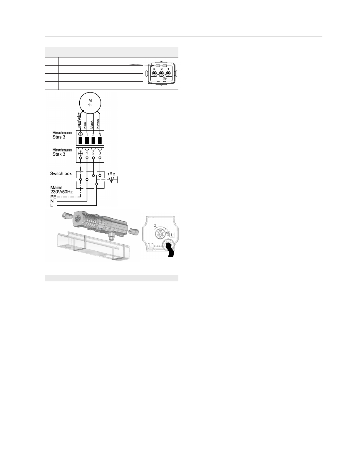
Connect according to the following scheme while observing
the following notes:
• Min. switchover delay 500 ms (voltage-free) in case of
a change in direction of rotation due to locked push
buttons/switches/control units.
• Parallel switching of several JA type drives is possible.
• Please note the maximum switching capacity of the
control unit.
After installation of the venetian blind, attach
these instructions to the connecting cable for
the electrician.
Page 2
2 | EN © elero GmbH
Adjusting the end positions and turning range
Plug drive cable assignment
PE Yellow/green protective conductor
N ① Neutral conductor/blue
L1 ② Phase/black OPEN
L2 ③ Phase/brown DOWN/CLOSE
On initial commissioning, the drive is in delivery condition:
Lower end position has been reached. Upper end position
needs to be set (see Setting upper end position).
The end positions and turning range of the slats are set with
the elero assembly cable.
Connection for elero assembly cable
• Drive is powered via “OPEN” or “DOWN/CLOSE” via one
of the cables a), b) or c)
a) Assembly cable 23 395.7702:
Operation with Hirschmann coupling Stas 3 (without
adapter cable and connection terminal in box) and
rotary switch in right position.
b) Assembly cable 23 243.0002 with connection terminal
c) Assembly cable 23 246.0001 with Hirschmann
coupling
• Setting the end postions and turning range:
see “Setting the end positions and turning range”
• If, after travel, “OPEN” and “DOWN/CLOSE” are pressed
simultaneously, setting the end positions starts and the
transmitter operation commences. After 9 seconds or
after pressing the hand-held transmitter, setting the end
positions is cancelled.
Adjusting the end positions and turning range
Turning range of slats
• This is the range of movement in which the position
of the slats is set at low speed. The standard setting
is 270° based on the drive shaft.
• This can optionally be changed upon setting the lower
end position, at minimum 90° (rst OPEN movement plus
1 increment), maximum 360°.
Setting end positions
Generally speaking, only one end position (top or bottom)
can be reset; this leads to a deletion of the previous setting.
• If both the top and the bottom end position are to be set,
the procedure needs to be carried out twice accordingly.
• On initial commissioning (lower end position reached,
drive is in the setting mode for upper end position), skip
point 1 below and continue at point 2 depending on the
upper limit stop required later on.
1. With the elero assembly cable connected and in middle
blind position, press the buttons OPEN and DOWN/
CLOSED simultaneously and hold them down until the
drive initiates brief upward and downward motion.
Freely conguring the upper end position without
inuence of the mushroom button
2.Press the OPEN buttonuntil the desired position is reached
(drive starts up, stops briey and continues).
3. Corrections are possible in inching mode using the OPEN
and DOWN/CLOSE buttons. If the DOWN/CLOSE button
is pressed down permanently, this position will be stored.
4. Press the DOWN/CLOSED button until the drive
stops automatically.
The upper end position has been freely configured. Even if a
mushroom button is present, no reference runs will be made.
5. Remove the assembly cable, connect the electrics, check
assignment of the travel directions.
Setting upper end position on the mushroom button
2. Press the OPEN push button until the drive is stopped
by the mushroom button (drive starts up, stops briey
and continues).
Upper end position is set and is at the position of the
mushroom button. No reference runs are performed.
3. Remove the assembly cable, connect the electrics, check
assignment of the travel directions.
Adjust the upper end position to the cover position *)
(with cyclical reference runs)
*) Cover position: 3 turns of the drive shaft below the
mushroom button at maximum
2. Press the OPEN push button until the drive is stopped
by the mushroom button (drive starts up, stops briey
and continues).
3. Press and hold down the OPEN button and the DOWN/
CLOSE button too until the desired position is reached.
Release both buttons.
Upper end position is set and is located at the position
in front of the mushroom button. Cyclical reference runs
are performed.
4. Remove the assembly cable, connect the electrics, check
assignment of the travel directions.
Setting the lower end position and the turning range
to standard
2. Press the DOWN/CLOSE button until the desired position
is reached (drive starts up, stops briey and continues).
3. Corrections are possible in inching mode using the OPEN
and DOWN/CLOSE buttons.
4. Press the OPEN button until the drive stops automatically.
The lower end position has been set. The turning range is
set to 270° (standard).
5. Remove the assembly cable, make an electrical
connection, check assignment of the travel directions.
Page 3
© elero GmbH EN | 3
Technical data and dimensions
EU Declaration of Conformity
This product conforms to basic requirements and all other
pertinent provisions in EU Directives. For the full declaration
of conformity, see www.elero.com/downloads-service/
Manufacturer's
address
Service
elero GmbH
73278 Schlierbach
GERMANY
www.elero.de
If malfunctions have occurred or
the device has been damaged
despite proper handling, please
contact your contractor or dealer.
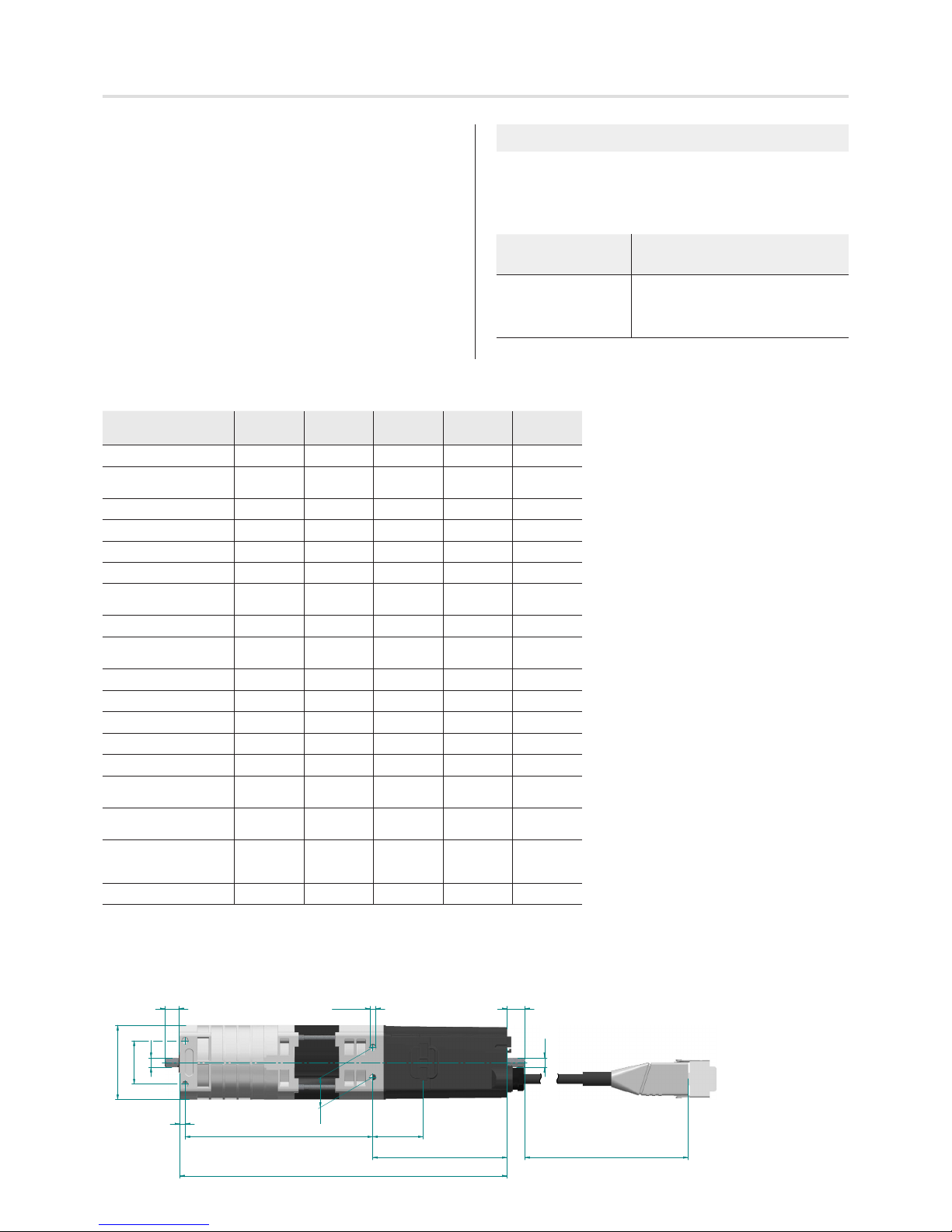
Technical data JA 06
comfort
JA 09
comfort
JA 04/35
comfort
JA 06/35
comfort
JA 04/50
comfort
Rated torque [Nm] 6 9 4 6 4
Rated speed |
Slow travel [rpm]
26 | 6 26 | 6 35 | 6 35 | 6 50 | 6
Rated voltage [V] 1 ~ 230 1 ~ 230 1 ~ 230 1 ~ 230 1 ~ 230
Rated frequency [Hz] 50 50 50 50 50
Noiseless soft brake
✓ ✓ ✓ ✓ ✓
Rated current [A] 0.50 0.68 0.50 0.68 0.68
Rated power consumption [W]
115 156 115 156 156
Protection class I
✓ ✓ ✓ ✓ ✓
Limit switch range
(revolutions)
100 100 100 100 100
Protection class (IP) 54 54 54 54 54
Operating time (min S2) 5 4 5 4 4
Length "a" [mm] 139 154 139 154 154
Length "b" [mm] 243 258 243 258 258
Weight [kg] 1.60 1.95 1.60 1.95 1.95
Ambient operating
temperature [°C]
-20 ... 60 -20 ... 60 -20 ... 60 -20 ... 60 -20 ... 60
Standby energy eciency [W]
< 0.3 < 0.3 < 0.3 < 0.3 < 0.3
Connecting cable [m]
with Hirschmann-plug
Stas 3 and clip
0.8 0.8 0.8 0.8 0.8
Item number 352210001 352310001 352250001 352350001 352450001
10,2
7SW
37,5
100 800
"b"
M5 9tief (8x) 10,6
7SW
22
"a"
4
32
55 x55
Freely conguring the lower end position and the
turning range (minimum 90° to maximum 360°)
2. Press the DOWN/CLOSE button until the desired position
is reached (drive starts up, stops briey and continues).
3. Corrections are possible in inching mode using the OPEN
and DOWN/CLOSE buttons.
4. Press and hold down the OPEN button until the desired
turning range is reached (slats open slightly to begin
with and continue opening further in small increments
after 2 seconds).
Corrections to the turning range in down/closed direction
are not possible. Releasing the OPEN push button will
save the turning range.
The lower end position has been set. The turning range is set.
5. Remove the assembly cable, make an electrical
connection, check assignment of the travel directions.
Page 4

Notes
We reserve the right to make technical changes
elero GmbH
Antriebstechnik
Maybachstr. 30
73278 Schlierbach
[email protected]
www.elero.com
 Loading...