

Eleris EM303B User Manual

User Manual
EM303B General Purpose Inverter
1
Preface
Thank you for purchasing EM303B series inverter.
Document No.: 31010032
Version No.:104
Issue Date: 11/2015
EM303B is a general purpose vector control inverter. An induction motor with the help of
EM303B canpossess fast speed response and torque control ability as a DC motor which
makes the motion control system stable, precise,and quick.
Main Features:
1. SVC (Sensorless vector control):Torque control accuracy: 5% rated torque. Speed
control accuracy: ±0.2% rated synchronous speed.
2. VVF (Vector decoupling based VF control): The steady performanceis the same as that
in SVC.
3. Wide speed regulation range, load capacity at low frequency: SVC/0.5Hz/150% rated
load, VVF/1.0Hz/150% rated load.
4. Optimized current and voltage protection algorithm ensures that motor can
accelerate/deceleratein 0.1S.
5. AVR function makes output voltage stable at grid voltage fluctuation.
6. Load disturbance compensation ensures failure-free operation of motor.
7. Auto-searching motor speed at restart smoothes thestart of motor without current
over-shoot.
8. 2 acceleration/deceleration modes: linear and S curve.
9. The performance and stability are improved significantly with dual- CPU.
It is the duty of any user to perform the appropriate, correct installation or configuration of
the optional parameters of the devices. Neither SINEE nor its distributors shall be responsible
or liable for misuse of the information contained herein or mismatching the inverter with the
motor.
In the interests of commitment to a policy of continuous development and improvement,
SINEE reserves the right to update the specification of the product or its performance, or the
content herein without notice.
www.eleris.ru

User Manual
EM303B General Purpose Inverter
2
Contents
PREFACE ............................................................. 1
CONTENTS ............................................................ 2
SAFETY INFORMATION ................................................. 4
SAFETY PRECAUTIONS ..................................................... 4
1OVERVIEW ........................................................... 8
1.1 EM303B MODEL LIST AND TECHNICAL SPECIFICATIONS ......................... 8
1.2 DEFINITION OF EM303B OPERATION STATUS ................................ 10
1.3 EM303B OUTLOOK ................................................... 13
2INSTALLATION ...................................................... 14
2.1 VERIFYING PRODUCT .................................................. 14
2.2 OVERALL AND INSTALLATION DIMENSIONS .................................. 15
2.3 CONSIDERATIONS OF INSTALLATION SITE .................................... 17
2.4 DIRECTION AND SPACE OF INSTALLATION ................................... 17
2.5 DISASSEMBLY AND ASSEMBLY OF KEYPAD .................................. 19
2.6 FLUSH MOUNTING .................................................... 21
3WIRING ............................................................. 22
3.1 CONNECTIONS TO PERIPHERALS .......................................... 22
3.2 WIRING MAIN CIRCUIT TERMINALS ....................................... 23
3.3 WIRING CONTROL CIRCUIT TERMINALS .................................... 31
3.4 EXTENDING KEYPAD WIRE .............................................. 39
3.5 WIRING CHECK ....................................................... 40
4KEYPAD OPERATION ................................................. 41
4.1 TYPE AND FUNCTION OF KEYPAD ......................................... 41
4.2 LED KEYPAD OPERATION MODE ......................................... 42
5TRIAL OPERATION ................................................... 49
5.1 TRIAL OPERATION PROCEDURES .......................................... 49
5.2 TRIAL OPERATION PRECAUTIONS ......................................... 50
6PARAMETER TABLE .................................................. 52
6.1 FORMAT OF PARAMETER TABLES .......................................... 52
6.2 PARAMETER TABLE .................................................... 52
SECTION 1 GENERAL PARAMETERS ........................................... 52
SECTION 2 ADVANCED PARAMETERS .......................................... 66
7PARAMETER DESCRIPTION ........................................... 81
SECTION 1 GENERAL PARAMETERS ........................................... 81
7.1 F0 GROUP: GENERAL PARAMETERS ........................................ 81
7.2 F1 GROUP: MOTOR PARAMETERS ......................................... 92
7.3 F2 GROUP: INPUT/OUTPUT TERMINAL PARAMETERS ........................... 95
7.4 F3 GROUP: PRESET SPEED OPERATION PARAMETERS .......................... 105
7.5 F4 GROUP: GENERAL PARAMETERS OF PID ................................. 110
7.6 F5 GROUP: GENERAL PARAMETERS OF VECTOR CONTROL ...................... 116
7.7 C0 GROUP: PARAMETERS OF MONITORING FUNCTION ......................... 121
www.eleris.ru

User Manual
EM303B General Purpose Inverter
3
SECTION 2 ADVANCED PARAMETERS ......................................... 122
7.8 F6 GROUP: SIMPLE PLC FUNCTION ....................................... 122
7.9 F7 GROUP: ADVANCED PARAMETERS OF OPERATION .......................... 128
7.10 F8 GROUP: INPUT/OUTPUT BIAS ........................................ 133
7.11 F9 GROUP: SPEED SETTING OPTIONS ..................................... 137
7.12 FA GROUP: ADVANCED PARAMETERS OF VECTOR CONTROL ................... 145
7.13 FC GROUP: PARAMETERS OF OPERATION CONTROL .......................... 146
7.14 FD GROUP: AUXILIARY PARAMETERS .................................... 155
7.15 FE GROUP: USER DEFINED TERMINAL FUNCTION PARAMETERS ................ 158
8AUTOTUNING MOTOR PARAMETERS ................................. 162
8.1 AUTOTUNING MOTOR PARAMETERS ...................................... 162
8.2 PRECAUTIONS BEFORE AUTOTUNING ..................................... 162
8.3 AUTOTUNING PROCEDURE ............................................. 163
9TROUBLESHOOTING ................................................ 164
9.1 FAULTS ............................................................ 164
REFERENCE OF LED CHARACTERS .......................................... 166
9.2 FAULT ANALYSIS ..................................................... 167
10MAINTENANCE AND INSPECTION ................................... 170
10.1 MAINTENANCE AND INSPECTION ........................................ 170
10.2 DAILY INSPECTION .................................................. 170
10.3 PERIODIC MAINTENANCE ............................................. 170
10.4 PERIODIC MAINTENANCE AND REPLACEMENT OF PARTS ...................... 171
10.5 OUTLINE OF WARRANTY .............................................. 171
11ACCESSORIES ..................................................... 172
11.1 KEYPAD EXTENSION WIRE ............................................ 172
11.2 REMOTE CONTROL CASE .............................................. 172
11.3 BRAKING RESISTOR ................................................. 173
11.4 BRAKING UNIT ..................................................... 174
11.5 CONNECTING CABLE ................................................. 174
11.6 CHASSIS FOR FLOOR MOUNTING ........................................ 174
11.7 EXTENDED COPPER BAR .............................................. 176
12MODBUS COMMUNICATION PROTOCOL .............................. 177
12.1 APPLICATION SCOPE ................................................. 177
12.2 PHYSICAL INTERFACE ................................................ 177
12.3 PROTOCOL FORMAT ................................................. 177
12.4 EXPLANATION OF COMMAND .......................................... 177
12.5 DESCRIPTION OF PROTOCOL FORMAT .................................... 179
12.6 DESCRIPTION OF CONTROL COMMAND ................................... 182
12.7 EXAMPLE ......................................................... 183
12.8 TROUBLESHOOTING OF COMMON COMMUNICATION .......................... 184
www.eleris.ru
User Manual
EM303B General Purpose Inverter
4
Safety Information
Danger: The addition of this symbol to a Danger or Warning safety label
indicates that an electrical hazard exists, which will result in personal injury if
the instructions are not followed.
Caution: This is the safety alert symbol. It is used to alert you to potential
personal injury hazards. Obey all safety messages that follow this symbol
to avoid possible injury or a risk of damage to the products or other devices.
Safety Precautions
Before Installation
Danger
1. Do not install the product if the package is with water, or component is missing or
broken.
2. Do not install the product if the label on the package is not identical to that on the
inverter.
Danger
1. Be careful of carrying or transportation. Risk of devices damage.
2. Do not use damaged product or the inverters missing component. Risk of injury.
3. Do not touch the parts of control system with bare hands. Risk of ESD hazard.
Installation:
Danger
1. Installation base shall be metal or other non-flammable material. Risk of fire.
2. Do not unscrew the fixing bolts, especially the bolts with red mark.
Caution
1. Do not leave cable strips or screws in the inverter. Risk of inverter damage.
2. Install the product at the place with less vibration and no direct sunlight.
3. Consider the installation space for cooling purpose when the inverter is installed in a
cabinet.
www.eleris.ru
User Manual
EM303B General Purpose Inverter
5
Wiring:
Danger
1. Wiring must be performed by authorized and qualified personnel. Risk of danger.
2. Circuit-breaker should be installed between inverter and the mains. Risk of fire.
3. Be sure that the power supply is off before wiring, and ground inverter as per standard
wiring. Risk of electrical hazard.
4. Grounding terminal must be grounded. Risk of electrical hazard and fire.
5. Dual keypad is not recommended. Risk of unexpected danger.
Caution
1. Never connect input power supply cable to output terminals U, V, and W of inverter. Pay
attention to the terminal symbols, connect them correctly. Risk of inverter damage.
2. Be sure that the wiring meets EMC requirements and local safety standard. Cables
should be in recommended sizes. Risk of accident.
3. Do not connect braking resistor to DC bus terminal & . Risk of fire.
4. Tighten terminals with screw drivers of specified torque. Risk of fire.
5. Do not connect phase-shifting capacitor and LC/RC noise filter to output circuits.
6. Do not connect the solenoid switch and electromagnetic contactor to output circuits.
Otherwise, it will trigger overcurrent protection, or damage inverter.
7. Do not disconnect internal wires of inverter. Risk of inverter damage.
Before Power-on
Caution
1. Verify that the input voltage is identical to the rated voltage of product, correct wiring of
input terminals R, S, and T and output terminals U, V, and W, wiring of inverter and its
peripheral circuits, and all wires should be in good connection. Risk of inverter damage.
2. Never perform voltage withstanding test on inverter, it has been done at ex-works. Risk
of accident.
Danger
1. Inverter shall be power-on only after the front cover is assembled. Risk of electrical
hazard.
2. Wiring of all peripherals should abide by the guide of this manual. Risk of accident.
www.eleris.ru
User Manual
EM303B General Purpose Inverter
6
After Power-on
Danger
1. Do not touch the inverter and its peripheral circuits with wet hands. Rick of electrical
hazard.
2. Do not touch any input/output terminals of inverter with bare hands. Rick of electrical
hazard.
3. After power is on at the first time, inverter will detect external circuit automatically.
Meanwhile, do not touch wiring terminals U, V, and W of inverter, or wiring terminal of
motor with bare hands. Rick of electrical hazard.
Danger
1. If autotuning is required, be careful of personal injury when motor is running. Risk of
accident.
2. Do not change the defaults of parameters. Risk of devices damage.
Trial Operation
Danger
1. Only after the front cover is installed, power can be turned on. Never take off the front
cover when power is on.
An electric shock may occur.
2. Do not come close to the machine at power failure if fault reset function is active. The
inverter will restart automatically when power is on.
An injury may occur.
3. Install an emergency switch for a quick brake in case of abnormal conditions. (
STOP
RESET
is
only enabled in keypad control mode.)
An injury may occur.
Caution
1. Never touch braking resistor. It will be very hot and with high-voltage when running.
Otherwise, an electric shock and a burn injury may occur.
2. Reconfirm the motor and machine are within the applicable ranges before starting
operation.
Otherwise, an injury may occur.
3. Do not check signals while the inverter is running.
Otherwise, the inverter will be damaged.
4. Be careful when editing inverter settings. The inverter is in factory default.
Otherwise, the inverter will be damaged.
User Manual
EM303B General Purpose Inverter
7
During Operation
Danger
1. Do not touch cooling fans, heat sink, metal panel, or discharge resistor with bare hands.
Risk of burning.
2. Non-professionals shall not detect signals during operation. Risk of personal injury or
device damage.
Caution
1. Prevent any foreign items from being left in the devices during operation. Risk of device
damage.
2. Do not control start/stop of inverter by ON/OFF of contactor. Risk of device damage.
Maintenance
Danger
1. Maintain and inspect devices after power is off. Risk of electric hazard.
2. Maintain and inspect inverter only after the voltage is lower than DC 36V between DC
bus terminals & , and power is off for 5 minutes. The residual charge on capacitor
may cause personal injury.
3. Maintenance and inspection can only be performed by professionals. Risk of personal
injury.
4. Parameter setting is required if inverter has been replaced. Plug-in& plug-out should be
performed after power-off.

User Manual
EM303B General Purpose Inverter
8
1 Overview
1.1 EM303B Model List and Technical Specifications
Rated voltage: 3-phase, 380VAC
Applicable motor: 3-phase induction motor, power range: 0.75~400kW.
Output voltage: 3-phase, from 0 to U
supply
.
1.1.1 EM303B Model and Rated Output Current
Table 1-1 Model List of EM303B
Rated Voltage
Model No.
Motor Power(kW)
Rated Output Current(A)
3-phase,
380VAC
±20%
EM303B-0R7G/1R1P-3B
0.75/1.1
2.8/3.7
EM303B-1R1G/1R5P-3B
1.1/1.5
3.7/4.8
EM303B-1R5G/2R2P-3B
1.5/2.2
4.8/6.2
EM303B-2R2G/3R0P-3B
2.2/3.0
6.2/8.0
EM303B-3R0G/4R0P-3B
3.0/4.0
8.0/10.0
EM303B-4R0G/5R5P-3B
4.0/5.5
10.0/13
EM303B-5R5G/7R5P-3B
5.5/7.5
13/17
EM303B-7R5G/9R0P-3B
7.5/9.0
17/20
EM303B-9R0G/011P-3B
9.0/11
20/26
EM303B-011G/015P-3B
11/15
26/34
EM303B-015G/018P-3B
15/18.5
34/41
EM303B-018G/022P-3
18.5/22
41/48
EM303B-022G/030P-3
22/30
48/60
EM303B-030G/037P-3
30/37
60/75
EM303B-037G/045P-3
37/45
75/90
EM303B-045G/055P-3
45/55
90/115
EM303B-055G/075P-3
55/75
115/150
EM303B-075G/090P-3
75/90
150/180
EM303B-090G/110P-3
90/110
180/220
EM303B-110G/132P-3
110/132
220/265
EM303B-132G/160P-3
132/160
265/310
EM303B-160G/185P-3
160/185
310/360
EM303B-185G/200P-3
185/200
360/380
EM303B-200G/220P-3
200/220
380/420
EM303B-220G/250P-3
220/250
420/470
EM303B-250G/280P-3
250/280
470/530
EM303B-280G/315P-3
280/315
530/600
EM303B-315G/355P-3
315/355
600/660
EM303B-355G/400P-3
355/400
660/740
EM303B-400G/450P-3
400/450
740/820
Remarks:
EM303B is an integrated model with G (fixed torque) and P (square torque) in one. The data
listed above is of Model G. When applied to square torque like blower, water pump and etc.,
the power ratings of applicable motor can be one grade higher. See inverter’s nameplate for
details.

User Manual
EM303B General Purpose Inverter
9
1.1.2 EM303B Technical Specifications
Table 1-2 EM303B Technical specifications
Items
Specifications
Input Rated Voltage
3-phase 380VAC±20%, 50~60Hz±5%,
voltage imbalance rate <3%
Output
Output Voltage
3-phase, from 0 to U
supply
.
Rated Output Current
100% rated current non-
stop output
Max. Overload Current
Model G: 150% rated current for 1 minutes, 180% rated
current for 10 seconds
Model P: 120% rated current for 1 minutes, 150% rated
current for 10 seconds
Basic
Control
Functions
Control Mode
V/F, SVC0, SVC1
Input Mode
Frequency (Speed) input, torque input
Start/Stop Control Mode
Keypad, control terminals (2-wire sequence, 3-wire
sequence), RS485
Frequency Control Range
0.00~600.00Hz
Input Frequency Resolution
Numeric input: 0.01Hz, analog input: 0.1% of maximum
frequency
Governor Deflection
1:50(V/F), 1:100(SVC)
Speed Control Accuracy
±0.2% rated synchronous speed
Acceleration/Deceleration Time
0.01~600.00 seconds/minutes
V/F Features
Rated output voltage: 20%~100% adjustable
Frequency base :20Hz~600Hz adjustable
Torque Boost
Automatic torque boost, fixed torque boost curve,
customer defined V/F curve scaling
Start Torque
150%/1Hz(V/F),150%/0.5Hz(SVC)
Torque Control Accuracy
±5% rated torque (SVC1)
AVR
AVR is active while output voltage remains unchanged if
input voltage is varying.
Automatic Current Limit
Automatically limit output current, avoid tripping
overcurrent
frequently
DC Brake
Brake frequency:0.1~60Hz, brake time:0~30S,
brake current:0~150% rated current
Signal Input Source
Communication, analog voltage, analog current, preset
speed, simple PLC and their combinations
Special
Function
Control
Textile Wobbulation
Achieve textile wobbulation functions like wobbulation
range, time and jump
Function of
Input and
Output
Reference Power Supply
10V/20mA
Terminal Control Power Supply
24V/150mA
Numeric Input Terminals
7 programmable numeric input terminals
Analog Input Terminals
4 analog inputs:2 voltage inputs (0~10V), and 2 current
inputs(0~20mA)
Numeric Output Terminals
2 OC outputs and 1 relay output are programmable.
Maximum output current of OC: 50mA. Relay contact
capacity: 250VAC/3A or 30VDC/1A. When relay acts,
EA-EC is on, and EB-EC is off.
Analog output Terminals
2 programmable analog output terminals can output 0~10V
or 0~20mA
Keypad
Display
LED
Human interactions with displays and control actuators
Parameter Copy
Upload and download parameter information of the
inverter, copy parameters rapidly.
Protections
Protections
Short circuit, overcurrent, overload, overvoltage,
undervoltage, phase loss, overheating, external fault, and
etc.
Application
Conditions
Installation Site
Indoor, with altitude less than 1000 meters, free from dust,
corrosive gas, and direct sunlight
Ambient Temperature
-10℃~+40℃. In the temperature range +40 °C…+50 °C,
the rated output current is decreased by 1% for every
additional 1 °C. 20%~90%RH (no condensation)
Vibration
<0.5g
Storage Temperature
-25℃~+65℃
Installation Method
Wall mounting, floor mounting, flush mounting
Degree of Protection
IP20
Cooling Method
Forced air cooling
www.eleris.ru

User Manual
EM303B General Purpose Inverter
10
1.2 Definition of EM303B Operation Status
1.2.1 Operation Status of Inverter
Parameters setting status
After power is on, inverter finishes initialization and enters standby status without fault
or start-up command. Meanwhile, it does not output.
Normal running status
After receiving active start command through keypad, control terminal or RS485, the
inverter drives motor in accordance with the requirements of setting input.
JOG running status
Set by keypad, external terminal or RS485 to make motor run as per JOG input speed.
JOG stop status
Refer to the process that the output frequency drops to zero in JOG deceleration time
after JOG running command is not active.
Autotuning status
Set by keypad to autotune motor’s parameters in stationary or rotational autotuning.
Stop status
Refer to the process that the output frequency drops to zero in given deceleration time
after running command is not active.
Fault status
Status of inverter at protections, all kinds of faults and failures.
1.2.2 Control Modes of Inverter
The control modes of inverter refer to that the inverter controls motor rotation as per required
speed and torque with open loop or close-loop control mode. The control modes include:
General open loop space vector control——V/F control
Applicable to the applications of low speed changes and low speed stability accuracy
demand, and meet needs of most of AC motor drives.
SVC 0—— Open-loop vector control without PG feedback
Only estimate speed in real-time, but no feedback control. Output current is under
real-time close-loop control, output of motor reaches 150% of rated torque at 0.5Hz, and
inverter automatically traces load variables and limit output current to make it not exceed
the maximum value. Even if there is sudden load change, quick acceleration or
deceleration, inverter will not trip overcurrent, short-circuit, and etc., and keep high
performance and reliability.
SVC1—— Torque control(Close-loop vector control without PG feedback)
Not only estimate speed in real-time, but also conduct feedback control. Speed and
current are under real-time close-loop control. Not only speed control but also torque
control can be realized. A regular AC induction motor can perform as an AC variable
speed motor and an AC torque motor by adopting this control mode. It is a genuine
sensorless vector control.
User Manual
EM303B General Purpose Inverter
11
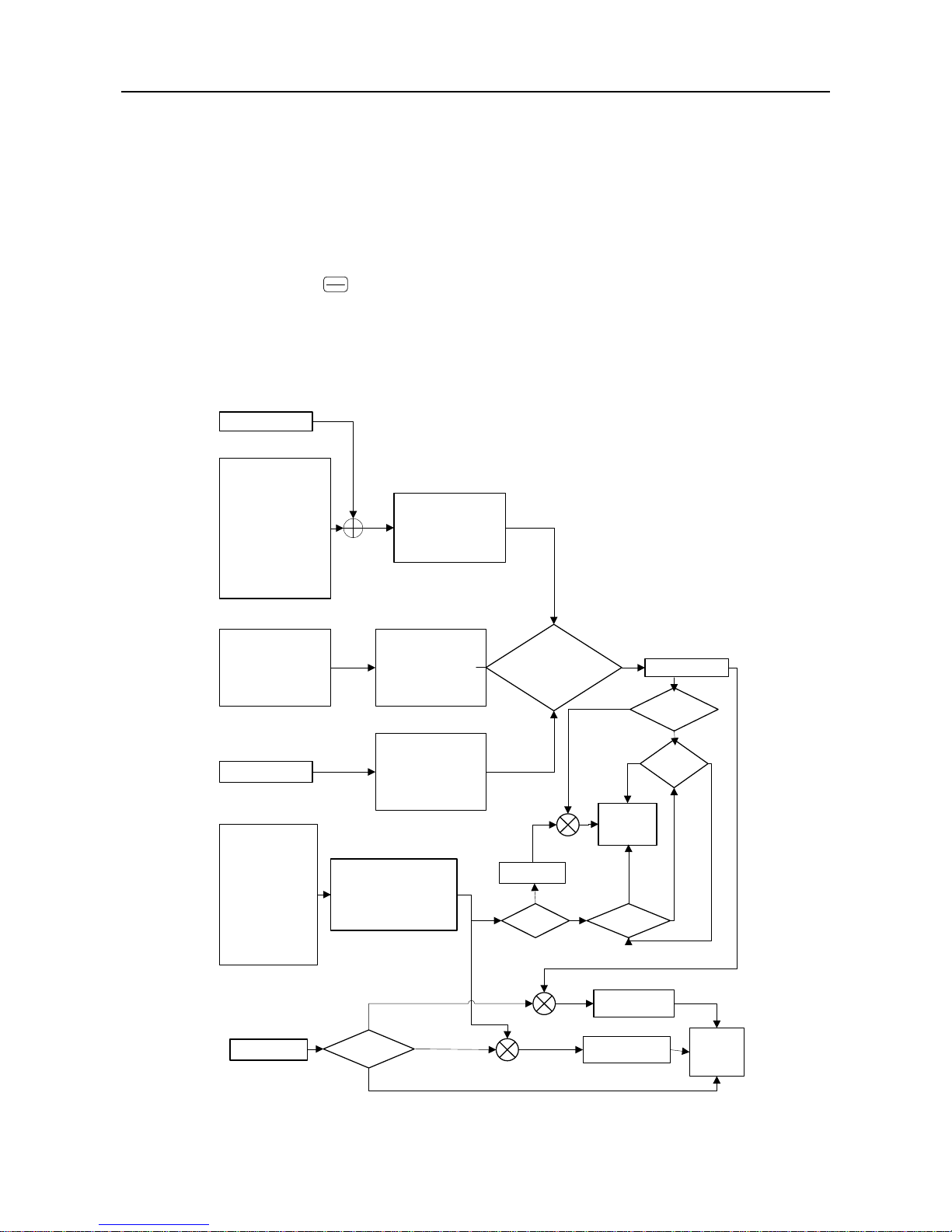
1.2.3 Setting Modes of Inverter
The setting mode of inverter refers to that what kind of physical quantity inverter is taken as
control object when driving motor.
Speed setting mode is to take motor speed as the control object
Torque setting mode is to take motor torque as the control object.
Set through various and flexible methods such as numeric setting, analog voltage, and analog
current or other mathematical combinations. Jog speed setting mode is prior to other setting
modes, i.e. when pressing
JOG
+/-
on keypad or turning control terminals FJOG and RJOG on, no
matter what the present setting mode is, the inverter will automatically switch to jog speed
setting, or the combination of jog speed+primary speed or jog speed+auxiliary speed setting .
See Figure 1-1 and Figure 1-2 for the details of all speed setting modes of EM303B.
F9-04
F9-05
Prior
F9-08: the hundreds place
F0-06
F0-11
F9-08: the ones place
F9-08: the tens place
Regular
Speed
Setting
Mode
Preset Speed1
~Preset Speed 15
0: Primary Numeric Frequency
1: VP Keypad Potentiometer
2: VS
3: IS
4: Not used
5: K3*VS+K4*IS
6: K3*VS+K5*VF
7: K4*IS+K6*IF
8: MAX{K3*VS,K5*VF}
9: MAX{K4*IS,K6*IF}
10:
K1*VP+K2*(K3*VS+K4*IS+
K5*VF+K6*IF-K8*5V)
0: Auxiliary Numeric Frequency
Setting
1: VP Keypad Potentiometer
2: VS
3: IS
4: Not Used
5: K3*VS+K4*IS
6: K3*VS+K5*VF
7: K4*IS+K6*IF
8: MAX{K3*VS,K5*VF}
9: MAX{K4*IS,K6*IF}
10:
K1*VP+K2*(K3*VS+K4*IS+K
5*VF+K6*IF-K8*5V)
0: Program running
1: Wobbulation Running
2: Stepping mode0
3: Stepping mode1
4: Stepping mode2
5: Stepping mode3
6: Stepping mode4
0: Present Setting Value
1: VS*Present Setting Value
2: VF*Present Setting Value
3: IS*Present Setting Value
4: IF*Present Setting Value
0: Present Active Setting Value
1: VS*Present Active Setting Value
2: VF*Present Active Setting Value
3: IS*Present Active Setting Value
4: IF*Present Active Setting Value
0: Present Setting Value
1: VS*Present Setting Value
2: VF*Present Setting Value
3: IS*Present Setting Value
4: IF*Present Setting Value
Jog Speed +
Auxiliary Speed Setting
Jog Speed +
Primary Speed Setting
Jog
Speed
Setting
Result of Process PID
Operation
Regular speed
setting mode is
disabled when
preset speed is
enabled.
Jog Running
Setting Frequency
+
+
+
+
F9-08 sets analog signals(VS/VF/IS/IF/VP)
*Speed setting value.
The analog signals here stand for:
Analog signal voltage/10*100%
Analog signal current/20*100%
OR
0: Present Setting Value
1: VS*Present Setting Value
2: VF*Present Setting Value
3: IS*Present Setting Value
4: IF*Present Setting Value
5: Auxilary Setting*Present
Setting Value
F9-08: the thousands place
=0
F0-26
+
Primary Speed Setting
0:Positive setting
1:Negative setting
Integral
Speed
Setting
F9-03:
the hundreds
place
F3-00~F3-14
F0-07 is the
setting value of
primary numeric
frequency.
F9-03:
The ones place=2
F9-03: The
ones place=2
F9-03:
The ones place =1
F9-03:
The ones
place=0
+
YES
NO
YES
NO
YES
NO
YES
NO
0: Regular Speed Setting
1: Special Speed Setting
2:Process PID Setting
Setting value of
F9-03 tens place
=2
=1
F9-06 is the setting
value of auxiliary
numeric frequency.
Special
Speed
Setting
Mode
Auxiliary
Speed
Setting
Mode
Figure 1-1 Speed Setting Modes
User Manual
EM303B General Purpose Inverter
12
0:Present Setting Value
1:VS*Present Setting Value
2:VF*Present Setting Value
3:IS*Present Setting Value
4:IF*Present Setting Value
F5-11
F5-12 is the setting value of primary numeric torque.
FA-06: the ones place
Torque Setting
0: Primary Numeric Torque Setting
1: VP Keypad Potentiometer
2:VS
3:IS
4:VF
5:IF
6:Not used
7: K1*VP+K2*(K3*VS+K4*IS+
K5*VF+K6*IF-K8*5V)
FA-06 sets analog signals
(VS/VF/IS/IF/VP)*torque setting value.
The analog signals here stand for:
Analog signal voltage/10*100%
Analog signal current/20*100%
Figure 1-2 Torque Setting Mode
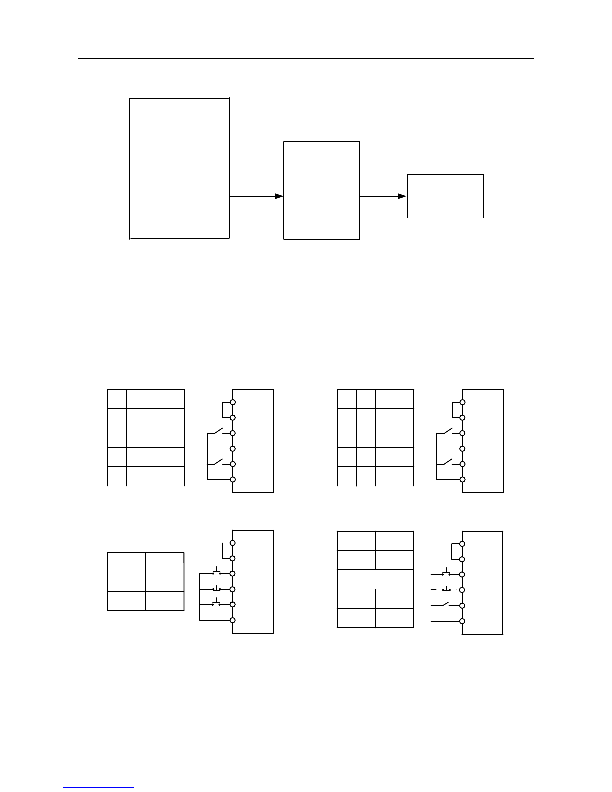
1.2.4 Start/Stop Control Mode of Inverter
The start/stop control mode of inverter refers to the modes to start/stop control of inverter.
There are 3 control modes: keypad control mode, terminal control mode, and RS485
communication control mode. Terminal control mode is categorized as 2-wire sequence, and
3-wire sequence. See Figure 1-3 for the control logic of terminal control mode.
24V
PLC
RUN
Xi
COM
F/R
K1
K2
Run
Command
K2
K1
0 0
0 1
1 0
1
1
Reverse
Forward
Stop
Stop
24V
PLC
RUN
Xi
COM
F/R
K1
K2
Run
Command
K2
K1
0 0
0 1
1 0
1
1
Stop
Forward
Reverse
Stop
0: On 1:Off
0:On 1:Off
(a) 2-wire sequence 0 (F0-05=0) (b) 2-wire sequence 1 (F0-05=1)
Forward
Button
RUN
Stop
Button
24V
PLC
RUN
Xi
COM
F/R
Run
Button
RUN
Xi
F/R
1
0
Stop
Button
Forward
Reverse
0: On 1: Off
( c ) 3-wire sequence 0 (F0-05=2)
(d) 3-wire sequence 1(F0-05=3)
F/R
Xi
Reverse
Button
24V
PLC
RUN
Xi
COM
F/R
Figure 1-3 Control Logic of Terminal Control Mode

User Manual
EM303B General Purpose Inverter
13
1.3 EM303B Outlook
See Figure 1-4 for the outlook of EM303B (Instance: EM303B- 4.0kW).
Keypad
Housing Upper
Nameplate
Housing Base
Mounting Hole
Housing Middle
Mounting Hole
Figure1-4 EM303B Outlook
The housing upper can be disassembled by following the arrow shown in Figure1-4.
See Figure 1-5 for control circuit terminals and main circuit terminals.
Control Circuit Terminal Block
Main Circuit Terminal Block
Figure 1-5 Control Circuit Terminal Block and Main Circuit Terminal Block
S VU W PBR T
User Manual
EM303B General Purpose Inverter
14
2 Installation
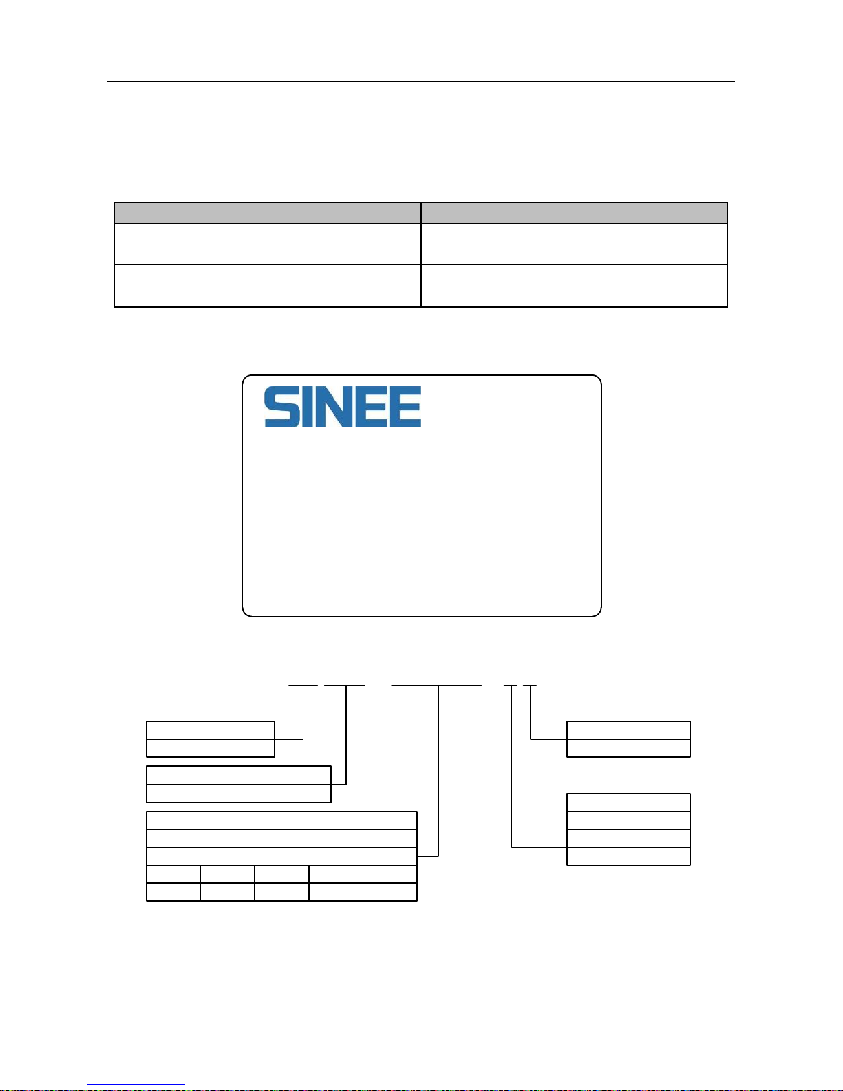
2.1 Verifying Product
Refer to Table 2-1, and check and verify the EM303B.
Table 2-1 Check List
Item
Action
If the products are identical to the purchase
order.
Check the devices reference marked on the
label.
Any part damaged.
Check the outlook if any damages.
Any screw loosened.
Check with a screwdriver if necessary.
Contact the distributor or SINEE directly for quality issue.
Nameplate
Model No. :EM303B-4R0G/5R5P-3B
Rated Power :4.0kW/5.5kW
Input Voltage:380VAC
Rated Current:10.0A/13.0A
Serial No. :
Shenzhen Sine Electric Co., Ltd.
Model Numbering Scheme
Product Category
EM:Inverter
Product Series:
303B:Open Loop Vector Control System
3-phase 380V, 303B is an integrated model with G&P in one.
G: General purpose P: Blower, water pump(Omitted if not specified)
Power Ratings:
0R7
0.75kW
5R5
5.5kW
… …
… …
018
18.5kW
… …
… …
EM 303B – 4R0G/5R5P – 3 B
B:Integrated Braking Unit
None: No Braking Unit
Voltage Class:
1: 1-phase 220V
2: 3-phase 220V
3: 3-phase 380V
User Manual
EM303B General Purpose Inverter
15
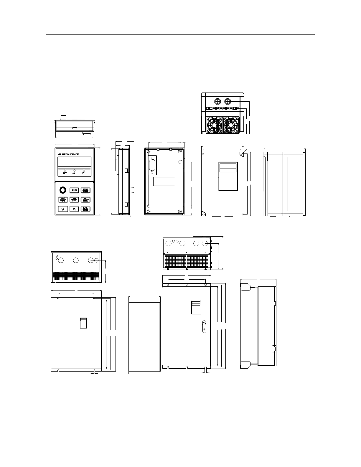
2.2 Overall and Installation Dimensions
EM303B can be classified to 10 sizes for total 30 models. See Figure 2-1 and Table 2-2 for
installation dimensions.
The keypad can be installed on the metal panel separately with a hole size of
116.5±0.1(L)*71.5±0.1 (W)mm, and applicable metal panel thickness:1.2~2.0mm.
-
R
2-M3
71
74
118
26
34
116
8
58
77
16
W1
W
H
H1
D1
D2
D
2
-
<
d
>
(a) (b)
D1
W1
H
H1
H2
2-d
D
W
D
H2
H1
H
W1
W
D1
D2
3-d
(c)( d)
Figure 2-1 Overall and Keypad Dimensions of EM303B

User Manual
EM303B General Purpose Inverter
16
Table 2-2 OverallInstallation Dimensions of EM303B
Model No.
W
W1 H H1
H2 D D1
D2
d
Frame
EM303B-0R7G/1R1P-3B
140
125
220
205
--
152
120
161 6 (b)
EM303B-1R1G/1R5P-3B
EM303B-1R5G/2R2P-3B
EM303B-2R2G/3R0P-3B
EM303B-3R0G/4R0P-3B
EM303B-4R0G/5R5P-3B
EM303B-5R5G/7R5P-3B
165
148
250
235
--
161
126
170 6 (b)
EM303B-7R5G/9R0P-3B
EM303B-9R0G/011P-3B
215
150
352
335
317
215
172
224 7 (c)
EM303B-011G/015P-3B
EM303B-015G/018P-3B
EM303B-018G/022P-3
270
200 470 450
424
245
187
254
10 (c)
EM303B-022G/030P-3
EM303B-030G/037P-3
EM303B-037G/045P-3
335
240 550 530
500
245
190
254
10 (c)
EM303B-045G/055P-3
EM303B-055G/075P-3
390
300 695 665
635
250
200
259
12 (c)
EM303B-075G/090P-3
EM303B-090G/110P-3
386
300 753 724
700
287
231
295
13 (d)
EM303B-110G/132P-3
416
300 855 825
793
302
246
310
13 (d)
EM303B-132G/160P-3
EM303B-160G/185P-3
497
397
1107
1076
1036
335
285
343
13
(d)
EM303B-185G/200P-3
EM303B-200G/220P-3
EM303B-220G/250P-3
656
450
1348
1314
1261
383
232
390
13
(d)
EM303B-250G/280P-3
EM303B-280G/315P-3
EM303B-315G/355P-3
801
680 1417 1383
1330
383
190
390
13 (d)
EM303B-355G/400P-3
EM303B-400G/450P-3
Remarks:
1. 6modes, EM303B-055~075, EM303B-090, EM303B-110~132, EM303B-160~200,
EM303B-220~280,and EM303B-315~400,can be floor-mounted with a chassis which is
in the same width as the inverter. Heights of optional chassis: 120mm, 253mm,
253mm,308mm, 308mmand 355mm. Please order the extra chassis if needed, and see
Section 11.6 for details.
2. EM303B-090~400: power input terminals are on the top, and power output terminals are
at the bottom of the inverter.

User Manual
EM303B General Purpose Inverter
17
2.3 Considerations of Installation Site
2.3.1 Installation Site
Considerations for installation site:
Good ventilation indoor
Ambient temperature: -10C~+40C
No high temperature and high moisture, humidity:<90%RH, no water drops or any
other condensation
Never install on flammable materials
No direct sunlight
No flammable, corrosive gas or liquid
No dust, floating fiber or metal particles
Firm and steady installation base
No electromagnetic interference, and keep away from interference source.
2.3.2 Ambient Temperature
Install inverter in a place with good ventilation to improve the reliability of inverter operation.
When inverter is mounted inside a cabinet, cooling fan or air conditioner is a must. Keep the
ambient temperature below +40C.
2.3.3 Precautions
Please take protective measures during installation to prevent foreign matters like metal
particles or dust from entering the inverter when drilling. After installation, please take off
the protective devices.
2.4 Direction and Space of Installation
Cooling fan(s) installed inside EM303B is for forced air cooling. For good cooling
circulation, please mount inverter vertically, and leave sufficient space between the inverter
and wall or other objects. See Figure 2-2.
Vent
Vent
>120mm
>120mm
>150mm
>150mm
R
-
EM303B
4.0kW
Figure 2-2 Direction and Installation of Inverter

User Manual
EM303B General Purpose Inverter
18
Table 2-3Table of Heat Dissipating Capacity (HDC), Mass Airflow(MAF), Noise and Net
Weight(NW) of Single EM303B
Model No.
Frame
MAF
(CFM)
MAF
(m3/h)
HDC
(W)
Noise
(dB/A)
N.W.
(kg)
EM303B-0R7G/1R1P-3B
Size 1
13
22
65
40
3.15
EM303B-1R1G/1R5P-3B
74
EM303B-1R5G/2R2P-3B
80
EM303B-2R2G/3R0P-3B
110
EM303B-3R0G/4R0P-3B
135
EM303B-4R0G/5R5P-3B
163
EM303B-5R5G/7R5P-3B
Size 2
27
45
185
40
4.3
EM303B-7R5G/9R0P-3B
300
EM303B-9R0G/011P-3B
Size 3
59
100
325
45
12.3
EM303B-011G/015P-3B
385
EM303B-015G/018P-3B
525
EM303B-018G/022P-3
Size 4 80
135
515
56
19.5
EM303B-022G/030P-3
640
EM303B-030G/037P-3
870
EM303B-037G/045P-3
Size 5 165
280
1025
56
30.5
EM303B-045G/055P-3
1158
EM303B-055G/075P-3
Size 6 247
420
1525
56
51.3
EM303B-075G/090P-3
1800
EM303B-090G/110P-3
Size 7
335
570
2120
62
80.2
EM303B-110G/132P-3
Size 8
403
684
2636
62
93.8
EM303B-132G/160P-3
3216
EM303B-160G/185P-3
Size 9
424
720
3881
62
154.8
EM303B-185G/200P-3
4272
EM303B-200G/220P-3
4568
EM303B-220G/250P-3
Size 10
706
1200
4915
73
240
EM303B-250G/280P-3
5442
EM303B-280G/315P-3
6152
EM303B-315G/355P-3
Size 11
706
1200
8098
73
290
EM303B-355G/400P-3
8830
EM303B-400G/450P-3
9418
Remarks:
1. The values listed in the table refer to that the HDC and MAF required when single
EM303B is mounted in an enclosed place.
2. The HDC is calculated based on the rated voltage, rated current and preset carrier
frequency of each model.
3. 3. If more than one EM303B have to be installed in an enclosed place, please add HDC
and MAF.
www.eleris.ru
User Manual
EM303B General Purpose Inverter
19
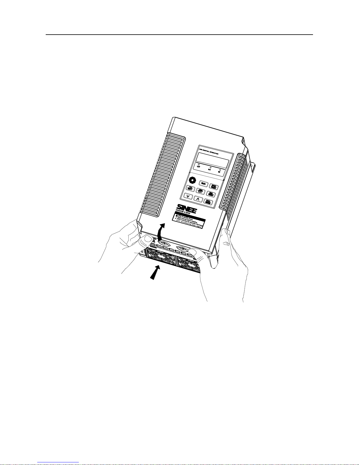
2.5 Disassembly and Assembly of Keypad
Generally it is unnecessary to disassemble the keypad, and just remove the cover to assemble
and wire. On special occasions, disassemble the keypad by following steps.
Remove the front cover: For EM303B-0R7~7R5, push the cover vertically from the
bottom with two hands, and then lift up outwards. See Figure 2-3.
①
②
R
-
①
②
R
-
Figure2-3 Remove the Front Cover
Disassemble the keypad: Put your figures in the insert on the top of keypad, press down
slightly, and pull outwards, then the keypad can be removed. See Figure 2-4.

User Manual
EM303B General Purpose Inverter
20
Figure 2-4 Disassemble the Keypad
Assemble the keypad: Place the bottom of keypad in the slot and then press the top to
push until it clicks into right place. See Figure 2-5.
Figure 2-5 Assemble the Keypad
User Manual
EM303B General Purpose Inverter
21
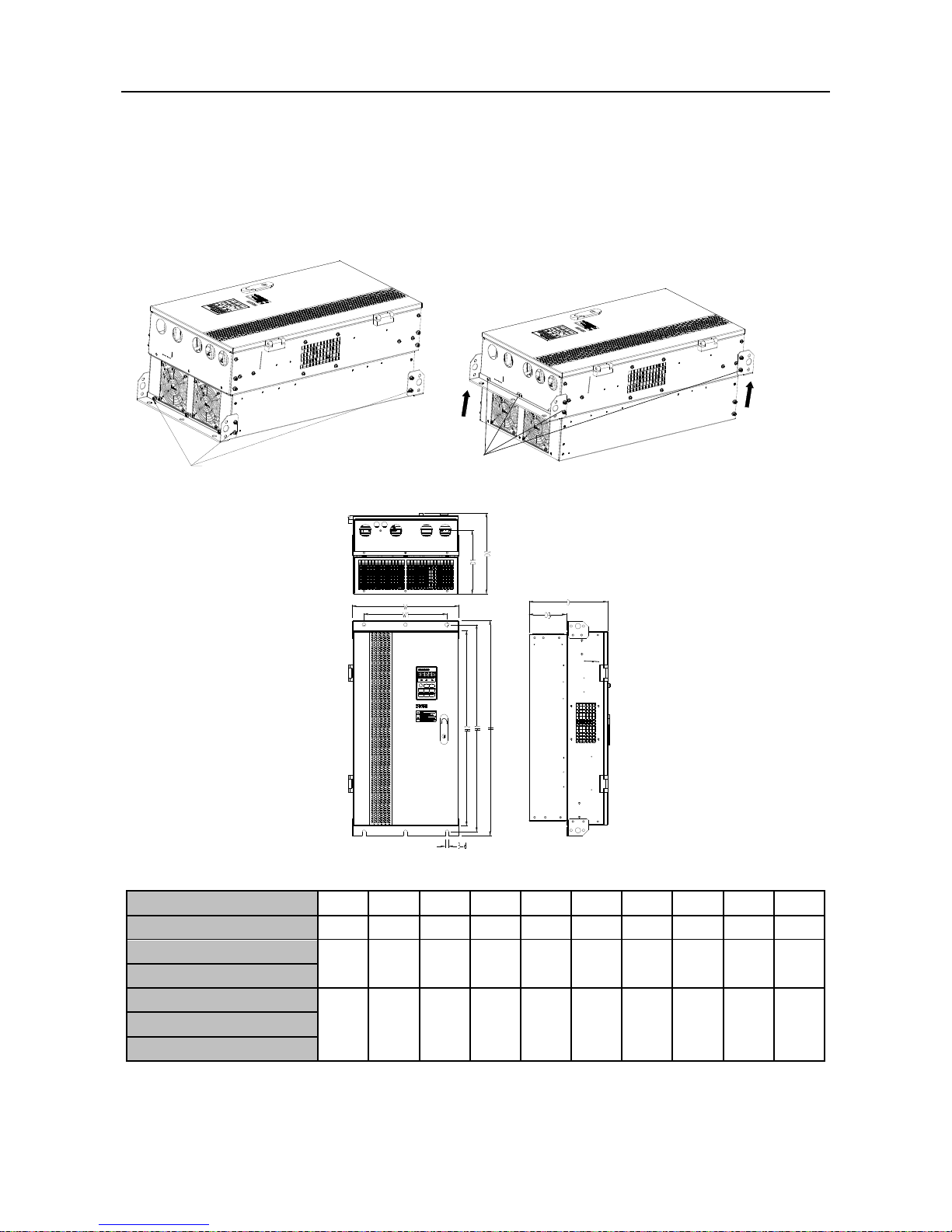
2.6 Flush Mounting
EM303B-090,EM303B-110~132,EM303B-160~200 can be installed in flush mounting.
The mounting method:
Please move the flanges on the top and bottom of the housing from the place as shown in
Figure 2-6 to the place as shown in Figure 2-7. It only needs to unscrew the boltsof flanges
and assemble at the right places. See Figure 2-8 for the installation dimensions.
Unscrew the Bolts
Tighten the Screws
Figure 2-6 Disassembling the FlangesFigure 2-7 Assembling the Flanges
Figure 2-8 Installation Dimensions for Flush Mounting
Model No.
W
W1 H H1
H2 D D1
D2
D3
d
EM303B-090G/110P-3
386
300
753
724
700
287
231
295
136
13
EM303B-110G/132P-3
416
300
855
825
793
302
246
310
132
13
EM303B-132G/160P-3
EM303B-160G/185P-3
497
397
1107
1076
1036
335
285
343
145
13
EM303B-185G/200P-3
EM303B-200G/220P-3
User Manual
EM303B General Purpose Inverter
22
3 Wiring
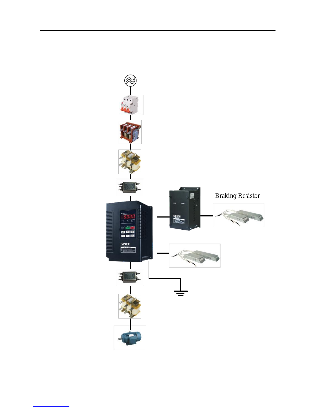
3.1 Connections to Peripherals
Connections between EM303B and its peripherals are shown in Figure 3-1
Mains
Circuit Breaker or
Leakage Switch
Contactor
Input AC Reactor
Input Noise Filter
Inverter
3-phase
Induction Motor
Braking Resistor
Braking Resistor
BR100 Braking Unit
Grounding
Output Noise Filter
Output AC Reactor
Figure 3-1 EM303B Peripherals Connections
User Manual
EM303B General Purpose Inverter
23
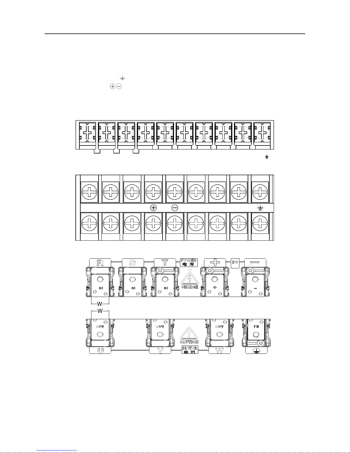
3.2 Wiring Main Circuit Terminals
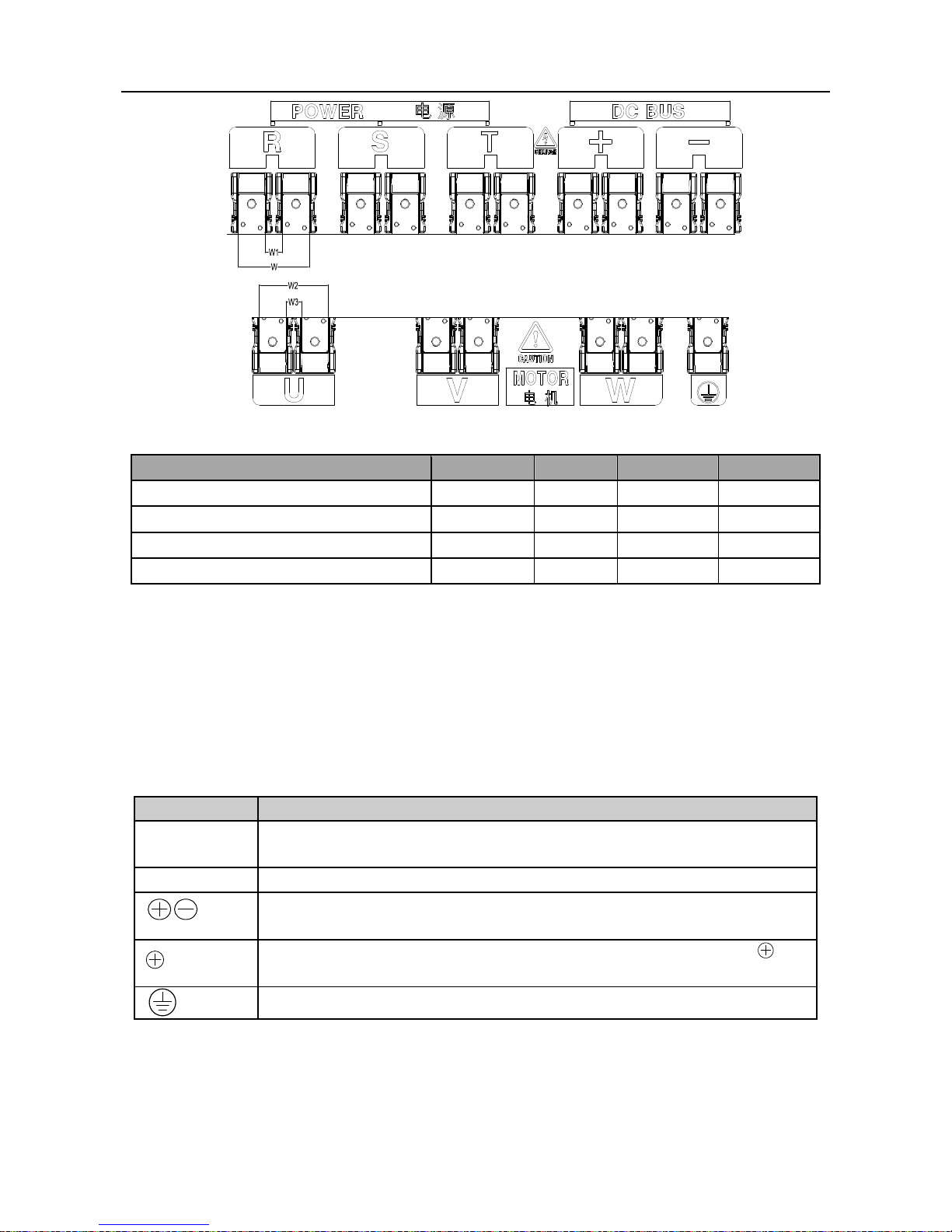
3.2.1 Main Circuit Terminal Block
The main circuit terminals of EM303B are located on the control PCBA:
3-phase AC input terminals: R,S,T
Grounding terminal:
DC bus terminal:
、
Wiring terminal for braking resistor: PB
Output terminals of inverter(For connecting to motor): U, V, W
See Figure 3-2 for main circuit terminal block.
PB
+
○ ○
-
R S T U V W
○
(a) Main Circuit Terminal Block of EM303B-015 or below
TSR WVU
(b) Main Circuit Terminal Block of EM303B -018~075
(c) Main Circuit Terminal Block of EM303B -090~200
User Manual
EM303B General Purpose Inverter
24
(d) Main Circuit Terminal Block of EM303B -220~400
Figure3-2 Main Circuit Terminal Block
Inverter Model No.
W
W1
W2
W3
EM303B-090~132
33 - -
-
EM303B-160~200
39 - -
-
EM303B-220~280
88
22
88
22
EM303B-315~400
104
26
101
23
Remarks:
1. EM303B -090 or above: Power input terminals R, S, and T are on the top, and power
output terminals are at the bottom of the inverter.
2. EM303B -220 or above: There are 2 wiring screws for each terminal.
3.2.2 Main Circuit Terminal Functions
The main circuit terminal functions of EM303B are listed in Table 3-1. Please wire the
terminals correctly as per corresponding function.
Table 3-1 Main Circuit Terminal Functions
Terminal
Function
R、S、T
AC power input terminals for connecting to 3-phase AC power.
(Terminal L1, L2 for AC220V 1-phase input inverter)
U、V、W
Inverter AC output terminals for connecting to 3-phase induction motor.
Positive and negative terminals of internal DC bus for connecting to
external braking unit.
、PB
Connecting terminals of braking resistor, one end connected to and
the other to PB.
Grounding terminals
User Manual
EM303B General Purpose Inverter
25
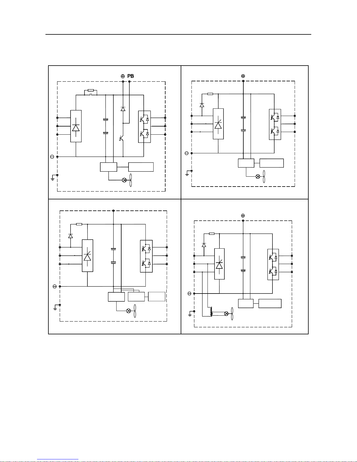
3.2.3 Internal Main Circuit
See Figure 3-3 for the internal main circuit structure of EM303B.
Figure 3-3 Internal Main Circuit
EM303B-0R7~015
Control CircuitMains
Cooling Fan
U
V
WT
S
R
EM303B-018~30
R
S
T W
V
U
Cooling Fan
Mains Control Circuit
EM303B-37~200
R
S
T W
V
U
Cooling Fan
Mains for
Fan
Control
Circuit
Mains
EM303B-220~400
R
S
T W
V
U
Cooling Fan
Mains
Control
Circuit
3.2.4 Standard Wiring of Main Circuit
See Figure 3-4 for standard wiring of main circuit.
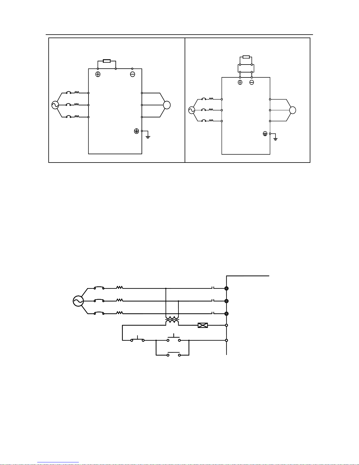
User Manual
EM303B General Purpose Inverter
26
EM303B-0R7~015
Braking Resistor
(Optional)
PB
M
U
V
WT
S
R
EM303B-018~400
Braking Resistor(Optional)
Braking Unit(Optional)
M
U
V
WT
S
R
Figure 3-4 Standard Wiring of Main Circuit
3.2.5 Wiring Main Circuit on Input Side
Installing a Circuit Breaker
Always install an air circuit breaker (MCCB) between the power supply and input terminals.
Choose a MCCB with a capacity of 1.5-2 times of the inverter’s rated current.
The time characteristics of MCCB should meet that of inverter’s overheating protection
(150% of rated current /1 minute).
If single MCCB is shared by two or more inverters or other devices, the contact of fault
output relay shall be connected to power contactor coil, so that the power supply will be
turned off by the fault signals, as shown in Figure 3-5.
Fault Relay
Contact
EC
EB
MC
OFF
MC
ON
MCCB
T
S
R
EM303B
Figure 3-5 Connecting to Input Circuit Breaker
Installing a Leakage Circuit Breaker
High frequency leakage current is generated by high frequency PWM signal output of
inverter. Select a special purpose leakage breaker with a trigger current≥30mA. For a regular
leakage breaker, the trigger current≥200mA and the active time at 0.1S or above.
Installing an Electromagnetic Contactor
Install an electromagnetic contactor which is applicable to inverter as shown in Figure 3-5.
User Manual
EM303B General Purpose Inverter
27
Start/stop of the inverter can be controlled by the electromagnetic contactor on input side.
Inverter may break down if the electromagnetic contactor is on and off frequently. The
operation interval between start and stop of the inverter shall ≥ 30 minutes.
The inverter will not automatically start after power failure.
Connecting to the Terminal Block
Power input phase sequence is not related to the phase sequence of terminals R, S, and T on
the terminal block, any two of them can be connected randomly.
Installing an AC Reactor
If the inverter is connected to a transformer with big-capacity (≥600kVA), or power supply is
connected to capacitive load, an excessive big surge current will occur and rectifier of
inverter can be broken down. Install an optional 3-phase AC reactor on input side of inverter
to suppress peak current and voltage, and improve power factor of the system.
Installing a Surge Absorber
Install a surge absorber for inductive loads (electromagnetic contactors, solenoid valves,
solenoid coils, or electromagnetic circuit breakers) nearby the inverter.
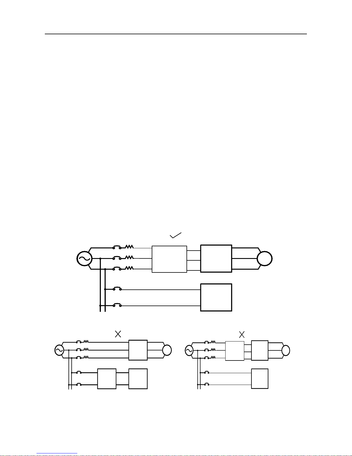
Installing a Noise Filter on Power Supply Side
To filter noise transmitted between power cable and the inverter, andthe harmonic
distortionof power grid caused by the noise produced by the inverter.
A special purpose noise filter is required for the inverter.
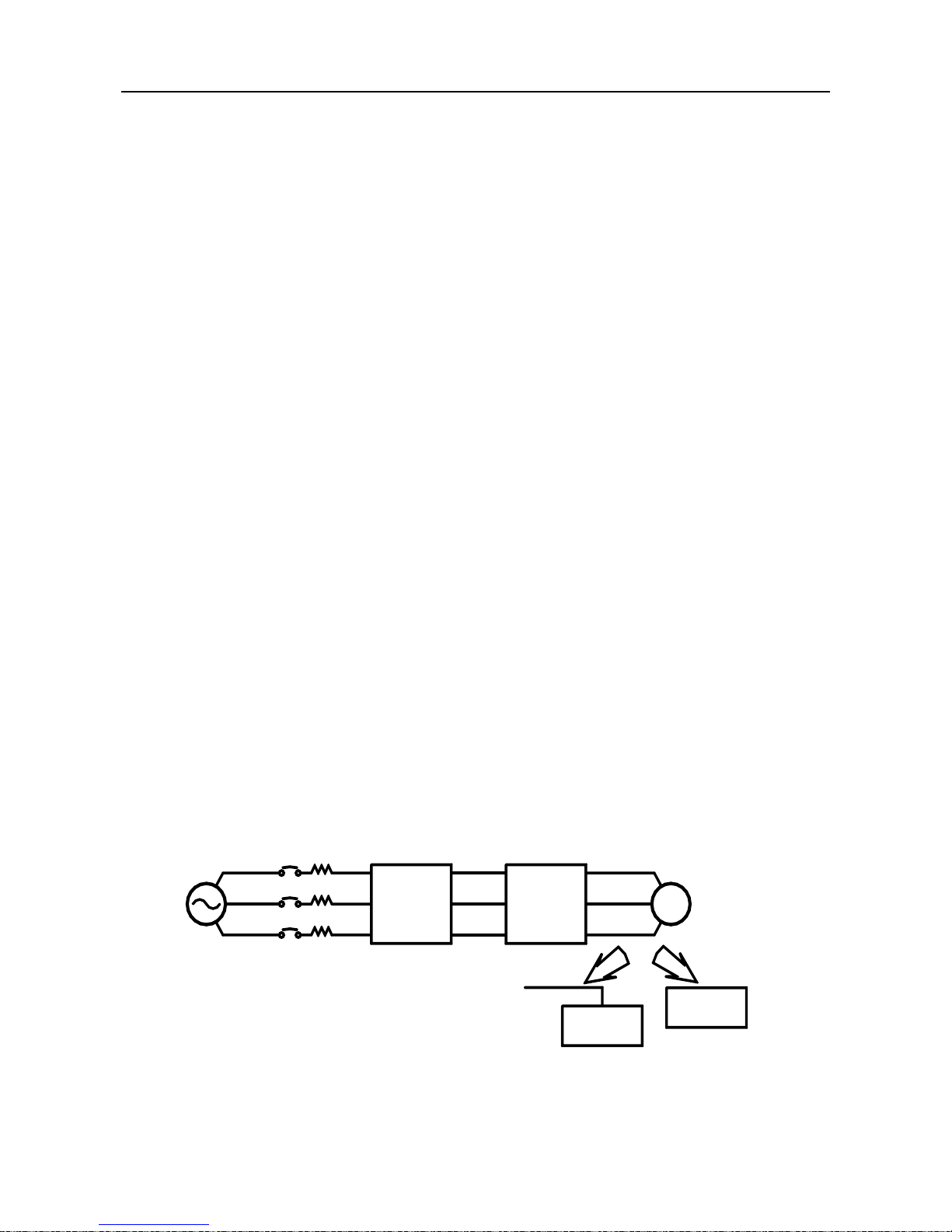
Correct vs incorrect installations of noise filters as shown in Figure 3-6 and Figure 3-7.
MCCB
Special
Purpose
Noise Filter
Other
Control
Devices
EM303B
Inverter
IM
EMC
Figure 3-6 Correct Noise Filter Installation
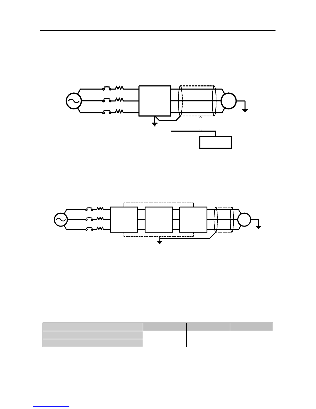
MCCB
Regular
Noise
Filter
Other
Control
Devices
EM303B
Inverter
IM
MCCB
Regular
Noise
Filter
Other
Control
Devices
EM303B
Inverter
IM
(a)
(b)
Figure 3-7 Incorrect Noise Filter Installation
User Manual
EM303B General Purpose Inverter
28
3.2.6 Wiring the Output Side of Main Circuit
Connecting the Inverter to Motor
Connect inverter output terminals U, V, and W to motor input terminals U, V and W.
Confirm that the motor forwards with the Forward Command. Switch any 2 of the
inverter output terminals U, V, or W to each other and reconnect if the motor reverses.
Never Connecting Power Supply Cable to Output Terminals
Never connect power supply cable to output terminals. If the output terminalsare connected
to power supply, the inverter would be damaged.
Never Short-Circuiting or Grounding Output Terminals
Never touch output terminals directly with bare hands, or connect the output cable to the
housing of inverter. Otherwise, an electric shock and short-circuit may occur. Furthermore,
do not short-circuit the output cable.
Never Using a Phase-shifting Capacitor
Never connect phase-shifting electrolytic capacitor or LC/RC filter to the output circuit.
Otherwise, inverter will be damaged.
Never Using an Electromagnetic Switch
Never connect electromagnetic switch or electromagnetic contactor to the output circuit.
Otherwise, failure to comply will cause overcurrent or overvoltage protection. Even
worse, inverter will be damaged.
Please make sure that the inverter stops before installing electromagnetic contactor to
switch grid power supply.
Installing a Noise Filter on the Output Side
Install a noise filter on the output side of inverter to reduce inductive interference and radio
interference.
Inductive interference: Electromagnetic induction generates noise on the signal line
which may cause the control device malfunction.
Radio interference: The high frequency electromagnetic waves generated by inverter and
cable cause radio devices nearby to make noise when receiving signals.
MCCB
EM303B
Inverter
Noise
Filter
Control
Device
Radio Device
Signal Line
Inductive
Interference
Radio Frequency
Interference
IM
Figure 3-8 Installing a Noise Filter on the Output Side
User Manual
EM303B General Purpose Inverter
29
Countermeasures Against Inductive Interference
As stated previously, except installing a noise filter, all output cables can be routed through a
grounded metal pipe to prevent inductive interference on the output side. The distance
between output cables and signal line should>30cm, and the inductive interference will be
reduced considerably, as shown in Figure 3-9.
MCCB
Signal Line
30cm MIN
Metal Pipe
IM
Control
Device
EM303B
Inverter
Figure 3-9 Countermeasures Against Inductive Interference
Countermeasures Against Radio Frequency Interference (RFI)
RFI will be generated from the inverter as well as the input cable and the output cable. Install
noise filters on both input and output sides, and shield inverter with an iron case to reduce
RFI. As shown in Figure 3-10.
MCCB
Noise
Filter
EM303B
Inverter
IM
Iron Case
Metal Pipe
Noise
Filter
Figure 3-10 Countermeasures Against RFI
Cable Length Between Inverter and Motor
The longer cable between the inverter and motor is, the higher carrier frequency is, and the
greater high-frequency harmonic leakage current on its cable is. All of which will affect
inverter and its peripherals. See Table 3-2 to adjust carrier frequency for reducing the
high-frequency harmonic leakage current.
When motor cable>50m, please connect a special 3-phase AC reactor of the same capacity
as that of the inverter to the output terminals.
Table 3-2 Cable Length and Carrier Frequency Between Inverter and Motor
Cable Length
<50m
<100m
>100m
Carrier Frequency
<10kHz
<8kHz
<5kHz
F0-14 Function Parameter
10.000
5.000
2.000
User Manual
EM303B General Purpose Inverter
30
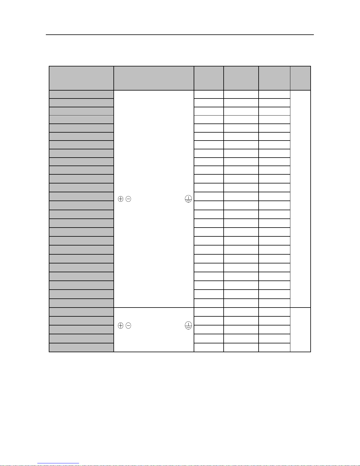
3.2.7 Main Circuit Cable and Terminal Screw Size
See Table 3-3 for the specifications of main circuit cable and terminal screw.
Table 3-3 Main Circuit Cable and Terminal Screw Specifications
Model No.
Terminals
Terminal
Screw
Tightening
Torque
(N.m)
Cable
Size
(mm2)
Cable
Type
EM303B-0R7G/1R1P-3B
M3.5
1.2~1.5
1.5
750V
EM303B-1R1G/1R5P-3B
M3.5
1.2~1.5
2.5
EM303B-1R5G/2R2P-3B
M3.5
1.2~1.5
2.5
EM303B-2R2G/3R0P-3B
M3.5
1.2~1.5
4
EM303B-3R0G/4R0P-3B
M3.5
1.2~1.5
4
EM303B-4R0G/5R5P-3B
M3.5
1.2~1.5
4
EM303B-5R5G/7R5P-3B
M4
1.5~2.0
6
EM303B-7R5G/9R0P-3B
M4
1.5~2.0
6
EM303B-9R0G/011P-3B
M5
3.0~4.0
6
EM303B-011G/015P-3B
M5
3.0~4.0
10
EM303B-015G/018P-3B
M5
3.0~4.0
10
EM303B-018G/022P-3
M6
4.0~5.0
16
EM303B-022G/030P-3
M6
4.0~5.0
16
EM303B-030G/037P-3
M6
4.0~5.0
25
EM303B-037G/045P-3
M8
9.0~10.0
25
EM303B-045G/055P-3
M8
9.0~10.0
35
EM303B-055G/075P-3
M10
17.0~22.0
35
EM303B-075G/090P-3
M10
17.0~22.0
60
EM303B-090G/110P-3
M10
17.0~22.0
60
EM303B-110G/132P-3
M10
17.0~22.0
90
EM303B-132G/160P-3
M10
17.0~22.0
90
EM303B-160G/185P-3
M12
31.0~39.0
120
EM303B-185G/200P-3
M12
31.0~39.0
180
EM303B-200G/220P-3
M12
31.0~39.0
180
EM303B-220G/250P-3
2*M10
17.0~22.0
2*120
EM303B-250G/280P-3
2*M10
17.0~22.0
2*120
EM303B-280G/315P-3
2*M10
17.0~22.0
2*150
EM303B-315G/355P-3
2*M12
31.0~39.0
2*150
EM303B-355G/400P-3
2*M12
31.0~39.0
2*150
EM303B-400G/450P-3
2*M12
31.0~39.0
2*180
Remarks:
1. Take the voltagedrop into consideration for selecting cable. Generally the voltagedrop
should be<5V and calculated according to following formula:
Voltagedrop=√3* Cable resistance ratio (Ω/KM)*Cable length (m)*Rated current (A)*10
-3
2. If placed in plastic duct, the cable should be uprated by one level.
3. The cable should be connected to the applicable cable and wiring terminal.
4. The size of grounding cable should be the same as that of power cable when the size of
power cable is less than 16mm2. However, when the size of power cable>16mm2, the size
of grounding cable should not be less than half of it, but at least16mm2.
,
,R,S,T,U,V,W,PB,
,
,R,S,T,U,V,W,PB,
 Loading...