

Elephant M40D, M40, M65, M65-D Installation Manual
Installation Guide / Montageanleitung / Montagevejledning
Installationsanvisningar / Montagehandleiding
UK · D · DK · SV · NL
Elephant M40, M40D, M65, M65-D,
ElephantSMART M Serie A+D
230V Energizers-Dual-SMART
700034011_230V_M40-M40D-M65-M65D-Smart M SerieA+D_A5.indd 1 03-05-16 15:50
Elephant M40, M40D, M65, M65-D,
Elephant SMART M Serie A+D
Table of contents
1 Introduction 3
2 Positioning the energizer 4
2.1 General 4
2.2 Wall tting 4
3 Explanation of symbols and display 4
3.1 Output symbols all models 4
3.2 Elephant M40 5
3.2 Elephant M40-D, M65, M65-D 5
3.3 Elephant SMART M series A+D 5
4 Elephant SMART A+D TIME DELAY and POWER MODE 6
4.1 Elephant SMART general 6
4.2 Signals when TIME DELAY and POWER MODE are active 6
5 Earth connection 6
5.1 Earth connection general 6
5.2 Position earth peg 6
5.3 Fit earth cable 6
5.4 Test earthing 7
6 Connection to fence 7
6.1 Fit fencing cable - Full power 7
6.2 Fit fencing cable - Reduced power 7
7 Troubleshooting 8
8 Practical tips 8
9 Guarantee 9
10 Important information 9
2
UK
Installation Guide
700034011_230V_M40-M40D-M65-M65D-Smart M SerieA+D_A5.indd 2 03-05-16 15:50

3
1 Introduction
Congratulations, you are now the owner of a high-quality Elephant Electric Fence.
To obtain the maximum benet from your Elephant Electric Fence for as many years as
possible, it is important that you give the product the best possible operating conditions.
When the device is in operation it can run both indoors and outdoors, and has no problems
withstanding difcult weather conditions with heavy precipitation and signicant temperature
uctuations. This is because the “inbuilt” heating from the device’s modest power
consumption is sufcient to keep the electronic components free of moisture.
When the device is not in operation it should be stored indoors under stable temperature
conditions.
You must therefore not allow your electric fence to hang outdoors for long periods without
power, as moisture and condensation will act very quickly (particularly during the winter) to
damage PCBs and electronic components, which will thus destroy the electric fence.
To give your electric fence extra protection against wind and weather, you must not cover the
electric fence with, for example, a plastic bag. This will have the effect that the electric fence
is unable to breathe. In many instances moisture will be created, with the consequence that
the electric fence’s electronic components will be damaged in a very short time (2-6 months).
Battery fences and mobile fences that are connected to batteries (with an acid content) must
be protected so that steam from the battery does not come into contact with the electronic
components in the electric fence.
If an electric fence breaks down because of the above, the guarantee is rendered invalid.
Check your local ordinance on fencing laws: local laws may require a permit before use.
700034011_230V_M40-M40D-M65-M65D-Smart M SerieA+D_A5.indd 3 03-05-16 15:50

4
2 Positioning the energizer
2.1 General
Before you start the installation of the controller it is important that the instructions are
studied carefully. A correct installation is essential if you want an optimal functionality of your
Energizer.
The energizer sends electrical pulses along the fence line, about one second apart. These
pulses give the animal a short, sharp, but safe shock. The shock doesn’t harm the animal.
Itis sufciently memorable that the animal never forgets the shock, and will avoid the fence.
Fit the energizer to a wall, protected from the weather.
Keep the energizer away from children. Install the energizer in such a way that there cannot
be any chance of re or mechanical damage.
Where possible, keep the energizer away from heavy-duty electrical equipment, such as
pumps, heavy-duty electric motors, high-voltage pylons and other objects that could cause
electrical interference.
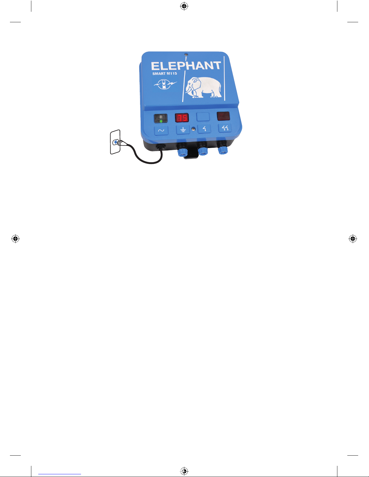
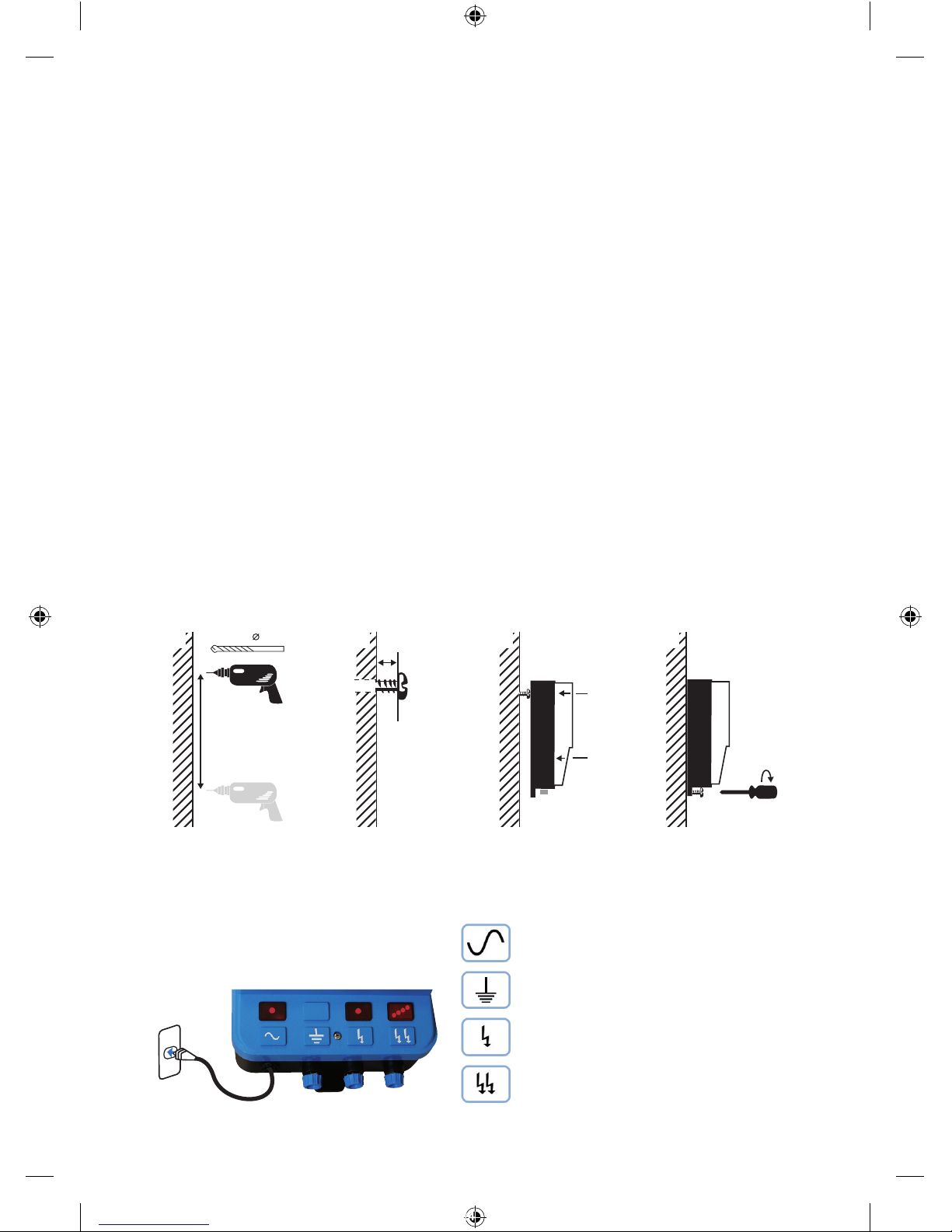
2.2 Wall fitting
a) Determine the position of the energizer and drill 2 holes of 6mm with 260mm (vertical) in
between the two holes.
b) Put the supplied plugs in the wall and screw one of the two supplied screws in the top
plug, making sure the screw sticks out approximately 10mm from the wall.
c) Place the top tting hole of the energizer over the screw.
d) Now put the 2nd screw in the bottom hole and turn it nger tight.
3 Explanation of symbols and display
3.1 Output symbols all models
6mm
10mm
260mm
A B C D
Cable with plug for 230V main.
Earth Clips to be connected to the
earthrod.
Fence Clips (medium output) for smaller
fencing application.
Fence Clips (high output) for larger
fencing application.
700034011_230V_M40-M40D-M65-M65D-Smart M SerieA+D_A5.indd 4 03-05-16 15:50
5
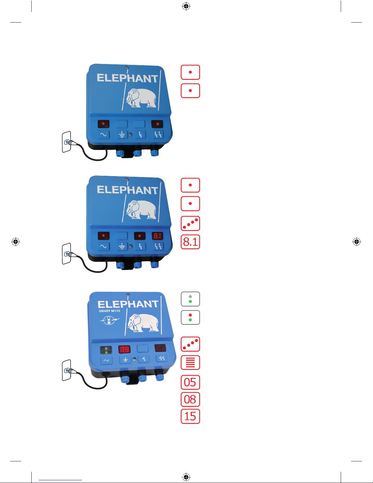
3.2 Elephant M40
3.3 Elephant M40-D, M65, M65-D
3.4 Elephant SMART M Serie A+D
*See 4.2 for an explanation of the
POWER MODE settings.
Lights when the energizer is ON
M40. Flashes when the voltage
is above 2000V.
Lights when the energizer is ON
Flashes red for every pulse.
M65, Voltage indicator, 4 LEDs, (@ 1,000Volt)
1,000V, 2,000V, 3,000V and 4,000 Volt.
M40D, M65D, Voltage can be read
on display in kV.
Green LED light comes on, device is
switched on.
Red LED light comes on, Alarm / TIME
DELAY switched on. (You hear a buzzer
signal)
Voltage indicator, in 5 increments of 2kV
(2kV, 4kV, 6kV, 8kV and 10kV)
For 5 pulses the digital display shows
the output voltage in kV, followed by the
mode status of the device for 1 pulse:
05 Mode, Standard mode 5 Joule
08 Mode, POWER MODE 08 Joule
15 Mode, POWER MODE 15 Joule
700034011_230V_M40-M40D-M65-M65D-Smart M SerieA+D_A5.indd 5 03-05-16 15:50

6
4 Elephant SMART A+D TIME DELAY and POWER MODE
4.1 Elephant SMART general
The energizers of the Elephant SMART series (A+D) all have a TIME DELAY and POWER
MODE function. These energizers continuously monitor the performance of your fencing
and anticipate changes in the fence. In the event of a sudden voltage drop on the fence,
the Elephant SMART switches automatically to TIME DELAY mode and the voltage will be
increased.
4.2 Signals when TIME DELAY and POWER MODE are active
If TIME DELAY is activated,
• the red alarm LED comes on,
• you hear a repeating sound signal (buzzer),
• the standard outgoing pulse time reduces from 1.3 seconds to 1 pulse every 3 seconds,
• the POWER MODE is switched on
The TIME DELAY mode remains switched on for approximately 9 minutes and then the
signals (alarms) go off and the time between the pulses returns to the standard interval of
1.3 seconds. The POWER MODE position that is needed to keep the fence at the highest
possible voltage remains switched on.
Explanation of the POWER MODE positions,
• 05, Normal mode, the energizer works in the standard 5 joule mode.
• 08, POWER MODE, the device will build up to max 8 Joule energy.
• 15, POWER MODE, the device will build up to max 15 Joule energy.
5 Earth connection
5.1 Earth connection general
To connect the earthing it is important to use galvanised materials, because they produce a
good connection. Other material may oxidise. With poor contacts the system does not work
properly and they may cause faults.
Always comply with the earthing instructions!
Important! Make sure the earth pegs are at least 4 metres apart and at least 10 metres away
from any surrounding electrical cabling. Poor earthing may cause interference with telephone,
radio and television lines. There is interference if you hear a clicking noise during a telephone
conversation.
5.2 Positioning the earth peg
Position at least 1x1metre (SMART M series A+D at least 2x2metres) galvanised earth peg
(art. no 055853) if possible in damp ground. In dry conditions or in areas with a low level of
minerals in the soil, you generally need several earth pegs!
Earth pegs should be at least 4 metres apart and at least 10 metres away from electricity
cables, telephone cables, water pipes or earthing of buildings. Never connect an earth cable
to a metal object of a building.
5.3 Fit earth cable
a) Use *1.6mm2 or 2.5mm insulated earth cable. Remove approximately 2cm of the plastic
sleeve on one side of the earth cable and connect it to the blue left connection knob under
the symbol of the energizer. Tighten the knob until the wire is clamped down.
b) At the other end of the earth cable, remove approximately 10cm of the plastic sleeve and
connect the released wire with an earth clamp to the earth peg. Tighten the clamp.
700034011_230V_M40-M40D-M65-M65D-Smart M SerieA+D_A5.indd 6 03-05-16 15:50
7
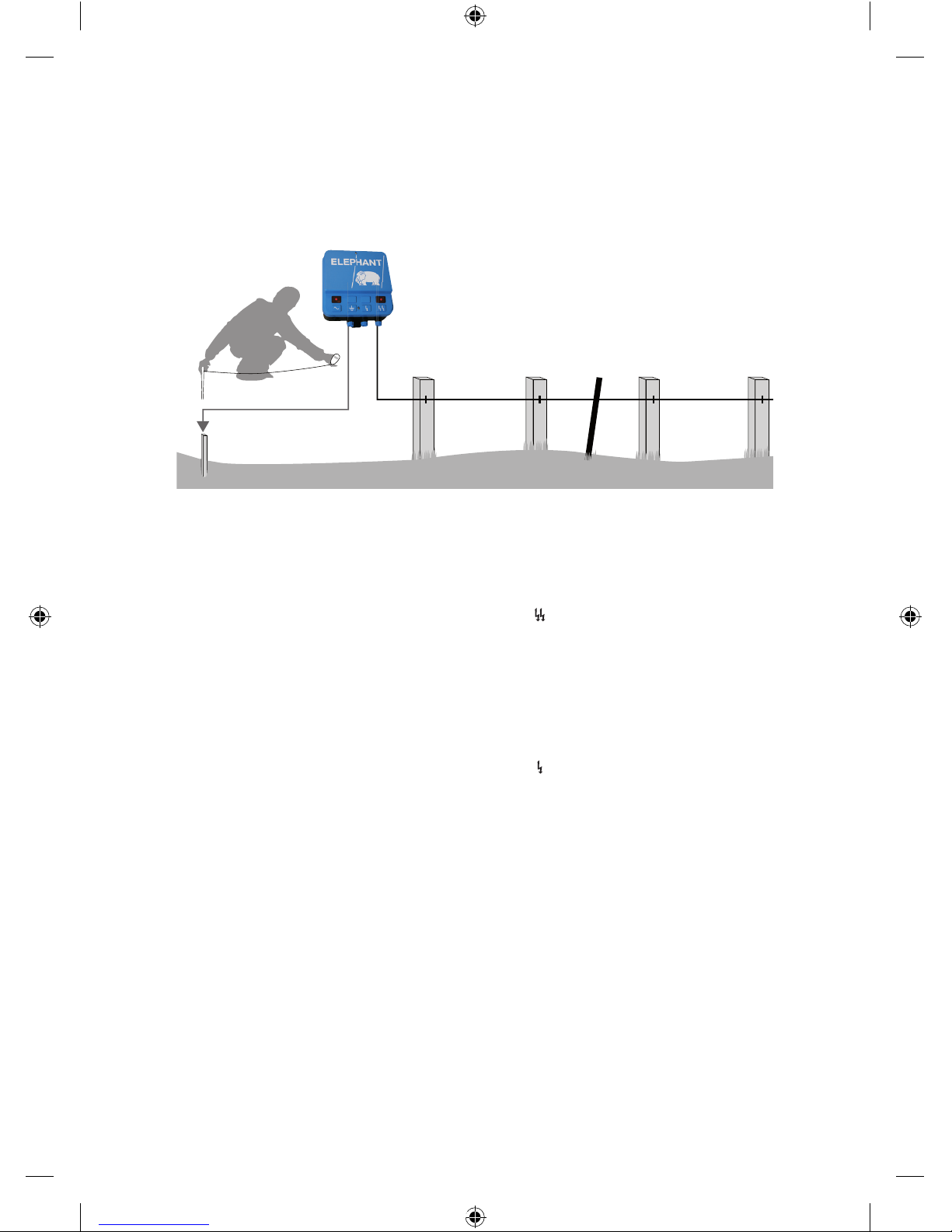
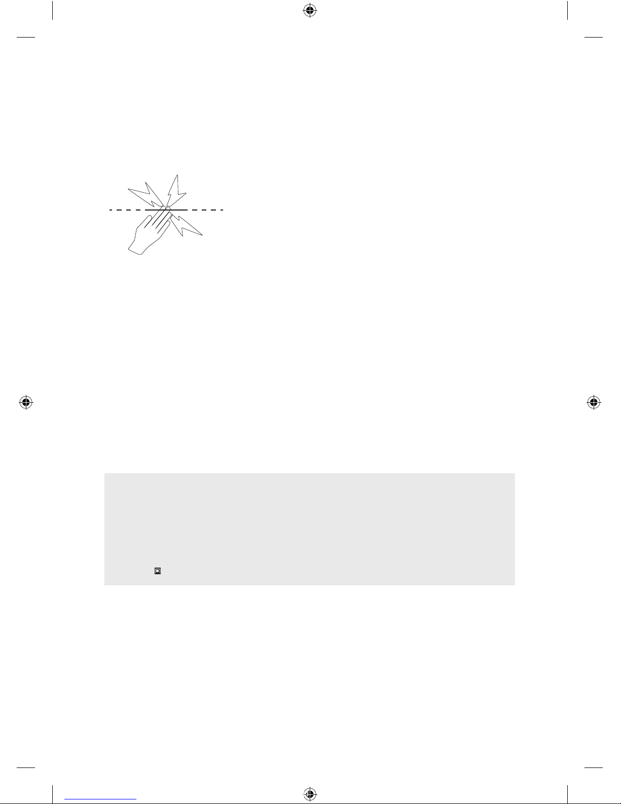
5.4 Testing your fence/earth connection
At least a 100 mtrs away from the earthing system, measure with a digital voltmeter
(art.no4002227) if the current is more than 3000 V. Create a short circuit by putting iron
posts against the fence-wire. If the current measured on the earthing system is more than
300V more earthing rods need to be placed (distance 3 mtrs). Repeat the test.
6 Connecting the fencing
6.1 Fit fencing cable - Full power
a) Use *1.6mm2 or 2.5mm insulated earth cable.
Remove approximately 2cm of the plastic sleeve on one side of the earth cable and
connect it to the blue left connection knob under the symbol. Tighten the knob until the
wire is clamped down.
b) At the other end of the earth cable, remove approximately 4cm of the plastic sleeve and
connect the released wire with an earth clamp (Elephant art.no 056026) to the fencing.
Tighten the clamp.
6.2 Fit fencing cable - Reduced power
a) Use *1.6mm2 or 2.5mm insulated earth cable.
Remove approximately 2cm of the plastic sleeve on one side of the earth cable and
connect it to the blue left connection knob under the symbol. Tighten the knob until the
wire is clamped down.
b) At the other end of the earth cable, remove approximately 4cm of the plastic sleeve and
connect the released wire with an earth clamp (Elephant art.no 056026) to the fencing.
Tighten the clamp.
* When distances exceed 200m a lower resistance cable is required.
Elephant recommends for a distance of up to 100m 1.6mm2 earth cable
(Elephant art.no 4002500), and for a distance over 100m 2.5mm2 earth cable
(Elephant art.no 4002524).
Temporary short-circuit approx. 100m
from the energizer
700034011_230V_M40-M40D-M65-M65D-Smart M SerieA+D_A5.indd 7 03-05-16 15:50
8
7 Troubleshooting
Problem Cause Solution
Not enough voltage on the fence. Short circuit/vegetation in the
fence
Remove short circuit/vegetation
More voltage at the start of the
fence than at the end.
Poor earthing/connections/short
circuit/vegetation in the fence/
earthing system is inadequate.
Check the connections of
the earthing system. Perform
Earthing test, add extra earth
pegs.
Earth voltage is too high. Poor earthing/Earthing system is
inadequate.
Check the connections of
the earthing system. Perform
Earthing test, add extra earth
pegs.
When fence is disconnected,
device does not produce more
than 6,000V.
Device broken Send for repair.
Interferes with devices. Poor contacts / ashover Repair and replace if necessary.
Animals don’t seem bothered by
the shock.
Animals need time to learn to
respect electric fencing.
This can take a few days.
You can hear and see sparks
ash over on the fence.
Poor connections, worn or old
insulators, particularly on iron
posts
Replace those.
No output voltage. Device broken Send for repair.
8 Practical Hints
• All animals need time to learn to respect the fence. It may take several days to train the
animal and the fence may require minor adjustments.
• Animals that are prone to jumping may be difcult to conne. You may need to try different
fence heights to determine the best height.
• Use top quality insulators: low quality or cracked insulators and plastic tubing are not
recommended because they will cause shorting.
• Use joint clamps on all steel wire connections to ensure a high quality circuit.
• This energizer must be earthed using galvanised metal earth stakes to ensure the electric
fence works correctly.
• Double Insulated Cable should be used in buildings, under gateways and where soil could
corrode exposed galvanised wire. Never use household electrical cable. It is made for a
maximum of 600 volts and will leak electricity.
• On permanent power fencing, use high tensile 12.5 gauge (2.5 mm) wire.
• Check the fence periodically. Remove any fallen branches, weeds or shrubs because these
will cause the fence to short out and will reduce animal control.
700034011_230V_M40-M40D-M65-M65D-Smart M SerieA+D_A5.indd 8 03-05-16 15:50

9
9 Guarantee
If the device is not working properly, you can return it to Elephant for guarantee and repair.
The guarantee period starts on the day of purchasing the product and is 3 years for Elephant
energizers.
Keep your proof of purchase. A guarantee repair cannot be performed without the original
proof of purchase.
What is guaranteed?
If your energizer comes under our guarantee conditions, we determine whether it will be
repaired or replaced. Consumables (components that are expected to be replaced during
the lifespan of the product) are not covered by the guarantee. This includes batteries, cables,
plugs, knobs and other such accessories.
Guarantee becomes repair
If it becomes clear during repair that the defect was caused by improper use and it does not
come under the guarantee, we reserve the right to charge you for the repair or the new price.
The guarantee does not cover damage due to external inuences, mindless damage, unsuitable use, changes to the energizer, expansion and adding foreign components, et cetera.
10 Important Information
WARNING: READ ALL INSTRUCTIONS
• Do NOT touch the fence with the head, mouth, neck or torso. Do not climb over, through or
under a multi-wire electric fence. Use a gate or a specially designed crossing point.
• Do NOT become entangled in the fence. Avoid electric fence constructions that are likely to
lead to the entanglement of animals or persons.
• Energizer must be installed in a shelter and the supply cord must not be handled when the
ambient temperature is below +5 deg C.
• Ensure the Energizer is fully protected from rain, condensation and other sources of moisture.
• Do not mount in places exposed to heat sources (e.g. a sun heated metal wall.)
• Ensure the Energizer has adequate ventilation.
• Electric animal fences shall be installed and operated so that they cause no electrical hazard to
persons, animals or their surroundings.
• It is recommended that, in all areas where there is a likely presence of unsupervised children
who will be unaware of the dangers of electric fencing, that a suitably rated current limiting
device having a resistance of not less than 500 ohms be connected between the energizer and
the electric fence in this area.
• The appliance is not intended for use by young children or inrm persons without supervision.
• Young children should be supervised to ensure that they do not play with the appliance.
• Do not place combustible materials near the fence or energizer connections. In times of
extreme re risk, disconnect energizer.
• Regularly inspect the supply cord and energizer for any damage. If found damaged in any way,
immediately cease use of the energizer and return it to an Authorised Service Centre for repair
in order to avoid a hazard.
• Refer servicing to an Authorised Service Centre.
• Check your local council for specic regulations.
• Energizers with a Standby mode may turn on or off without warning. The energizer must be
disconnected from the mains supply if it needs to be rendered fully inoperative.
• An electric animal fence shall not be supplied from two separate energizers or from
independent fence circuits of the same energizer.
700034011_230V_M40-M40D-M65-M65D-Smart M SerieA+D_A5.indd 9 03-05-16 15:50
• For any two separate electric animal fences, each supplied from a separate energizer
independently timed, the distance between the wires of the two electric animal fences shall
be at least 2.5m. If this gap is to be closed, this shall be effected by means of electrically
non-conductive material or an isolated metal barrier.
• Do not connect two Energizers to the same earth system.
• Barbed wire or razor wire shall not be electried by an energizer.
• A non-electried fence incorporating barbed wire or razor wire may be used to support one
or more off-set electried wires of an electric animal fence. The supporting devices for the
electried wires shall be constructed so as to ensure that these wires are positioned at a
minimum distance of 150 mm from the vertical plane of the non-electried wires. The barbed
wire and razor wire shall be earthed at regular intervals.
• Follow the energizer manufacturer’s recommendations regarding earthing.
• The energizer earth electrode should penetrate the ground to a depth of at least 1 m (3 ft) and
not be within 10 m (33 ft) of any power, telecommunications or other system.
• Use high voltage lead-out cable in buildings to effectively insulate from the earthed structural
parts of the building and where soil could corrode exposed galvanized wire. Do not use
household electrical cable.
• Connecting leads that are run underground shall be run in conduit of insulating material or else
insulated high voltage lead-out cable shall be used. Care must be taken to avoid damage to the
connecting leads due to the effects of animal hooves or tractor wheels sinking into the ground.
• Connecting leads shall not be installed in the same conduit as the mains supply wiring,
communication cables or data cables.
• Connecting leads and electric animal fence wires shall not cross above overhead power or
communication lines.
• If connected to a mains power circuit that doesn’t have a Residual Current Device (RCD), then a
plug-in RCD should always be used.
• Crossings with overhead power lines shall be avoided wherever possible. If such a crossing
cannot be avoided it shall be made underneath the power line and as nearly as possible at right
angles to it.
• If connecting leads and electric animal fence wires are installed near an overhead power line,
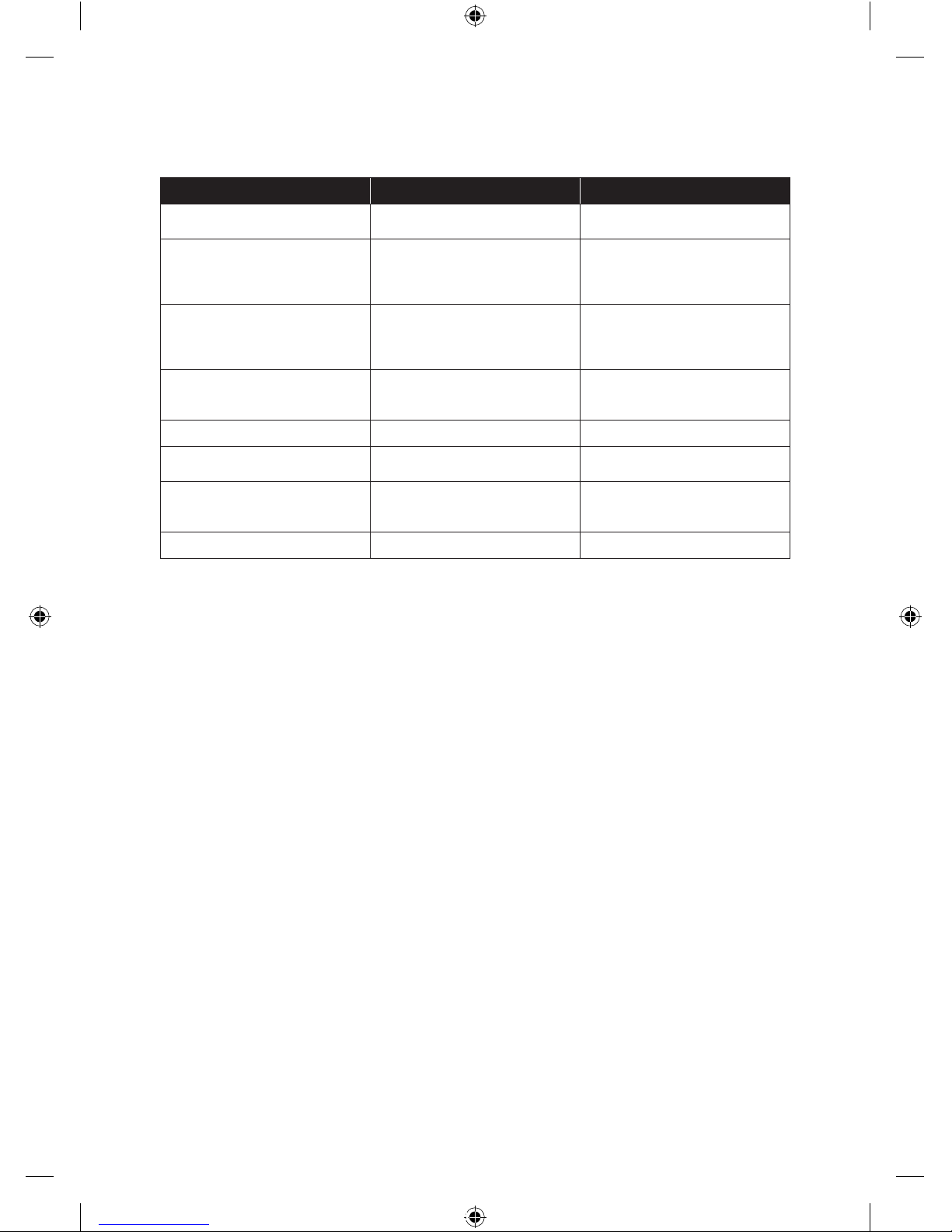
the clearances shall not be less than those shown in the table following.
Minimum clearances from power lines for electric animal fences
Power line Voltage V Clearance m
Less than or equal to 1 000 3
Greater than 1 000 and less than or equal to 33 000 4
Greater than 33 000 8
• If connecting leads and electric animal fence wires are installed near an overhead power
line, their height above the ground shall not exceed 3 m. This height applies either side of the
orthogonal projection of the outermost conductors of the power line on the ground surface, for
a distance of:
- 2 m for power lines operating at a nominal voltage not exceeding 1 000 V;
- 15 m for power lines operating at a nominal voltage exceeding 1 000 V.
• Electric animal fences intended for deterring birds, household pet containment or training
animals such as cows need only be supplied from low output energizers to obtain satisfactory
and safe performance.
• In electric animal fences intended for deterring birds from roosting on buildings, no electric
fence wire shall be connected to the energizer earth electrode. A warning sign shall be tted to
every point where persons may gain ready access to the conductors.
• Fence wiring should be installed well away from any telephone or telegraph line or radio aerial.
• Where an electric animal fence crosses a public pathway, a non-electried gate shall be
incorporated in the electric animal fence at that point or a crossing by means of stiles shall be
provided. At any such crossing, the adjacent electried wires shall carry warning signs.
10
700034011_230V_M40-M40D-M65-M65D-Smart M SerieA+D_A5.indd 10 03-05-16 15:50
• Any part of an electric animal fence that is installed along a public road or pathway shall
be identied by electric fence warning signs (4002555) at regular intervals that are securely
fastened to the fence posts or rmly clamped to the fence wires.
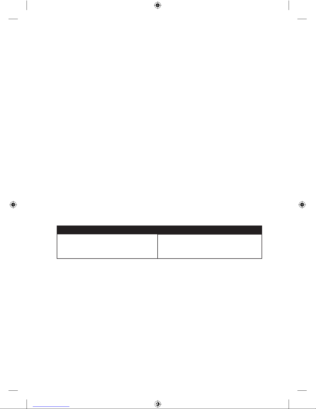
• The size of the warning sign shall be at least 100mm x 200mm.
• The background colour of both sides of the warning sign shall be yellow. The inscription on the
sign shall be black and shall be either:
- the substance of “CAUTION: Electric Animal Fence” or,
- the symbol shown:
• The inscription shall be indelible, inscribed on both sides of the warning sign and have a height
of at least 25mm.
• Ensure that all mains operated, ancillary equipment connected to the electric animal fence
circuit provides a degree of isolation between the fence circuit and the supply mains equivalent
to that provided by the energizer.
• Protection from the weather shall be provided for the ancillary equipment unless this equipment
is certied by the manufacturer as being suitable for use outdoors, and is of a type with a
minimum degree of protection IPX4.
This energizer complies with international safety regulations and is manufactured to international
standards.
Elephant reserves the right to make changes without notice to any product specication to
improve reliability, function or design. E & OE.
The author thanks the International Electrotechnical Commission (IEC) for permission to
reproduce Information from its International Publication 60335-2-76 ed.2.0 (2002). All such
extracts are copyright of IEC, Geneva, Switzerland. All rights reserved. Further information on
the IEC is available from www.iec.ch. IEC has no responsibility for the placement and context in
which the extracts and contents are reproduced by the author, nor is IEC in any way responsible
for the other content or accuracy therein.
Service of double-insulated appliances
In a double-insulated controller, two systems of insulation are provided instead of grounding.
No equipment grounding means is provided in the supply cord of a double-insulated
controller, nor should a means for equipment grounding be added to the controller. Servicing
a double-insulated controller requires extreme care and knowledge of the system, and
should be done only by qualied service personnel. Replacement parts of a double insulated
controller must be identical to the parts they replace. A double insulated controller is marked
with the words “DOUBLE INSULATION” or “DOUBLE INSULATED”. The symbol for double
insulation may also be marked on the appliance.
11
700034011_230V_M40-M40D-M65-M65D-Smart M SerieA+D_A5.indd 11 03-05-16 15:50

Elephant M40, M40D, M65, M65-D,
Elephant SMART M Serie A+D
Inhaltsverzeichnis:
1 Einleitung 13
2 Montage des Weidezaungeräts 14
2.1 Allgemein 14
2.2 Wandmontage 14
3 Erklärung der Symbole und des Displays 14
3.1 Anschlusssymbole auf allen Modellen 14
3.2 Elephant M40 15
3.2 Elephant M40-D, M65, M65-D 15
3.3 Elephant SMART M Serie A+D 15
4 Elephant SMART A+D TIME DELAY und POWERMODUS 16
4.1 Elephant SMART allgemein 16
4.2 Signale bei aktiviertem TIME DELAY und POWERMODUS 16
5 Anschluss der Erdung 16
5.1 Anschluss der Erdung allgemein 16
5.2. Einsetzen des Erdstabs 16
5.3. Montage des Erdkabels 16
5.4. Testen der Erdung 17
6 Anschluss des Zauns 17
6.1 Montage des Zaunkabels - Volle Leistung 17
6.2 Montage des Zaunkabels - Halbe Leistung 17
7 Problemlösung 18
8 Praktische Tipps 18
9 Garantie 19
10 Wichtige Informationen 19
12
D
Montageanleitung
700034011_230V_M40-M40D-M65-M65D-Smart M SerieA+D_A5.indd 12 03-05-16 15:50
13
1 Einleitung
Herzlichen Glückwunsch – Sie sind nun Besitzer eines Elephant Qualitätsweidezaungerätes.
Damit Sie viele Jahre Freude an Ihrem Elephant Weidezaungerät haben, ist es wichtig, dem
Produkt die optimalen Bedingungen zu bieten.
Wenn das Gerät in Betrieb ist, kann es sowohl in Räumen als auch im Freien betrieben
und problemlos schlechten Wetterverhältnissen mit starkem Niederschlag und hohen
Temperaturschwankungen ausgesetzt werden. Das ist darauf zurückzuführen, dass die
“eigene” Aufheizung aus dem bescheidenen Stromverbrauch des Geräts genügt, um die
Elektronik frei von Feuchtigkeit zu halten.
Wenn das Gerät nicht in Betrieb ist, sollte es in einem Raum mit konstanten
Temperaturverhältnissen aufbewahrt werden.
Sie dürfen den Weidezaungerät also nicht über längere Zeit ohne Strom im Freien hängen
lassen, da Feuchtigkeit und Kondensat sehr schnell (vor allem in der Winterzeit) die
Leiterplatten und Elektronikkomponenten zersetzen, und dadurch den Weidezaungerät
beschädigen.
Um Ihren Weidezaungerät zusätzlich gegen Wind und Wetter zu schützen, dürfen Sie den
Weidezaungerät auch nicht mit bspw. einem Plastikbeutel abdecken, da der Weidezaungerät
dann nicht atmen kann. In vielen Fällen entsteht dadurch Feuchtigkeit, die zur Zersetzung der
Elektronikkomponenten des Weidezaungerätes innerhalb kürzester Zeit führt (2-6 Monate).
Batteriezäune und mobile Zäune, die an Batterien (mit Säuregehalt) angeschlossen werden,
müssen so geschützt werden, dass die Dämpfe der Batterie nicht mit der Elektronik des
Weidezaungerätes in Berührung kommen.
Sofern der Zaun aufgrund oben Genanntem beschädigt wird, entfällt der Garantie anspruch.
Prüfen Sie Ihre örtlichen Bestimmungen zu Umzäunungen: U. U. benötigen Sie vor dem
Gebrauch eine Genehmigung.
700034011_230V_M40-M40D-M65-M65D-Smart M SerieA+D_A5.indd 13 03-05-16 15:50
14
2 Montage des Weidezaungeräts
2.1 Algemein
Bevor Sie den Zaun montieren, ist es sehr wichtig diese Montageanleitung zu lesen. Ihr
Elektrozaun kann nur bei korrekter Montage voll genutzt werden. Es ist besonders wichtig, dass
die Erdverbindung, die Verbindung zum Zaun und die Zusammenfügung des Zaunes stimmen.
Das Elektrozaungerät sendet ca. jede Sekunde einen elektrischen Impuls durch den Zaun.
Diese Impulse versetzen dem Tier einen kurzen, scharfen, aber ungefährlichen Stromschlag,
der das Tier nicht gefährdet, aber ausreicht, ständig im Gedächtnis zu bleiben, so dass es
den Zaun meidet.
Befestigen Sie das Weidezaungerät an einer Mauer oder Wand, geschützt vor direkten
Witterungseinüssen. Das Weidezaungerät für Kinder unzugänglich halten. Stellen Sie
bei der Installation des Weidezaungeräts sicher, dass Brandgefahr und jedes Risiko auf
mechanischen Schaden ausgeschlossen sind. Das Weidezaungerät nicht in der Nähe
elektrischer Geräte, wie Elektropumpen, schwere Elektromotoren, Strommasten und andere
Objekte, die eine elektrische Störung verursachen können, anbringen.
2.2 Wandmontage
a) Die Stelle zur Montage des Weidezaungeräts festlegen, dann im Abstand von 260 mm
(vertikal) zwei Löcher mit einem Durchmesser von 6 mm in die Wand bohren.
b) Die mitgelieferten Dübel in die Wand drücken und eine der beiden mitgelieferten
Schrauben in den obersten Dübel eindrehen, bis die Schraube noch etwa 10 mm aus der
Wand herausragt.
c) Das Weidezaungerät mit der oberen Montageöffnung an die Schraube hängen.
d) Dann die zweite Schraube durch die untere Montageöffnung hindurch handfest in den
Dübel eindrehen.
3 Erklärung der Symbole und des Displays
3.1 Anschlusssymbole auf allen Modellen
6mm
10mm
260mm
A B C D
Das Leitungsnetz kann an jede gängige
230V Steckdose angeschlossen werden.
Erdklemme, muss mit mindestens einem
Rohrerder verbunden werden.
Zaunanschluß, reduzierte Spannung.
Zurr Einzäunung sensibler Tiere.
Zaunanschluß (stark). Für Anwendung
bei normalen Verhältnissen.
700034011_230V_M40-M40D-M65-M65D-Smart M SerieA+D_A5.indd 14 03-05-16 15:50

15
3.2 Elephant M40
3.3 Elephant M40-D, M65, M65-D
3.4 Elephant SMART M Serie A+D
*Siehe 4.2 für eine Erläuterung
der POWERMODUS Einstellungen.
Blinkt periodisch, wenn der Elektrozaun
eingeschaltet ist.
M40. Diese blinkt, wenn die Zaun-
spannung über 2000 Volt ist.
Blinkt periodisch, wenn der Elektrozaun
eingeschaltet ist.
Leuchtet bei jedem Impuls kurz rot auf.
M65, Spannungsanzeige, 4 LED-
Lämpchen, (je 1000 Volt) 1000V, 2000V,
3000V und 4000Volt.
M40D, M65D, Spannung wird in kV auf
dem Display angezeigt.
Die Grüne LED-Lampe leuchtet, das
Gerät ist eingeschaltet.
Rote LED-Lampe leuchtet, Alarm / TIME
DELAY ist eingeschaltet. (Summton
ertönt)
Spannungsanzeige, in 5 Schritten von
2kV (2kV, 4kV, 6kV, 8kV und 10kV)
Digitales Display zeigt 5 Stromimpulse
lang die Ausgangsspannung in kV an,
anschließend wird 1 Stromimpuls lang
die gewählte Modus-Einstellung des
Geräts angezeigt:
05 Modus, Standardmodus 5 Joule
08 Modus, POWERMODUS 08 Joule
15 Modus, POWERMODUS, 15 joule
700034011_230V_M40-M40D-M65-M65D-Smart M SerieA+D_A5.indd 15 03-05-16 15:50

16
4 Elephant SMART A+D TIME DELAY und POWERMODUS
4.1 Elephant SMART allgemein
Die Weidezaungeräte der Elephant SMART Serie (A+D) verfügen alle über die Funktion TIME
DELAY und POWERMODUS. Diese Geräte überwachen kontinuierlich die Leistungen Ihres
Zauns und reagieren auf Veränderungen im Zaun. Bei einem plötzlichen Spannungsabfall am
Zaun schaltet das Elephant SMART automatisch auf TIME DELAY Modus um und steigert
anschließend die Leistung.
4.2 Signale bei aktiviertem TIME DELAY und POWERMODUS
Bei aktiviertem TIME DELAY leuchtet
• die rote Alarm LED-Leuchte auf,
• es erklingt ein regelmäßiger Summton (Buzzer),
• und die normale Impulsdauer von 1,3 Sekunden wird auf 1 Impuls alle 3 Sekunden verlangsamt.
• der POWERMODUS wird eingeschaltet
Der TIME DELAY Modus bleibt ca. 9 Minuten eingeschaltet, danach erlöschen alle Signale
(Alarme) und die Zeit zwischen zwei Impulsen wird wieder auf den normalen Intervall von
1,3Sekunden umgeschaltet. Der POWERMODUS, der notwendig ist, um eine möglichst hohe
Spannung auf dem Zaun zu erhalten, bleibt eingeschaltet.
Erklärung zu den POWERMODUS Einstellungen,
• 05, Normaler Modus, das Weidezaungerät funktioniert im normalen 5 Joule Modus.
• 08, POWERMODUS, das Gerät erzeugt maximal 8 Joule an Energie.
• 15, POWERMODUS, das Gerät erzeugt maximal 15 Joule an Energie.
5 Anschluss der Erdung
5.1 Anschluss der Erdung allgemein
Für den Anschluss der Erdung sollten unbedingt verzinkte Materialien verwendet werden,
da diese eine gute Verbindung gewährleisten. Andere Materialien können oxidieren. Durch
schlechteKontakte kann das System nicht richtig funktionieren und können Störungen
verursacht werden. Die Anweisungen für die Erdung müssen sorgfältig eingehalten werden!
Wichtig! Sorgen Sie dafür, dass die Erdstäbe mit Zwischenräumen von mindestens 4 Metern
eingesetzt werden und mindestens 10 Meter von eventuell vorhandener elektrischer Bekabelung
entfernt sind. Eine schlechte Erdung kann zu funktechnischen Störungen an Telefon-, Radiound TV-Leitungen führen. Dies zeigt sich beispielsweise an Klick-Geräuschen während
Telefongesprächen.
5.2 Einsetzen des Erdstabs
Setzen Sie mindestens einen verzinkten Erdstab von 1 m Länge (SMART M Serie A+D
mindestens 2 von 2 m Länge) (Art.Nr. 055853) in den möglichst feuchten Boden. Bei trockenem
Erdreich oder in Regionen mit einem geringen Mineralstoffgehalt im Boden sind häug mehrere
Erdstäbe notwendig!
Erdstäbe müssen im Abstand von mindestens 4 m und in mindestens 10 m Entfernung zu
Strom- oder Telefonkabeln, Wasserleitungen oder Gebäudeerdung eingesetzt werden.
VerbindenSie Erdkabel keinesfalls mit Metallteilen eines Gebäudes.
5.3 Montage des Erdkabels
a) Verwenden Sie hierfür *1,6mm2 oder 2,5mm isoliertes Erdkabel. Entfernen Sie am einen Ende
des Erdkabels ca. 2 cm des Kunststoffmantels und verbinden Sie dieses Ende mit der linken
blauen Anschlussbefestigung unter dem Symbol des Weidezaungeräts. Drehen Sie den
Knopf der Anschlussbefestigung, bis der Draht stabil festgeklemmt ist.
b) Entfernen Sie am anderen Ende des Erdkabels ca. 10 cm des Kunststoffmantels und
verbinden Sie das freigelegte Drahtende dann über eine Erdungsklemme mit dem Erdstab.
Ziehen Sie die Klemme fest an.
700034011_230V_M40-M40D-M65-M65D-Smart M SerieA+D_A5.indd 16 03-05-16 15:50
 Loading...