

Page 1

EXPRESS - User Manual
MULTIFUNCTION ELECTRICAL PANEL FROM 1 TO 4 MOTORS
Page 2

Page 3

III
CONTENTS
1. INTRODUCTION ...................................................................................................... 5
2. WARNINGS ............................................................................................................ 6
3. INSTALLATION ........................................................................................................ 7
4. INDICATIONS LIGHT AND CONTROLS ..................................................................... 8
4.1 Main display items ........................................................................................................... 8
4.2 Activation of load in manual mode ................................................................................ 10
5. MOTHERBOARD INPUTS AND OUTPUTS .............................................................. 11
6. EXTENSION INPUTS AND OUTPUTS ...................................................................... 12
7. FUNCTIONS AND SETTINGS .................................................................................. 13
7.1 FUNCTION 1 - Draining with floats/pressure switches ................................................... 13
7.2 FUNCTION 2 - Draining with level sensors and floats/pressure switches ....................... 15
7.3 FUNCTION 3 - Drainage with “COS-PHI” power factor .................................................. 17
7.4 FUNCTION 4 - Control with analogue signal and floats/pressure switches ................... 20
7.5 FUNCTION 5 - Control with analogue signal and level sensors ...................................... 22
7.6 FUNCTION 6 - Control with analogue signal and “COS-PHI” power factor .................... 24
7.7 FUNCTION 7 - Filling with level sensors and floats/pressure switches ........................... 27
7.8 FUNCTION 8 - Filling with level sensors and “COS-PHI” power factor ............................ 29
8. ALARMS ............................................................................................................... 32
9. GENERAL CONDITIONS ......................................................................................... 34
9.1 Warranty ....................................................................................................................... 34
9.2 Maintenance .................................................................................................................. 34
9.3 Disposal ......................................................................................................................... 34
10. DECLARATION OF CONFORMITY ...................................................................... 35
Page 4

IV
Page 5

5
1. INTRODUCTION
This manual must always accompany the relevant equipment and be conserved in an accessible
location for consultation by qualified technicians assigned for operation and maintenance of the
system.
The installer/user is strongly recommended to carefully read all instructions and information in this
manual before using the product, in order to avoid damage or improper use of the unit, which
would also render the warranty null and void.
Before operating the equipment, carefully read the manual and follow all instructions provided.
The information and instructions in this manual refer to the standard use of this product; in the
event of special circumstances, functions or applications not described in this document, contact our
service center for assistance.
If technical assistance or spare parts are required, when contacting the manufacturer always specify
the identification code of the model and construction number as stated on the data plate.
Our service center is available for any requirement or clarification.
On receipt of the goods, inspect immediately to ensure that the equipment has not been damaged
during transport. If defects are found, the client should promptly notify our retailer within 5 days of
receiving the goods, or in the event of direct purchases, the Elentek service center.
N.B. the information provided in this manual is subject to modifications without
notice. The manufacturer shall not be held liable for any damage caused in relation
to the use of these instructions, as they are to be considered guideline only. Note
that failure to observe the instructions provided in this manual may cause physical
injury or damage to objects.
In any event all local and/or current legislation must be observed at all times.
Page 6

6
2. WARNINGS
The electrical panel must be used exclusively for the purpose and function as specified in design.
Any other application or use is to be considered improper and therefore hazardous.
In the event of a fire in the place of installation or the surrounding area, avoid the use of water jets
and use the appropriate extinguishing equipment and means (powder, foam, carbon dioxide).
Install the equipment far from heat sources and in a dry and sheltered location in observance of the
stated protection rating (IP).
The installation of a safety device is recommended to protect the panel power line in compliance
with current electrical standards.
The electrical panel must be connected by a qualified electrician in observance of the relevant
electrical standards.
No parts of the panel must be disassembled without the official authorization of Elentek: any
tampering with or modifications to the unit will render all terms of the warranty null and void.
All installation and/or maintenance operations must be performed by a specialized technician who is
fully aware of the relevant current safety standards.
Ensure the installation is connected to an efficient earthing system.
After making the electrical connection, check that all electrical panel settings are correct to avoid
automatic start-up of the electric pump.
Elentek declines all liability in the event of the following:
- Incorrect installation;
- Use by personnel not adequately trained in the correct use of the panel;
- Serious failure to perform scheduled maintenance;
- Use of non-original spare parts or parts not specific to the model;
- Unauthorized modifications or interventions;
- Partial or total failure to observe instructions.
Page 7

7
3. INSTALLATION
Ensure that the mains power supply specifications correspond to the voltage specified on the data
plate of the electrical panel and motor connected, then make the earthing connection before all
other connections.
The power line must be protected by a residual current circuit breaker.
Tighten the electrical cables on the relative terminals using a suitable tool correctly sized to avoid
the risk of damage to the fixing screws. Take care if using an electric screwdriver.
The electrical panel is designed for wall-mounting using screws and plugs in the pre-drilled holes at
the corners of the enclosure, or by means of brackets when present.
Install the equipment in areas compliant with the protection rating and ensure that the box is kept
intact when drilling the holes for fitting the cable clamps.
Avoid the use of multicore cables where there are wires connected to inductive loads and power
cables and signal cables such as sensors and digital inputs.
Keep connection cables as short as possible, preventing any twisting of cables, which may be
harmful due to inductive effects on the electronic equipment.
All wires used in the cabling must be suitably sized to withstand the load to be powered.
Page 8
8
4. INDICATIONS LIGHT AND CONTROLS
4.1 Main display items
The EXPRESS electrical panel has been designed for settable protection of 1 to 4 motors with the
option of selecting the operating mode according to the specific system used.
Among the various modes, the panel enable motor control by means of:
- pressure switches;
- floats;
- remote contacts;
- start/stop floats;
- level sensors;
- 0-10V signals;
- 4-20mA pressure transducers;
- “COS-PHI” power factor (where “Phi” is the timing angle between current and voltage).
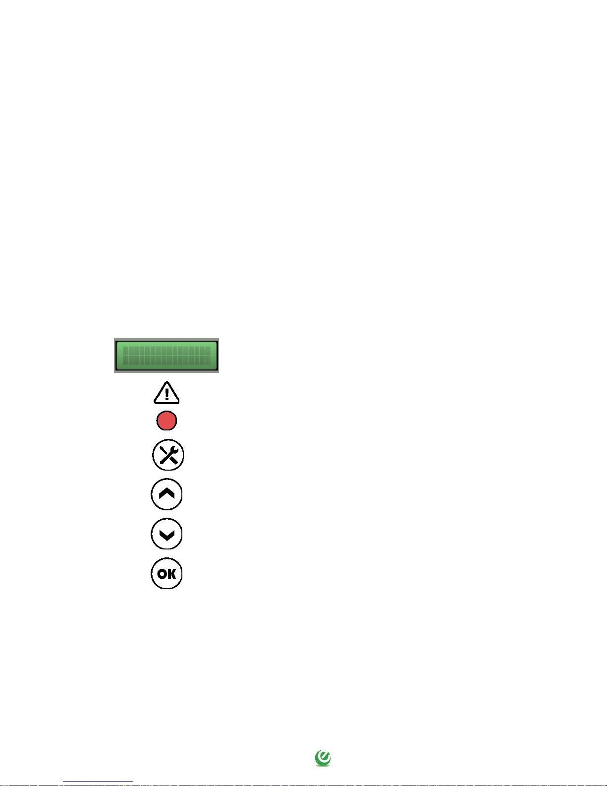
Display of values and programming
Red led: general alarm
SETUP (or multifunction) button
UP arrow button
DOWN arrow button
OK button
EXPRESS
V. 1.0i
Page 9
9
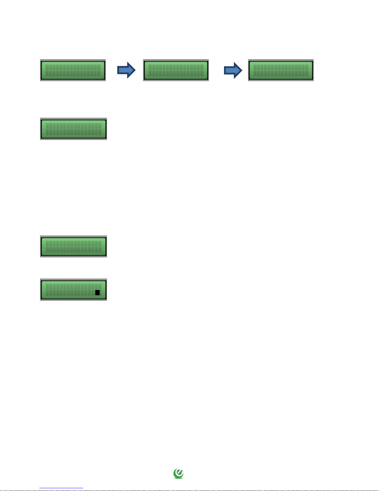
On activation of the panel, the display shows the following:
At the end of the start-up sequence, the main menu is displayed, as described below.
MAIN SCREEN: This screen enables the display of active motors, voltage on
input and total absorption of the panel:
230 V = Power supply voltage reading;
7.0 Atot = Total current absorbed by the panel;
P1 ( 0 ) = Motor 1 deactivated; P1 ( 1 ) = Motor 1 active;
P2 ( 0 ) = Motor 2 deactivated; P2 ( 1 ) = Motor 2 active;
P3 ( 0 ) = Motor 3 deactivated; P3 ( 1 ) = Motor 3 active;
If operating modes are used with analogue signals, the main screen also
displays the input signal expressed as a percentage, in metres or bar.
MOTOR SCREEN: By pressing SETUP the user can view the screen of each
motor (P1, P2 and P3), where the following is displayed:
230 V = Power supply voltage reading;
0.0 A = Current absorbed by connected load;
1.0 ϕ = Power factor of connected load;
MAN () = Panel set to manual mode;
AUT () = Panel set to automatic mode;
MAN ( ) AUT ( ) = Panel on standby;
P1 0 = Motor 1 deactivated;
P1 1 = Motor 1 active;
EXPRESS
V. 1.0i
E L E N T E K
www.elentek.com
MODEL 50Hz
SINGLE PHASE
230V 7.0A tot
P1 (1) P2 (1) P3 (0)
230V 7.0At 1.0b
230V 0.0A 1.0@
MAN ( ) AUT (*) P1 1
Page 10

10
4.2 Activation of load in manual mode
On start-up, the panel starts in automatic mode, as confirmed by the asterisk () displayed
alongside the text AUT on the display of each motor, or according to the previous status set before
shutdown.
The operating mode can be changed by pressing the UP arrow to change to Manual mode, or the
DOWN arrow to change to Automatic mode.
Therefore, to enable operation in Manual mode, press the UP arrow (the asterisk () is displayed
alongside the text MAN) and then press and hold OK.
The display then displays current absorption of the motor and the cos-phi power factor values in real
time.
On release of the OK button, the motor is shut down.
N.B. in manual mode, the load is activated and bypasses all alarms, but in the event
of a faulty the display flashes.
Page 11

11
5. MOTHERBOARD INPUTS AND OUTPUTS
I1 - C
Normally open input for motor klicson (thermal protection on motor
temperature overload).
SH - C - C - SL
General enabling input for:
- Unipolar level probes;
- Minimum level float (connection between SH/SL and C).
N.B.: CHECK THE CONNECTION DIAGRAM BASED ON THE SELECTED
OPERATING LOGIC.
A - B
Multi-function digital/analogue input:
- Normally open input for motor activation from pressure switch or
operating float;
- Analogue 4-20 mA input (terminal A = positive / terminal B = negative);
- Analogue 0-10 V input (terminal A = negative / terminal B = positive).
N.B.: CHECK THE CONNECTION DIAGRAM BASED ON THE SELECTED
OPERATING LOGIC.
I2 - C
Normally open input for alarm activation.
OUT ALARM
(NC - C - NA)
Cumulative alarm output with voltage-free alarm contacts (resistive load
5A - 250V) for:
- Motor alarm ... dry running.
- Motor alarm ... protection.
- Motor alarm ... thermal overload.
- Low voltage alarm.
- Overvoltage alarm.
- Sequence or no-phase alarm.
- Max. level alarm.
- Motor alarm ... communication.
- Min. level alarm.
OUT MOTOR
SINGLE-PHASE:
L/S – Motor phase
N/R – Motor neutral
AVV – Start-up with on board capacitor
THREE-PHASE:
T1 (contactor) – Motor U phase
T2 (contactor) – Motor V phase
T3 (contactor) – Motor W phase
Earth.
Page 12

12
6. EXTENSION INPUTS AND OUTPUTS
I2 - C
Normally open input for motor klicson (thermal protection on motor
temperature overload).
I1 - C
Normally open input for motor activation from pressure switch or
operating float.
N.B.: CHECK THE CONNECTION DIAGRAM BASED ON THE SELECTED
OPERATING LOGIC.
OUT MOTOR
SINGLE-PHASE:
L/S – Motor phase
N/R – Motor neutral
AVV – Start-up with on-board capacitor
THREE PHASE:
T1 (contactor) – Motor U phase
T2 (contactor) – Motor V phase
T3 (contactor) – Motor W phase
Earth.
Page 13

13
7. FUNCTIONS AND SETTINGS
The EXPRESS panel features a host of internal functions.
There are basically 8 operating modes developed for various types of application as described
below.
7.1 FUNCTION 1 - Draining with floats/pressure switches
This operating mode is used for drainage applications using floats or pressure switches, enabling the
control of one or more pumps.
On selection of mode 1, all relative parameter fields for this function are enabled.
7.1.1 Programming menu
To select the panel operating logic, access the programming menu by pressing the buttons SETUP,
UP and DOWN at the same time on the main screen of the panel.
DESCRIPTION OF PARAMETER
VALUE
LANGUAGE
0=ITA / 1=ENG / 2=FRA / 3=ESP / 4=GER
0 - 4
WORKING MODE SETTING
1
NUMBER OF PUMPS
This parameter enables selection of the number of pumps in the system (when 1 single
pump is selected, the parameters PUMP ROTATION ENABLED
and FLOAT START/STOP FUNCTION are disabled. For the START / STOP to 1 single pump
attach the float start between C-SH and the float stop between C-SL).
1 - 4
PUMP ROTATION ENABLED
This parameter enables activation of pump exchange on each demand from floats or
pressure switches. Also, if the main pump thermal cutout (current overload) trips, the
second pump is enabled (if set to N, parameter START/STOP is disabled).
Y or N
FLOAT START/STOP FUNCTION (self-holding).
This parameter enables deactivation of active pumps only on opening of the G.MIN.
contact (min. level/stop float). This function is only available when pump rotation is
enabled.
Y or N
MINIMUM LEVEL ALARM OUTPUT
This parameter enables removal of the minimum level alarm from the cumulative alarm
output.
Y or N
Page 14

14
7.1.2 User menu
On completion of panel operation programming, enter the setup menu to configure the various data
for motor start-up.
To access the user menu, press the button SETUP for 4 seconds in the main screen of the panel.
DESCRIPTION OF PARAMETER
VALUE
MINIMUM VOLTAGE
Set by default at -10% .
Modifications to operating limits beyond the default parameters will immediately render
the warranty null and void.
207 (230)
360 (400)
MAXIMUM VOLTAGE
Set by default at +10% .
Modifications to operating limits beyond the default parameters will immediately render
the warranty null and void.
253 (230)
440 (400)
MAXIMUM CURRENT P1 / P2 / P3 / P4
This parameter enables entry of the maximum current for each motor.
Enter the maximum current value, increasing it by 10-15% with respect to the rated
motor value.
Modifications to operating limits beyond the parameters stated on the model data plate
will immediately render the warranty null and void.
1 - … A
DISPLAY BRIGHTNESS ON STANDBY
This parameter enables entry of the brightness setting applied when the display sets to
standby (wait 9 seconds for a preview).
0 - 9
TIME FOR ENTRY TO SET-UP
This parameter enables entry of the time to keep the SETUP button pressed for access to
the set-up menu.
2 - 30 Sec
Page 15

15
7.2 FUNCTION 2 - Draining with level sensors and floats/pressure switches
This operating mode is used for drainage applications using level sensors and floats or pressure
switches, enabling the control of one or more pumps.
On selection of mode 2, all relative parameter fields for this function are enabled.
7.2.1 Programming menu
To select the panel operating logic, access the programming menu by pressing the buttons SETUP,
UP and DOWN at the same time on the main screen of the panel.
DESCRIPTION OF PARAMETER
VALUE
LANGUAGE
0=ITA / 1=ENG / 2=FRA / 3=ESP / 4=TED
0 - 4
WORKING MODE SETTING
2
NUMBER OF PUMPS
This parameter enables selection of the number of pumps in the system (when 1 single
pump is selected, the parameter PUMP ROTATION ENABLED is disabled).
1 - 4
PUMP ROTATION ENABLED
This parameter enables activation of pump exchange on each demand from floats or
pressure switches. Also, if the main pump thermal cutout (current overload) trips, the
second pump is enabled.
Y or N
MINIMUM LEVEL ALARM OUTPUT
This parameter enables removal of the minimum level alarm from the cumulative alarm
output.
Y or N
SENSOR SENSITIVITY (Sa - Sb - Sc - Sd)
This parameter enables display of sensor sensitivity. If with the contacts open a value of
99 is displayed, and if a value of 55 is displayed with water present, set sensitivity to an
intermediate value, such as 75.
55 - 99
Page 16

16
7.2.2 User menu
On completion of panel operation programming, enter the setup menu to configure the various data
for motor start-up.
To access the user menu, press the button SETUP for 4 seconds in the main screen of the panel.
DESCRIPTION OF PARAMETER
VALUE
MINIMUM VOLTAGE
Set by default at -10% .
Modifications to operating limits beyond the default parameters will immediately render
the warranty null and void.
207 (230)
360 (400)
MAXIMUM VOLTAGE
Set by default at +10% .
Modifications to operating limits beyond the default parameters will immediately render
the warranty null and void.
253 (230)
440 (400)
MAXIMUM CURRENT P1 / P2 / P3 / P4
This parameter enables entry of the maximum current for each motor.
Enter the maximum current value, increasing it by 10-15% with respect to the rated motor
value.
Modifications to operating limits beyond the parameters stated on the model data plate
will immediately render the warranty null and void.
1 - … A
DISPLAY BRIGHTNESS ON STANDBY
This parameter enables entry of the brightness setting applied when the display sets to
standby (wait 9 seconds for a preview).
0 - 9
TIME FOR ENTRY TO SET-UP
This parameter enables entry of the time to keep the SETUP button pressed for access to
the set-up menu.
2 - 30 Sec
Page 17

17
7.3 FUNCTION 3 - Drainage with “COS-PHI” power factor
This operating mode is used for drainage applications with dry running safety control, obtained from
the power factor (where “Phi” is the timing angle between current and voltage), without the need
for external commands (float or pressure switch), enabling the control of one or more pumps.
On selection of mode 3, all relative parameter fields for this function are enabled.
7.3.1 Programming menu
To select the panel operating logic, access the programming menu by pressing the buttons SETUP,
UP and DOWN at the same time on the main screen of the panel.
DESCRIPTION OF PARAMETER
VALUE
LANGUAGE
0=ITA / 1=ENG / 2=FRA / 3=ESP / 4=GER
0 - 4
WORKING MODE SETTING
3
NUMBER OF PUMPS
This parameter enables selection of the number of pumps in the system (when 1 single
pump is selected, the parameter PUMP ROTATION ENABLED is disabled).
1 - 4
PUMP ROTATION ENABLED
This parameter enables activation of pump exchange on each demand from floats or
pressure switches. Also, if the main pump thermal cutout (current overload) trips, the
second pump is enabled.
Y or N
MINIMUM LEVEL ALARM OUTPUT
This parameter enables removal of the minimum level alarm from the cumulative alarm
output.
Y or N
COS-PHI ALARM OUTPUT
This parameter allows enabling and disabling switching of the output relay for freevoltage contact alarms on dry running.
Y or N
Page 18

18
7.3.2 User menu
On completion of panel operation programming, enter the setup menu to configure the various data
for motor start-up.
To access the user menu, press the button SETUP for 4 seconds in the main screen of the panel.
DESCRIPTION OF PARAMETER
VALUE
MINIMUM VOLTAGE
Set by default at -10% .
Modifications to operating limits beyond the default parameters will immediately render
the warranty null and void.
207 (230)
360 (400)
MAXIMUM VOLTAGE
Set by default at +10% .
Modifications to operating limits beyond the default parameters will immediately render
the warranty null and void.
253 (230)
440 (400)
MAXIMUM CURRENT P1 / P2 / P3 / P4
This parameter enables entry of the maximum current for each motor.
Enter the maximum current value, increasing it by 10-15% with respect to the rated
motor value.
Modifications to operating limits beyond the parameters stated on the model data plate
will immediately render the warranty null and void.
1 - … A
MINIMUM COS-PHI P1 / P2 / P3 / P4
This parameter establishes the minimum Cos-Phi power factor value for each motor
Enable operation in manual mode, activate in no-load conditions (dry running), check
the power factor reading (e.g. 0.65) and enter the minimum power factor, increasing it
by approx. 0.05.
0.15 - 1.00
AUTOMATIC RESET ON DRY RUNNING ALARM
In the event of a dry running alarm (minimum power factor) the panel may attempt to
reset automatically, which can be programmable in minutes.
4 reset times can be set, in which the system automatically restarts after being blocked.
By default these values are set as shown below:
The first reset attempt is performed 1 minute after the dry running alarm.
The second reset attempt is performed 2 minutes after the alarm.
The third reset attempt is performed 3 minutes after the alarm.
The fourth reset attempt is performed 4 minutes after the alarm.
1 - 240 Min
Page 19

19
DESCRIPTION OF PARAMETER
VALUE
SEQUENTIAL RESET ON DRY RUNNING ALARM
If the value is set to N, all automatic resets are blocked after the fourth attempt; if the
value is set to S (Yes) at the end of the fourth attempt, the reset cycle is repeated
continuously.
The system protecting the panel against dry running conditions activates the reset cycle
according to the time intervals set, and resumes the same reset cycle each time water is
detected for more than 10 seconds.
Y or N
DISPLAY BRIGHTNESS ON STANDBY
This parameter enables entry of the brightness setting applied when the display sets to
standby (wait 9 seconds for a preview).
0 - 9
TIME FOR ENTRY TO SET-UP
This parameter enables entry of the time to keep the SETUP button pressed for access to
the set-up menu.
2 - 30 Sec
Page 20

20
7.4 FUNCTION 4 - Control with analogue signal and floats/pressure switches
This operating mode is used for managed applications via analogue signals and floats or pressure
switches, enabling the control of one or more pumps.
On selection of mode 4, all relative parameter fields for this function are enabled.
7.4.1 Programming menu
To select the panel operating logic, access the programming menu by pressing the buttons SETUP,
UP and DOWN at the same time on the main screen of the panel.
DESCRIPTION OF PARAMETER
VALUE
LANGUAGE
0=ITA / 1=ENG / 2=FRA / 3=ESP / 4=GER
0 - 4
WORKING MODE SETTING
4
NUMBER OF PUMPS
This parameter enables selection of the number of pumps in the system (when 1 single
pump is selected, the parameter PUMP ROTATION ENABLED is disabled).
1 - 4
PUMP ROTATION ENABLED
This parameter enables activation of pump exchange on each demand from floats or
pressure switches. Also, if the main pump thermal cutout (current overload) trips, the
second pump is enabled.
Y or N
MINIMUM LEVEL ALARM OUTPUT
This parameter enables removal of the minimum level alarm from the cumulative alarm
output.
Y or N
TYPE OF ANALOGUE SIGNAL
This parameter enables selection of the type of analogue signal on input to the panel:
0 = 0-10 V (terminal A = positive / terminal B = negative)
1 = 4-20 mA (terminal A = negative / terminal B = positive)
0 or 1
UNIT OF MEASUREMENT
This parameter enables selection of the measurement unit of the analogue signal on
input to the panel.
“% +” and “bar” : system under refilling /pressurising;
“% -“ and “cm” : system under emptying
“%+” or “% -”
“cm” or “bar”
FULL SCALE OF ANALOGUE SIGNAL
This parameter enables selection of the full scale of the analogue signal on input to the
panel.
1.0 - 999.9
Page 21

21
7.4.2 User menu
On completion of panel operation programming, enter the setup menu to configure the various data
for motor start-up.
To access the user menu, press the button SETUP for 4 seconds in the main screen of the panel.
DESCRIPTION OF PARAMETER
VALUE
MINIMUM VOLTAGE
Set by default at -10% .
Modifications to operating limits beyond the default parameters will immediately render
the warranty null and void.
207 (230)
360 (400)
MAXIMUM VOLTAGE
Set by default at +10% .
Modifications to operating limits beyond the default parameters will immediately render
the warranty null and void.
253 (230)
440 (400)
MAXIMUM CURRENT P1 / P2 / P3 / P4
This parameter enables entry of the maximum current for each motor.
Enter the maximum current value, increasing it by 10-15% with respect to the rated
motor value.
Modifications to operating limits beyond the parameters stated on the model data plate
will immediately render the warranty null and void.
1 - … A
SET POINT
This parameter enables entry of the set point for pressure (bar), level (centimetres) or
percentage to be maintained on the system.
The maximum settable value depends on the “ANALOGUE SIGNAL FULL SCALE” set in the
ASSISTANCE menu.
0.0 - 999.9
THRESHOLD P1 / P2 / P3 / P4
In the case of threshold P1, this indicates the restart value of the first pump (master) on
decrease or increase of the previously entered set point.
In the case of threshold P2, P3 and P4, this indicates the start and stop values of the
pumps used as backup units.
The maximum settable value depends on the “ANALOGUE SIGNAL FULL SCALE” set in
the ASSISTANCE menu.
0.0 - 999.9
DISPLAY BRIGHTNESS ON STANDBY
This parameter enables entry of the brightness setting applied when the display sets to
standby (wait 9 seconds for a preview).
0 - 9
TIME FOR ENTRY TO SET-UP
This parameter enables entry of the time to keep the SETUP button pressed for access to
the set-up menu.
2 - 30 Sec
Page 22

22
7.5 FUNCTION 5 - Control with analogue signal and level sensors
This operating mode is used for managed applications via analogue signals and level sensors,
enabling the control of one or more pumps.
On selection of mode 5, all relative parameter fields for this function are enabled.
7.5.1 Programming menu
To select the panel operating logic, access the programming menu by pressing the buttons SETUP,
UP and DOWN at the same time on the main screen of the panel.
DESCRIPTION OF PARAMETER
VALUE
LANGUAGE
0=ITA / 1=ENG / 2=FRA / 3=ESP / 4=GER
0 - 4
WORKING MODE SETTING
5
NUMBER OF PUMPS
This parameter enables selection of the number of pumps in the system (when 1 single
pump is selected, the parameter PUMP ROTATION ENABLED is disabled).
1 - 4
PUMP ROTATION ENABLED
This parameter enables activation of pump exchange on each demand from floats or
pressure switches. Also, if the main pump thermal cutout (current overload) trips, the
second pump is enabled.
Y or N
MINIMUM LEVEL ALARM OUTPUT
This parameter enables removal of the minimum level alarm from the cumulative alarm
output.
Y or N
SENSOR SENSITIVITY (Sa - Sb - Sc - Sd)
This parameter enables display of sensor sensitivity. With the contacts open, if a value of
99 is displayed, and a value of 55 is displayed with water present, set sensitivity to an
intermediate value, such as 75.
55 - 99
TYPE OF ANALOGUE SIGNAL
This parameter enables selection of the type of analogue signal on input to the panel:
0 = 0-10 V (terminal A = positive / terminal B = negative)
1 = 4-20 mA (terminal A = negative / terminal B = positive)
0 or 1
UNIT OF MEASUREMENT
This parameter enables selection of the measurement unit of the analogue signal on
input to the panel.
“% +” and “bar” : system under refilling /pressurising;
“% -“ and “cm” : system under emptying
“%+” or “% -”
“cm” or “bar”
FULL SCALE OF ANALOGUE SIGNAL
This parameter enables selection of the full scale of the analogue signal on input to the
panel.
1.0 - 999.9
Page 23

23
7.5.2 User menu
On completion of panel operation programming, enter the setup menu to configure the various data
for motor start-up.
To access the user menu, press the button SETUP for 4 seconds in the main screen of the panel.
DESCRIPTION OF PARAMETER
VALUE
MINIMUM VOLTAGE
Set by default at -10% .
Modifications to operating limits beyond the default parameters will immediately render
the warranty null and void.
207 (230)
360 (400)
MAXIMUM VOLTAGE
Set by default at +10% .
Modifications to operating limits beyond the default parameters will immediately render
the warranty null and void.
253 (230)
440 (400)
MAXIMUM CURRENT P1 / P2 / P3 / P4
This parameter enables entry of the maximum current for each motor.
Enter the maximum current value, increasing it by 10-15% with respect to the rated
motor value.
Modifications to operating limits beyond the parameters stated on the model data plate
will immediately render the warranty null and void.
1 - … A
SET POINT
This parameter enables entry of the set point for pressure (bar), level (centimetres) or
percentage to be maintained on the system.
The maximum settable value depends on the “ANALOGUE SIGNAL FULL SCALE” set in the
ASSISTANCE menu.
0.0 - 999.9
THRESHOLD P1 / P2 / P3 / P4
In the case of threshold P1, this indicates the restart value of the first pump (master) on
decrease or increase of the previously entered set point.
In the case of threshold P2, P3 and P4, this indicates the start and stop values of the
pumps used as backup units.
The maximum settable value depends on the “ANALOGUE SIGNAL FULL SCALE” set in
the ASSISTANCE menu.
0.0 - 999.9
DISPLAY BRIGHTNESS ON STANDBY
This parameter enables entry of the brightness setting applied when the display sets to
standby (wait 9 seconds for a preview).
0 - 9
TIME FOR ENTRY TO SET-UP
This parameter enables entry of the time to keep the SETUP button pressed for access to
the set-up menu.
2 - 30 Sec
Page 24

24
7.6 FUNCTION 6 - Control with analogue signal and “COS-PHI” power factor
This operating mode is used for managed applications via analogue signals with dry running safety
control, obtained from the Cos-Phi power factor (where “Phi” is the timing angle between current
and voltage), without the need for external commands (float or pressure switch), enabling the
control of one or more pumps.
On selection of mode 6, all relative parameter fields for this function are enabled.
7.6.1 Programming menu
To select the panel operating logic, access the programming menu by pressing the buttons SETUP,
UP and DOWN at the same time on the main screen of the panel.
DESCRIPTION OF PARAMETER
VALUE
LANGUAGE
0=ITA / 1=ENG / 2=FRA / 3=ESP / 4=GER
0 - 4
WORKING MODE SETTING
6
NUMBER OF PUMPS
This parameter enables selection of the number of pumps in the system (when 1 single
pump is selected, the parameter PUMP ROTATION ENABLED is disabled).
1 - 4
PUMP ROTATION ENABLED
This parameter enables activation of pump exchange on each demand from floats or
pressure switches. Also, if the main pump thermal cutout (current overload) trips, the
second pump is enabled.
Y or N
MINIMUM LEVEL ALARM OUTPUT
This parameter enables removal of the minimum level alarm from the cumulative alarm
output.
Y or N
COS-PHI ALARM OUTPUT
This parameter allows enabling and disabling switching of the output relay for freevoltage contact alarms on dry running.
Y or N
TYPE OF ANALOGUE SIGNAL
This parameter enables selection of the type of analogue signal on input to the panel:
0 = 0-10 V (terminal A = positive / terminal B = negative)
1 = 4-20 mA (terminal A = negative / terminal B = positive)
0 or 1
UNIT OF MEASUREMENT
This parameter enables selection of the measurement unit of the analogue signal on
input to the panel.
“% +” and “bar” : system under refilling /pressurising;
“% -“ and “cm” : system under emptying
“%+” or “% -”
“cm” or “bar”
FULL SCALE OF ANALOGUE SIGNAL
This parameter enables selection of the full scale of the analogue signal on input to the
panel.
1.0 - 999.9
Page 25

25
7.6.2 User menu
On completion of panel operation programming, enter the setup menu to configure the various data
for motor start-up.
To access the user menu, press the button SETUP for 4 seconds in the main screen of the panel.
DESCRIPTION OF PARAMETER
VALUE
MINIMUM VOLTAGE
Set by default at -10% .
Modifications to operating limits beyond the default parameters will immediately render
the warranty null and void.
207 (230)
360 (400)
MAXIMUM VOLTAGE
Set by default at +10% .
Modifications to operating limits beyond the default parameters will immediately render
the warranty null and void.
253 (230)
440 (400)
MAXIMUM CURRENT P1 / P2 / P3 / P4
This parameter enables entry of the maximum current for each motor.
Enter the maximum current value, increasing it by 10-15% with respect to the rated
motor value.
Modifications to operating limits beyond the parameters stated on the model data plate
will immediately render the warranty null and void.
1 - … A
MINIMUM COS-PHI P1 / P2 / P3 / P4
This parameter sets the minimum Cos-Phi power factor value for each motor
Enable operation in manual mode, activate in no-load conditions (dry running), check
the power factor reading (e.g. 0.65) and enter the minimum power factor, increasing it
by approx. 0.05.
0.15 - 1.00
AUTOMATIC RESET ON DRY RUNNING ALARM
In the event of a dry running alarm (minimum power factor) the panel can attempt an
automatic reset, which can be programmable in minutes.
4 reset times can be set, in which the system automatically restarts after being blocked.
By default these values are set as shown below:
The first reset attempt is performed 1 minute after the dry running alarm.
The second reset attempt is performed 2 minutes after the alarm.
The third reset attempt is performed 3 minutes after the alarm.
The fourth reset attempt is performed 4 minutes after the alarm.
1 - 240 Min
Page 26

26
DESCRIPTION OF PARAMETER
VALUE
SEQUENTIAL RESET ON DRY RUNNING ALARM
If the value is set to N, all automatic resets are blocked after the fourth attempt; if the
value is set to S (Yes) at the end of the fourth attempt, the reset cycle is repeated
continuously.
The system protecting the panel against dry running conditions activates the reset cycle
according to the time intervals set, and resumes the same reset cycle each time water is
detected for more than 10 seconds.
Y or N
SET POINT
This parameter enables entry of the set point for pressure (bar), level (centimetres) or
percentage to be maintained on the system.
The maximum settable value depends on the “ANALOGUE SIGNAL FULL SCALE” set in
the ASSISTANCE menu.
0.0 - 999.9
THRESHOLD P1 / P2 / P3 / P4
In the case of threshold P1, this indicates the restart value of the first pump (master)
on decrease or increase of the previously entered set point.
In the case of threshold P2, P3 and P4, this indicates the start and stop values of the
pumps used as backup units.
The maximum settable value depends on the “ANALOGUE SIGNAL FULL SCALE” set in
the ASSISTANCE menu.
0.0 - 999.9
DISPLAY BRIGHTNESS ON STANDBY
This parameter enables entry of the brightness setting applied when the display sets to
standby (wait 9 seconds for a preview).
0 - 9
TIME FOR ENTRY TO SET-UP
This parameter enables entry of the time to keep the SETUP button pressed for access to
the set-up menu.
2 - 30 Sec
Page 27

27
7.7 FUNCTION 7 - Filling with level sensors and floats/pressure switches
This operating mode is used for filling applications using level sensors and floats or pressure
switches, enabling the control of one pump.
On selection of mode 7, all relative parameter fields for this function are enabled.
7.7.1 Programming menu
To select the panel operating logic, access the programming menu by pressing the buttons SETUP,
UP and DOWN at the same time on the main screen of the panel.
DESCRIPTION OF PARAMETER
VALUE
LANGUAGE
0=ITA / 1=ENG / 2=FRA / 3=ESP / 4=GER
0 - 4
WORKING MODE SETTING
7
SENSOR SENSITIVITY (Sa - Sb - Sc - Sd)
This parameter enables display of sensor sensitivity. If with the contacts open a value of
99 is displayed, and if a value of 55 is displayed with water present, set sensitivity to an
intermediate value, such as 75.
55 - 99
Page 28

28
7.7.2 User menu
On completion of panel operation programming, enter the setup menu to configure the various data
for motor start-up.
To access the user menu, press the button SETUP for 4 seconds in the main screen of the panel.
DESCRIPTION OF PARAMETER
VALUE
MINIMUM VOLTAGE
Set by default at -10% .
Modifications to operating limits beyond the default parameters will immediately render
the warranty null and void.
207 (230)
360 (400)
MAXIMUM VOLTAGE
Set by default at +10% .
Modifications to operating limits beyond the default parameters will immediately render
the warranty null and void.
253 (230)
440 (400)
MAXIMUM CURRENT P1
This parameter enables entry of the maximum current for the motor.
Enter the maximum current value, increasing it by 10-15% with respect to the rated
motor value.
Modifications to operating limits beyond the parameters stated on the model data plate
will immediately render the warranty null and void.
1 - … A
DISPLAY BRIGHTNESS ON STANDBY
This parameter enables entry of the brightness setting applied when the display sets to
standby (wait 9 seconds for a preview).
0 - 9
TIME FOR ENTRY TO SET-UP
This parameter enables entry of the time to keep the SETUP button pressed for access to
the set-up menu.
2 - 30 Sec
Page 29

29
7.8 FUNCTION 8 - Filling with level sensors and “COS-PHI” power factor
This operating mode is used for filling applications with levels sensors, standard floats or pressure
switches and dry running safety control, obtained from the power factor (where “Phi” is the timing
angle between current and voltage), without the need for external commands (float or pressure
switch), enabling the control of one pump.
On selection of mode 8, all relative parameter fields for this function are enabled.
7.8.1 Programming menu
To select the panel operating logic, access the programming menu by pressing the buttons SETUP,
UP and DOWN at the same time on the main screen of the panel.
DESCRIPTION OF PARAMETER
VALUE
LANGUAGE
0=ITA / 1=ENG / 2=FRA / 3=ESP / 4=GER
0 - 4
WORKING MODE SETTING
8
COS-PHI ALARM OUTPUT
This parameter allows enabling and disabling switching of the output relay for freevoltage contact alarms on dry running.
Y or N
SENSOR SENSITIVITY (Sa - Sb - Sc - Sd)
This parameter enables display of sensor sensitivity. If with the contacts open a value of
99 is displayed, and if a value of 55 is displayed with water present, set sensitivity to an
intermediate value, such as 75.
55 - 99
Page 30

30
7.8.2 User menu
On completion of panel operation programming, enter the setup menu to configure the various data
for motor start-up.
To access the user menu, press the button SETUP for 4 seconds in the main screen of the panel.
DESCRIPTION OF PARAMETER
VALUE
MINIMUM VOLTAGE
Set by default at -10% .
Modifications to operating limits beyond the default parameters will immediately render
the warranty null and void.
207 (230)
360 (400)
MAXIMUM VOLTAGE
Set by default at +10% .
Modifications to operating limits beyond the default parameters will immediately render
the warranty null and void.
253 (230)
440 (400)
MAXIMUM CURRENT P1
This parameter enables entry of the maximum current for the motor.
Enter the maximum current value, increasing it by 10-15% with respect to the rated
motor value.
Modifications to operating limits beyond the parameters stated on the model data plate
will immediately render the warranty null and void.
1 - … A
MINIMUM COS-PHI P1
This parameter sets the minimum Cos-Phi power factor value for the motor
Enable operation in manual mode, activate in no-load conditions (dry running), check
the power factor reading (e.g. 0.65) and enter the minimum power factor, increasing it
by approx. 0.05.
0.15 - 1.00
AUTOMATIC RESET ON DRY RUNNING ALARM
In the event of a dry running alarm (minimum power factor) the panel may attempt to
reset automatically, which can be programmable in minutes.
4 reset times can be set, in which the system automatically restarts after being blocked;
By default these values are set as shown below:
The first reset attempt is performed 1 minute after the dry running alarm.
The second reset attempt is performed 2 minutes after the alarm.
The third reset attempt is performed 3 minutes after the alarm.
The fourth reset attempt is performed 4 minutes after the alarm.
1 - 240 Min
Page 31
31
DESCRIPTION OF PARAMETER
VALUE
SEQUENTIAL RESET ON DRY RUNNING ALARM
If the value is set to N, all automatic resets are blocked after the fourth attempt; if the
value is set to S (Yes) at the end of the fourth attempt, the reset cycle is repeated
continuously.
The system protecting the panel against dry running conditions activates the reset cycle
according to the time intervals set, and resumes the same reset cycle each time water is
detected for more than 10 seconds.
Y or N
DISPLAY BRIGHTNESS ON STANDBY
This parameter enables entry of the brightness setting applied when the display sets to
standby (wait 9 seconds for a preview).
0 - 9
TIME FOR ENTRY TO SET-UP
This parameter enables entry of the time to keep the SETUP button pressed for access to
the set-up menu.
2 - 30 Sec
Page 32
32
8. ALARMS
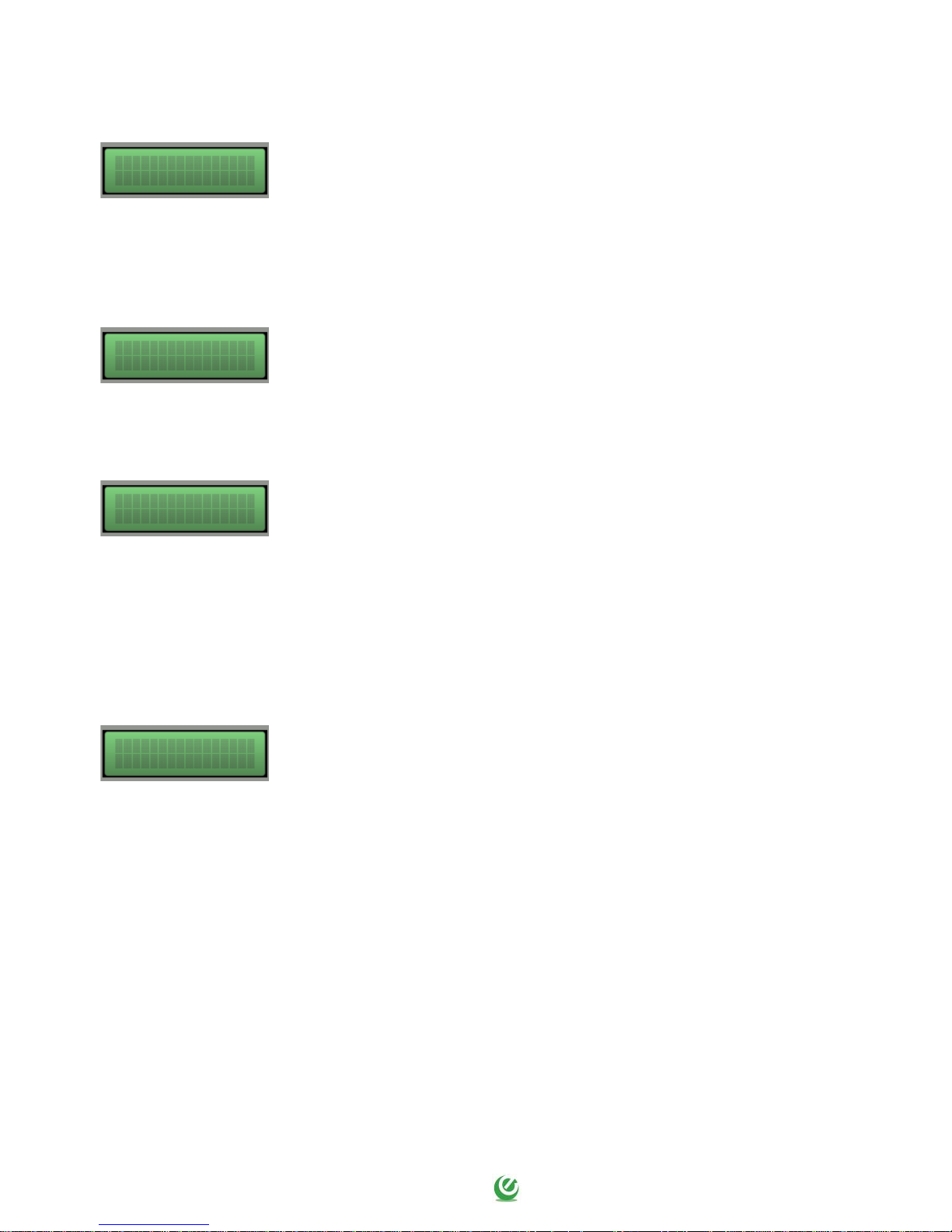
The measured power factor value is the set value and the panel shuts down
the relative pump. The display and red led blink and the cumulative alarm
output is activated (voltage-free contacts NC-C-NO).
The system resets automatically on the basis of the times set during programming.
To reset the alarm manually press the UP or DOWN arrow button and then the OK button.
The load current absorption is higher than the set value and the panel
shuts down the relative pump. The display and red led blink and the
cumulative alarm output is activated (voltage-free contacts NC-C-NO).
To reset the alarm manually press the UP or DOWN arrow button and then the OK button.
The thermal cutout of the motor (klicson) has tripped on temperature
overload. The display and red led blink and the cumulative alarm output is
activated (voltage-free contacts NC-C-NO).
If not used, close the motor klicson input.
The system is reset automatically when the motor Klicson closes. To reset the alarm manually press
the UP or DOWN arrow button and then the OK button.
In the event of motor overtemperature alarm the pumps do not stop.
The measured mains voltage is too low (the pumps are shut down).
The display and red led blink and the cumulative alarm output is activated
(voltage-free contacts NC-C-NO).
The system is reset automatically when voltage goes back up.
To reset the alarm manually press the UP or DOWN arrow button and then the OK button.
ALARM MOTOR ...
DRY RUNNING
ALARM VOLTAGE
TOO LOW
ALARM MOTOR ...
IN PROTECTION
ALARM MOTOR ...
OVERTEMPERATURE
Page 33
33
The measured mains voltage is too high (the pumps are shut down).
The display and red led blink and the cumulative alarm output is activated
(voltage-free contacts NC-C-NO).
The system is reset automatically when voltage goes back down.
To reset the alarm manually press the UP or DOWN arrow button and then the OK button.
The phase sequence is incorrect or one or more phases is missing (the
pumps are shut down). The display and red led blink and the cumulative
alarm output is activated (voltage-free contacts NC-C-NO).
The system is reset manually turning off and on the electrical panel after reconnecting the phases
correctly.
The alarm float detects maximum level reached (the pumps are not shut
down). The display and red led blink and the cumulative alarm output is
activated (voltage-free contacts NC-C-NO).
The system is reset automatically when the alarm float switch contact opens.
To reset the alarm manually press the UP or DOWN arrow button and then the OK button.
The alarm is repeated if the level does not fall.
Connection problems between motherboard and expansion modules.
The display and red led blink and the cumulative alarm output is activated
(voltage-free contacts NC-C-NO).
To reset the alarm manually press the UP or DOWN arrow button and then the OK button.
Check the connection of the flat cable between the boards Mainbord and EXP.
The minimum level float or minimum level sensors detect minimum level
reached (the pumps are shut down). The display and red led blink and the
cumulative alarm output is activated (volt-free contacts NC-C-NO).
The system is reset automatically when the min level float switch contact closes.
To reset the alarm manually press the UP or DOWN arrow button and then the OK button.
This alarm can be disabled in the ASSISTANCE menu.
ALARM VOLTAGE
TOO HIGH
ALARM SEQUENCE
OR LACK PHASES
ALARM MAX
LEVEL
ALARM MOTOR ...
NO COMUNICATION
ALARM MIN
LEVEL
Page 34

34
9. GENERAL CONDITIONS
9.1 Warranty
The product warranty is subject to the general terms of sale of the company Elentek S.r.l.
Acknowledgement of the warranty depends on the strict and proven observance of the operating
instructions in this booklet and application of the correct mechanical, hydraulic and electro-technical
practices.
All products are covered by a warranty valid for 12 months, which covers all construction defects of
our products and includes the replacement/repairs of defective parts.
The warranty will not be deemed valid in the event of:
- tampering with the panel (modifications without prior authorisation);
- faults due to lack of or inadequate protection and/or connection errors;
- faults caused by exceeding data plate specifications;
- normal wear and tear;
- failure by installation personnel to observe the specified operating procedures;
- accidental causes, natural disasters of any kind, such as fires, flooding, water or lightning;
The defective material must be delivered carriage paid to Elentek S.r.l., who reserves the right to
final judgement of the cause of the said defects.
The Warranty applies exclusively to restoring the original product characteristics and does not cover
material damage or physical injury.
9.2 Maintenance
EXPRESS does not require routine maintenance provided that it is used within the operating limits
and in observance of the instructions in this manual.
Special maintenance or repairs must be performed exclusively by authorised service centres.
In the event of repairs, only original spare parts must be used.
The manufacturer declines all liability for material damage or injury to persons or animals caused by
maintenance interventions performed by unauthorised personnel or using non-original materials.
9.3 Disposal
In the event of disassembly and scrapping, strictly observe local legislation regarding pollution.
Waste disposal according to material categories is recommended.
Page 35

35
10. DECLARATION OF CONFORMITY
ELENTEK Srl with registered offices in via A. Meucci, 5/11 - 35028 Piove di Sacco (PD) ITALIA,
declares under its sole responsibility that the machine:
EXPRESS series
installed and used in the ways and for the purposes described in the operation and instruction
manual complies with the provisions of the EU directives and relative amendments:
European Directive 2014/35 UE
Electromagnetic Compatibility 2014/30 UE and subsequent amendments, in compliance with
the following technical standards:
EN 61439-1
EN 55014-1
EN 61000-3-2
EN 61000-3-3
Piove di Sacco, 01.10.2018 LEGAL REPRESENTATIVE
Michele Borgato
Page 36

36
NOTES
Page 37

37
NOTES
Page 38

38
NOTES
Page 39

Page 40

ELENTEK SRL SOCIETÀ UNIPERSONALE
Via A. Meucci 5/11 - 35028 Piove di Sacco (PD) - ITALIA
Tel. +39 049 9730367 - Fax +39 049 9731063
www.elentek.com - [email protected]
P.IVA 04534630282
Cod. MQ 0022 UK
Rev. 02
Em.10.2018
 Loading...