

Page 1

threshold that can be exceeded for short periods (up to 1 minute each time).
If this condition occurs, it is enabled “PSU current derating” (“013” alarm and possibly
“014”) and ALC management algorithm to normal operating condition is replaced by
another in which the VDS and Bias control is given by power setting and, with even
higher priority, by the current supplied from power supply.
The condition of current derating is turned off when the power supplied back to the value set by the user and if the maximum current supplied from power supply is less than
or equal to the maximum allowable value for continuous operation.
Thermal management on power supply (Lifextender ®)
The algorithm of power supply management, function of temperature, is the same as
that in the RF group, and is connected logically “OR” to it.
The first level of Derating (which acts directly on the output power) is activated when
the power supply temperature exceeds 75 ° C, while the second level is activated if,
with the first ineffective, the temperature is not stable below this value. In this second
case the output power is brought below the - 3 dB, with the same procedure already
described in RF section. On the display the activation of this mechanism is manifested
by the “010” alarm, and possibly “016”.
Fault management on RF modules (Lifextender ®)
It makes the maximum output power management depending on the number of RF
amplifier modules being properly operated.
If one or more MOSFETs are considered failed (this happens when the current consumption is less than 10% of the average), RF output power is reduced to the expected
value in the presence of failure experienced. The failure case histories and maximum
power achievable are described in a complex table obtained through experimentation,
and are designed to stop MOSFETs failure, that are still operating, by avoiding that are
overly stressed by the mechanism of ALC (which would call these to supply the power
output missing).
To avoid an unnecessarily large number of alert SMS, during this stage are not sent: any
alert SMS, if validated, will be sent only after the output power adaptation procedure,
according to the parameters table, and only if -3dB condition is verified.
On the display the activation of this mechanism is manifested by the “008” and “009”
alarm.
34
Cooling Management on fans group (Lifextender ®)
The fan speed is adjusted, depending on the actual cooling needs, from a minimum of
60% to a maximum of 120% (these values may differ by different models of fan used).
The cooling need is estimated on the basis of accurate temperature measurements
that are made on RF MOSFETs and on power supply. The Cooling Management aims to
extend the lifespan of the fans, to minimize the amount of dust that can be carried by
the airflow, and to guarantee a safe operation of the apparatus, even under extreme
conditions of temperature.
Without Lifextender the fans operate at 100%.
2.3.2 Hardware protections
The hardware protection system includes:
• fast electronic and fuse protection on power supplies;
• fast electronic protection on fans power supply ;
• fast protection against excessive reflected power (ROS/VSWR), caused by a strong
mismatch of the load. This protection occurs when the value of reflected power
exceeds 10% of the direct power.
Product description
Page 2

2.4 Options
ETG models can be purchased with options :
Input modulating signal
version
MPX
Inputs:
• MPX
• Aux 1
Outputs:
• MPX monitor
STEREO
Inputs:
• Left channel
• Right channel
• MPX
• Aux1
• Aux 2
Outputs:
• MPX monitor/19 kHz
AES/EBU
Inputs:
• Left channel
• Right channel
• MPX
• Aux 1
• Aux 2
• AES-EBU
Outputs:
• MPX monitor/19 kHz
Option Purchase information
model code
BASE 00E-XAX-10 (ETG 2000.20)
00E-WAX-10 (ETG 1500.15)
00E-TAX-10 (ETG 1000.10)
00E-KAX-10 (ETG 700.7)
00E-SAX-10 (ETG 500.5)
00E-UAX-10 (ETG 300.3)
00E-VAX-10 (ETG 150)
TC/TS 00E-XAX-20 (ETG 2000.20)
00E-WAX-20 (ETG 1500.15)
00E-TAX-20 (ETG 1000.10)
00E-KAX-20 (ETG 700.7)
00E-SAX-20 (ETG 500.5)
00E-UAX-20 (ETG 300.3)
00E-VAX-20 (ETG 150)
TC/TS+ETHERNET+PROFILES 00E-XAX-15 (ETG 2000.20)
00E-WAX-15 (ETG 1500.15)
00E-TAX-15 (ETG 1000.10)
00E-KAX-15 (ETG 700.7)
00E-SAX-15 (ETG 500.5)
00E-UAX-15 (ETG 300.3)
00E-VAX-15 (ETG 150)
BASE 00E-XAA-10 (ETG 2000.20)
00E-WAA-10 (ETG 1500.15)
00E-TAA-10 (ETG 1000.10)
00E-KAA-10 (ETG 700.7)
00E-SAA-10 (ETG 500.5)
00E-UAA-10 (ETG 300.3)
00E-VAA-10 (ETG 150)
TC/TS 00E-XAA-20 (ETG 2000.20)
00E-WAA-20 (ETG 1500.15)
00E-TAA-20 (ETG 1000.10)
00E-KAA-20 (ETG 700.7)
00E-SAA-20 (ETG 500.5)
00E-UAA-20 (ETG 300.3)
00E-VAA-20 (ETG 150)
TC/TS+ETHERNET+PROFILES 00E-XAA-15 (ETG 2000.20)
00E-WAA-15 (ETG 1500.15)
00E-TAA-15 (ETG 1000.10)
00E-KAA-15 (ETG 700.7)
00E-SAA-15 (ETG 500.5)
00E-UAA-15 (ETG 300.3)
00E-VAA-15 (ETG 150)
BASE 00E-XAD-10 (ETG 2000.20)
00E-WAD-10 (ETG 1500.15)
00E-TAD-10 (ETG 1000.10)
00E-KAD-10 (ETG 700.7)
00E-SAD-10 (ETG 500.5)
00E-UAD-10 (ETG 300.3)
00E-VAD-10 (ETG 150)
TC/TS 00E-XAD-20 (ETG 2000.20)
00E-WAD-20 (ETG 1500.15)
00E-TAD-20 (ETG 1000.10)
00E-KAD-20 (ETG 700.7)
00E-SAD-20 (ETG 500.5)
00E-UAD-20 (ETG 300.3)
00E-VAD-20 (ETG 150)
TC/TS+ETHERNET+PROFILES 00E-XAD-15 (ETG 2000.20)
00E-WAD-15 (ETG 1500.15)
00E-TAD-15 (ETG 1000.10)
00E-KAD-15 (ETG 700.7)
00E-SAD-15 (ETG 500.5)
00E-UAD-15 (ETG 300.3)
00E-VAD-15 (ETG 150)
If you want the Lifextender functionality please specify it in order.
35Product description
Page 3

36 Product description
Page 4

3 Use instructions
3.1 User interface
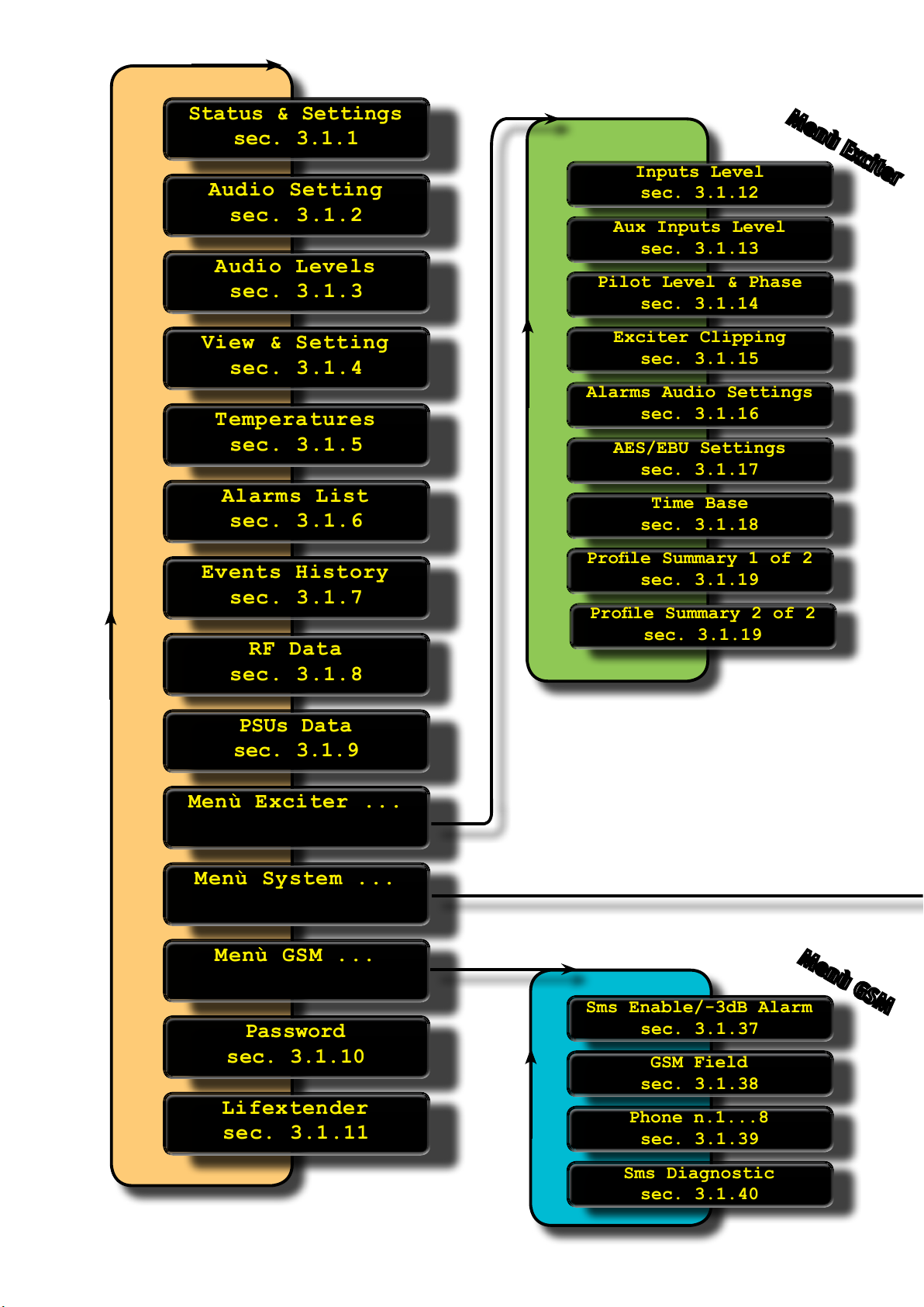
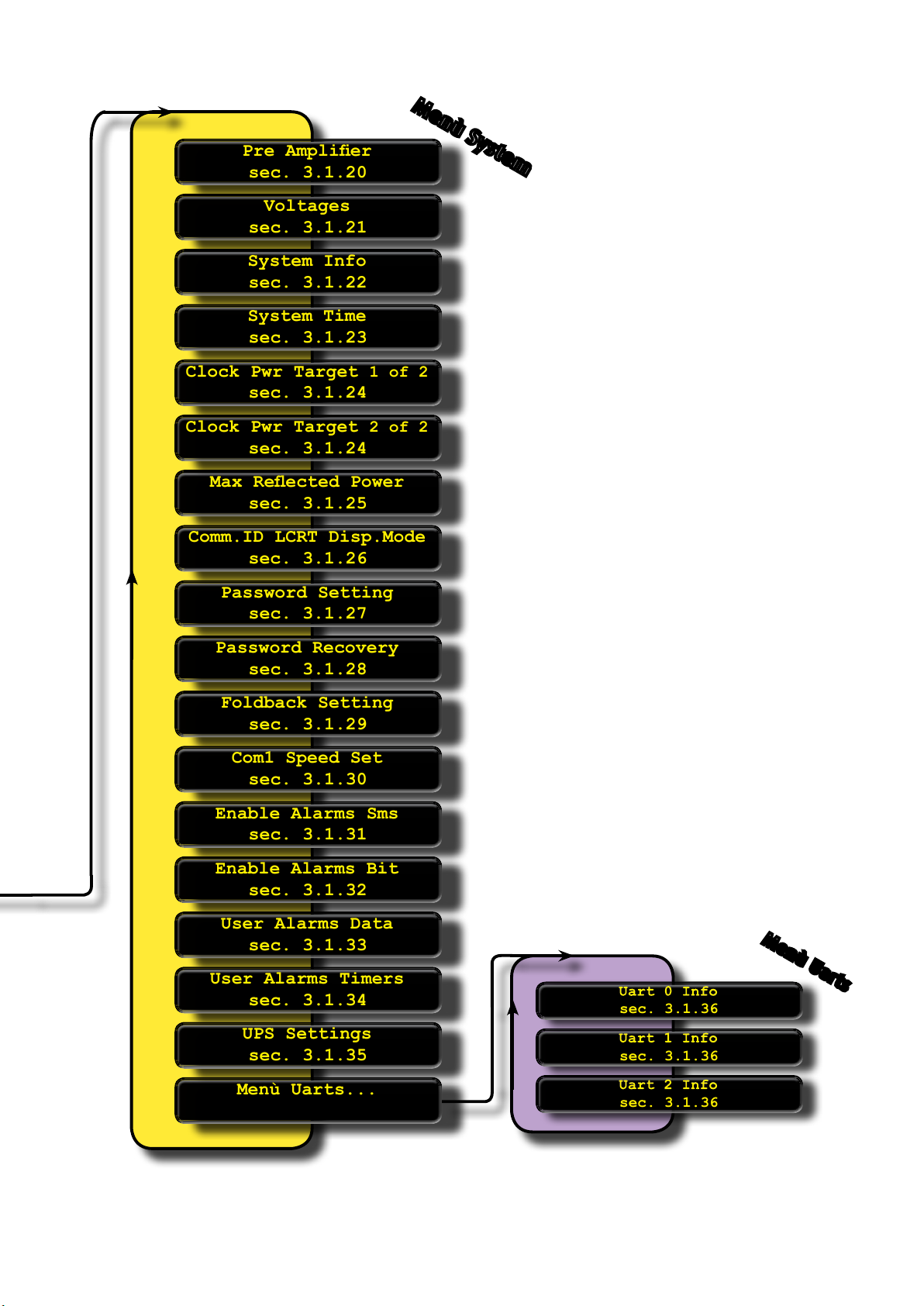
In this section there is the detail tree of menu, to view all the control interfaces and the
machine setting.
Use instructions
37
Page 5
Status & Settings
sec. 3.1.1
Status & Settings
sec. 3.1.1
Audio Setting
sec. 3.1.2
Audio Setting
sec. 3.1.2
Audio Levels
sec. 3.1.3
Audio Levels
sec. 3.1.3
View & Setting
sec. 3.1.4
View & Setting
sec. 3.1.4
Temperatures
sec. 3.1.5
Temperatures
sec. 3.1.5
Alarms List
sec. 3.1.6
Alarms List
sec. 3.1.6
Events History
sec. 3.1.7
Events History
sec. 3.1.7
RF Data
sec. 3.1.8
RF Data
sec. 3.1.8
Inputs Level
sec. 3.1.12
Inputs Level
sec. 3.1.12
Aux Inputs Level
sec. 3.1.13
Aux Inputs Level
sec. 3.1.13
Pilot Level & Phase
sec. 3.1.14
Pilot Level & Phase
sec. 3.1.14
Exciter Clipping
sec. 3.1.15
Exciter Clipping
sec. 3.1.15
Alarms Audio Settings
sec. 3.1.16
Alarms Audio Settings
sec. 3.1.16
AES/EBU Settings
sec. 3.1.17
AES/EBU Settings
sec. 3.1.17
Time Base
sec. 3.1.18
Time Base
sec. 3.1.18
Prole Summary 1 of 2
sec. 3.1.19
Prole Summary 1 of 2
sec. 3.1.19
Prole Summary 2 of 2
sec. 3.1.19
Prole Summary 2 of 2
sec. 3.1.19
Pre Amplier
sec. 3.1.20
Pre Amplier
sec. 3.1.20
Voltages
sec. 3.1.21
Voltages
sec. 3.1.21
System Info
sec. 3.1.22
System Info
sec. 3.1.22
System Time
sec. 3.1.23
System Time
sec. 3.1.23
Clock Pwr Target 1 of 2
sec. 3.1.24
Clock Pwr Target 1 of 2
sec. 3.1.24
Max Reected Power
sec. 3.1.25
Max Reected Power
sec. 3.1.25
Comm.ID LCRT Disp.Mode
sec. 3.1.26
Comm.ID LCRT Disp.Mode
sec. 3.1.26
Password Setting
sec. 3.1.27
Password Setting
sec. 3.1.27
Password Recovery
sec. 3.1.28
Password Recovery
sec. 3.1.28
Foldback Setting
sec. 3.1.29
Foldback Setting
sec. 3.1.29
Com1 Speed Set
sec. 3.1.30
Com1 Speed Set
sec. 3.1.30
Enable Alarms Sms
sec. 3.1.31
Enable Alarms Sms
sec. 3.1.31
User Alarms Data
sec. 3.1.33
User Alarms Data
sec. 3.1.33
Menù Uarts...
Menù Uarts...
sec. 3.1.36
sec. 3.1.36
sec. 3.1.36
sec. 3.1.36
sec. 3.1.36
sec. 3.1.36
Sms Enable/-3dB Alarm
sec. 3.1.37
Sms Enable/-3dB Alarm
sec. 3.1.37
GSM Field
sec. 3.1.38
GSM Field
sec. 3.1.38
Phone n.1...8
sec. 3.1.39
Phone n.1...8
sec. 3.1.39
Sms Diagnostic
sec. 3.1.40
Sms Diagnostic
sec. 3.1.40
User Alarms Timers
sec. 3.1.34
User Alarms Timers
sec. 3.1.34
Clock Pwr Target 2 of 2
sec. 3.1.24
Clock Pwr Target 2 of 2
sec. 3.1.24
Enable Alarms Bit
sec. 3.1.32
Enable Alarms Bit
sec. 3.1.32
UPS Settings
sec. 3.1.35
UPS Settings
sec. 3.1.35
PSUs Data
sec. 3.1.9
PSUs Data
sec. 3.1.9
Menù Exciter ...
Menù Exciter ...
Menù System ...
Menù System ...
Menù GSM ...
Menù GSM ...
Password
sec. 3.1.10
Password
sec. 3.1.10
Lifextender
sec. 3.1.11
Lifextender
sec. 3.1.11
LEV.1
Menù Exciter
LEV.2
Menù GSM
LEV.2
Page 6
Pre Amplier
sec. 3.1.20
Pre Amplier
sec. 3.1.20
Voltages
sec. 3.1.21
Voltages
sec. 3.1.21
System Info
sec. 3.1.22
System Info
sec. 3.1.22
System Time
sec. 3.1.23
System Time
sec. 3.1.23
Clock Pwr Target 1 of 2
sec. 3.1.24
Clock Pwr Target 1 of 2
sec. 3.1.24
Max Reected Power
sec. 3.1.25
Max Reected Power
sec. 3.1.25
Comm.ID LCRT Disp.Mode
sec. 3.1.26
Comm.ID LCRT Disp.Mode
sec. 3.1.26
Password Setting
sec. 3.1.27
Password Setting
sec. 3.1.27
Password Recovery
sec. 3.1.28
Password Recovery
sec. 3.1.28
Foldback Setting
sec. 3.1.29
Foldback Setting
sec. 3.1.29
Com1 Speed Set
sec. 3.1.30
Com1 Speed Set
sec. 3.1.30
Enable Alarms Sms
sec. 3.1.31
Enable Alarms Sms
sec. 3.1.31
User Alarms Data
sec. 3.1.33
User Alarms Data
sec. 3.1.33
Menù Uarts...
Menù Uarts...
sec. 3.1.36
sec. 3.1.36
sec. 3.1.36
sec. 3.1.36
sec. 3.1.36
sec. 3.1.36
User Alarms Timers
sec. 3.1.34
User Alarms Timers
sec. 3.1.34
Clock Pwr Target 2 of 2
sec. 3.1.24
Clock Pwr Target 2 of 2
sec. 3.1.24
Enable Alarms Bit
sec. 3.1.32
Enable Alarms Bit
sec. 3.1.32
UPS Settings
sec. 3.1.35
UPS Settings
sec. 3.1.35
LEV.2
Menù System
Menù Uarts
LEV.3
Page 7
Indication : when lit indicates that the interlock
contacts are open
Indication : when lit
indicates a power loss
below 3 dB (<50% of
target)
Indication : when lit
indicates the clipper action caused by an audio
overdriving
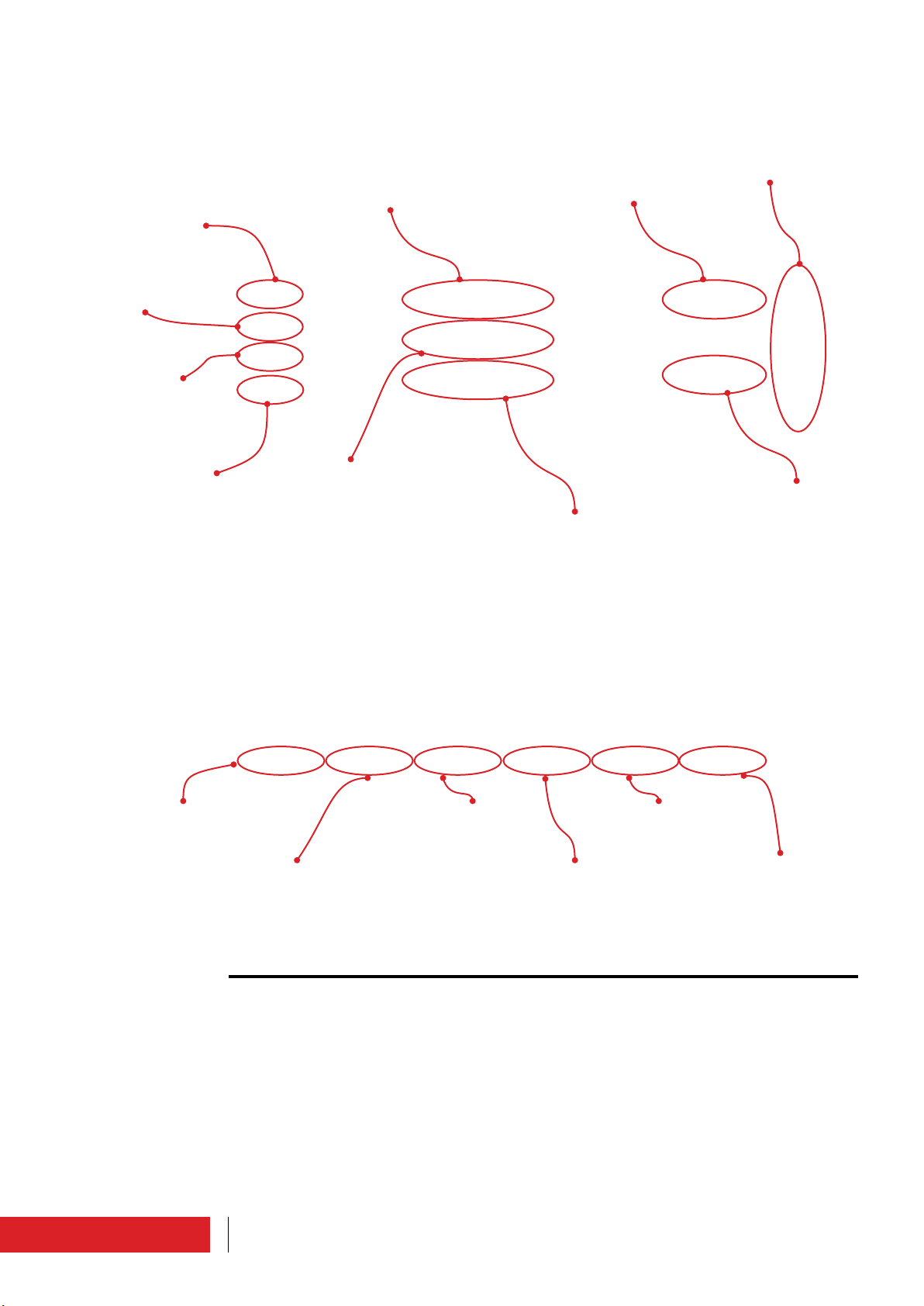
3.1.1 Status & Settings
Main screen that appears automatically on power in LOCAL.
Used to set and verify the main parameters.
Target frequency
Target audio level
Vu-meter : should
achieve near 0dB
Indication : when lit indicates no signal beyond
the preset limits
To see the list of all available manù
Forward power
To turn on, or put on
stand-by the system
To reset alarms
Forward power really
present
Per settare il
segnale audio
To set the preemphasis
level
Reflected power : must
be zero or low value
To set the profile
40 Use instructions
Page 8
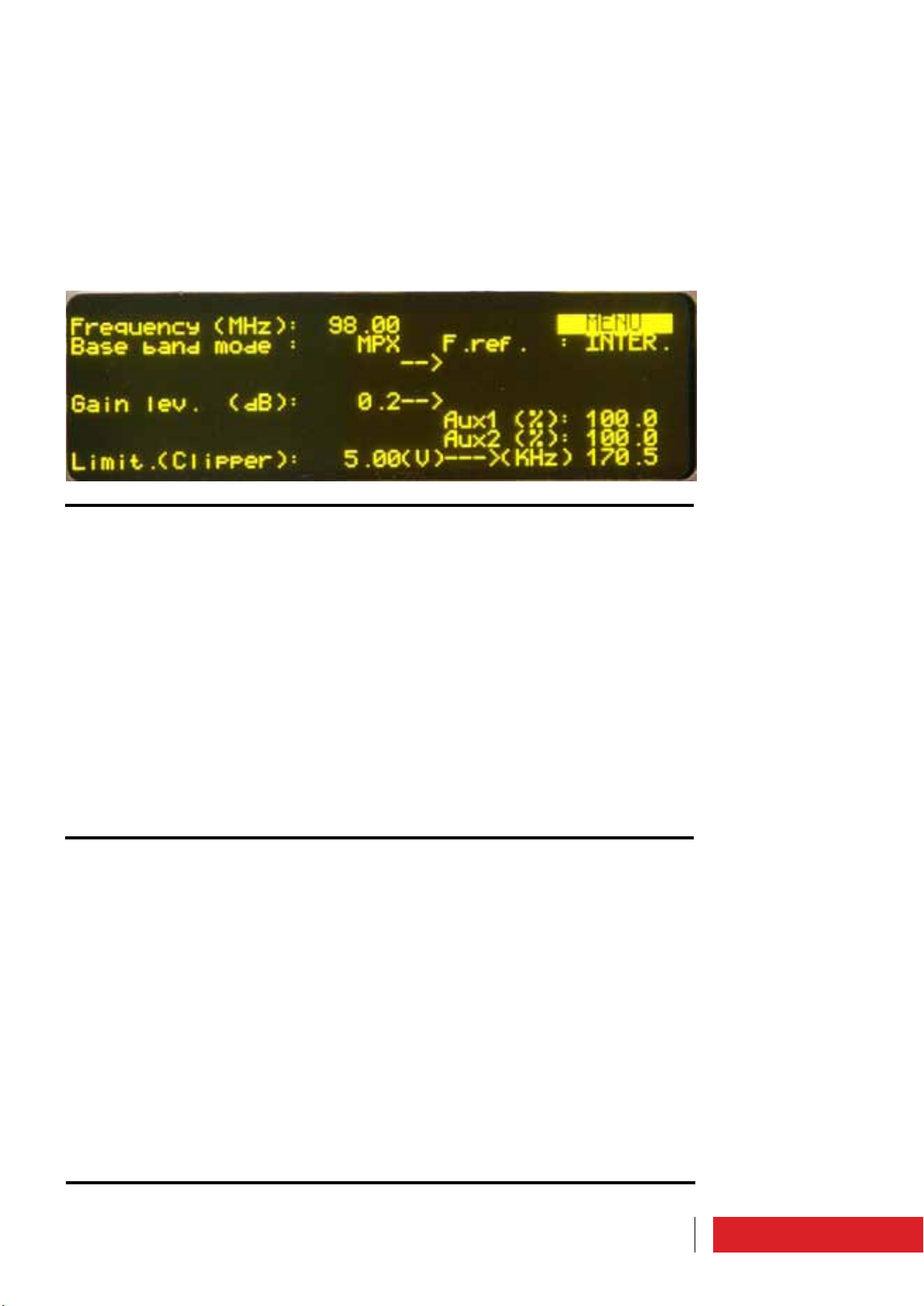
3.1.2 Audio Setting
In this window you can set a range of audio parameters accessible from other menus,
but that here are grouped together in order to speed up the setting.
They are: frequency, type of input (“Base band mode”), the internal/external reference
of the PLL (“F.ref” must be set as “INTER”), type of audio signal, pilot tone level, pilot
tone phase, audio signals level, auxiliary channels level, pre-emphasis value, clipper.
This window changes, depending on the mode of operation selected (MONO, STEREO,
MPX or MUTE).
3.1.3 Audio Levels
The value of the deviations and the level of input signals are shown.
This window changes, depending on the mode of operation selected (MONO, STEREO,
MPX or MUTE).
3.1.4 View & Setting
The following parameters are shown : frequency, target power, forward power, reflected
power, efficiency, voltage, current, and temperature.
Frequency and target power can be set through this window.
41Use instructions
Page 9
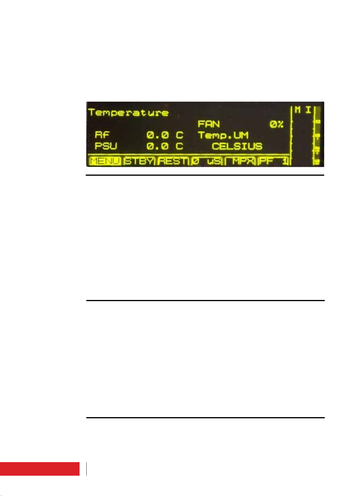
3.1.5 Temperatures
The following parameters are shown: RF temperature (max value measured from probe
on RF MOSFETs), PSU temperature (value measured from probe on power supply) and
fan speed (expressed as a percentage of nominal value).
The unit of temperature can be set in this menu, choosing between Celsius and Fahrenheit.
Warning : in ETG 700.7, ETG 500.5, ETG 300.3 and ETG 150 the indication of temperature of the power supplies and of the fan speed is not available.
3.1.6 Alarms List
Alarm list.
Those marked with the letter “A” is still active
For more detail, please see “Alarms/events list”paragraph.
3.1.7 Events History
List events (including alarms) occurred.
These are represented by code, description, date and time.
42 Use instructions
Page 10

3.1.8 RF Data
Temperatures and currents of each RF modules are displayed.
3.1.9 PSUs Data
The following parameters, related to power supply, are displayed : voltage, current,
temperature. From here you can “force” the ON/OFF status through the ENABLE flag.
Warning : in ETG 700.7, ETG 500.5, ETG 300.3 e ETG 150 the indication of temperature and ON/OFF command is not available.
3.1.10 Password
The device leaves the factory with the default password “0000”, which you then can
customize (for more detail see the paragraph “Password Setting”).
Use this screen to insert thepassword.
43Use instructions
Page 11

3.1.11 Lifextender
The parameters related to the Lifextender function are shown : serial number of the
apparatus, the apparatus code (parameter to indicate if you want to request activation/
deactivation of the functionality at a later date), activation/deactivation code (parameter provided by Elenos to enter for the on/off function), status, day of work with function active, working days in critical condition.
Critical days are those days when the device works at RF temperature and PSU temperature, and at reflected power, above a certain threshold for a certain period of time.
3.1.12 Inputs Level
To set the audio levels.
This mask differs, depending on the selected mode (MONO, STEREO, MPX or MUTE).
In STEREO or MUTE mode, where both input channels are active, there is a flag that forces the two gains to be equal.
3.1.13 Aux Inputs Level
To set the levels of the auxiliary channels expressed in percentage.
100% is equal to the maximum amplitude for 75kHz deviation.
44 Use instructions
Page 12
3.1.14 Pilot Level & Phase
To set the pilot tone level and phase.
3.1.15 Exciter Clipping
To set the maximum voltage value, in order to control the overmodulation.
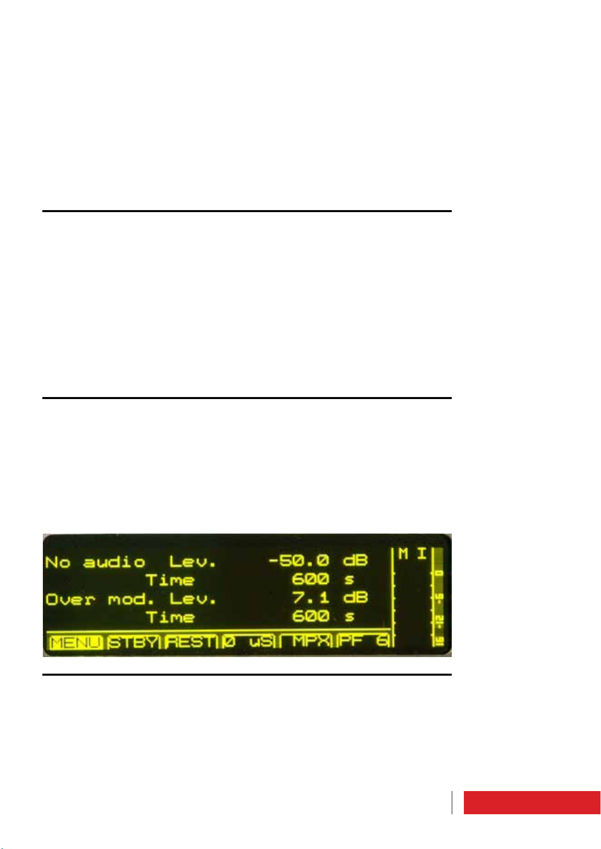
3.1.16 Alarms Audio Settings
To set these audio alarms:
• alert in case of audio absence
• alert in case of overmodulation.
In the first case should be set to the threshold of sound the time for which it must verify the condition.
In the second case must be set to the level of overmodulation and the time for which it
must verify the condition.
45Use instructions
Page 13

3.1.17 AES/EBU Settings
If you have AES/EBU connection you can still choose the ANALOG operating mode through this screen, setting “Audio input mode” properly as ANALOG or AUTO.
The “Current mode” value automatically adapts.
3.1.18 Time Base
To set the VCO synchronization, as internal (TCXO) or external.
The external reference frequency is 10,000 MHz.
The is firmware version.
3.1.19 Profile Summary
Profiles status : frequency, power, audio signal, input, pre-emphasis, audio level, clipping, voltage.
46 Use instructions
Page 14
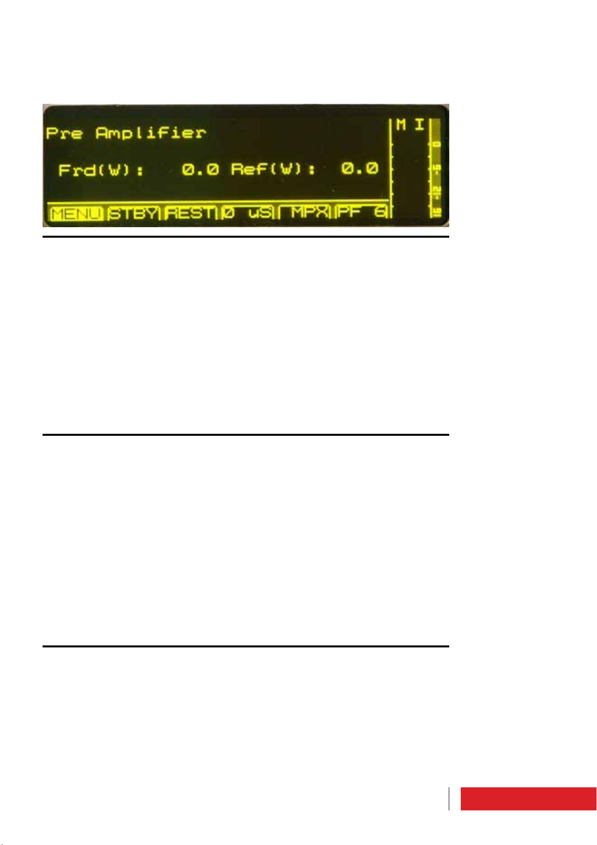
3.1.20 Pre Amplifier
Control menu related to the preamplifier.
Warning : in ETG 700.7, ETG 500.5, ETG 300.3 e ETG 150 is not available.
3.1.21 Voltages
It displays the power supplies voltages, with a comparison between nominal and actual
values.
3.1.22 System Info
It is given indication on the software version, protocol version, operating time of the
equipment, operating time of the fans.
It is possible reset this value by clicking on “R”.
47Use instructions
Page 15

3.1.23 System Time
To set the day of the week, date and time.
3.1.24 Clock Pwr Target
In addition to the standard regulation of the power you can make the setting
according to time slots, with the aim of save the energy.
To set the output power as time slots the field “Target Power Mode” must be setted as
“CLOCKED”.
It’s possible, then, attach four percent values of the power in the various times of the
day (100%, 75%, 50% or 25% of the power setted).
Defined the day of the week for which you want to start setting (“Target Power on day
of”), for each hour of the day, press the encoder to enter in the the setting bar, turn
to define the percentage (no display corresponds to 25 %, T1 corresponds to 50%, T2
corresponds to 75% and T3 corresponds to 100%), press the encoder to confirm.
By placing the field “Copy over next day” in “T” you will copy the previous day to the
next day.
By placing the field “Reset at default” in “T” you will reset the settings, switching to the
default, which provides low power at night and full power during the day.
48 Use instructions
Page 16

3.1.25 Max Reflected Power
The maximum reflected power allowable is 10% of rated output. From here you can set
a lower value.
In this case is not guaranteed a correct operation of foldback.
3.1.26 Comm.ID LC/RT Disp.Mode
To set the device address (reference for the communication).
It’s possible to activate the display (field “Show dip.on remote” as “T”) to maintain visible certain menù in REMOTE mode.
3.1.27 Password Setting
There are two levels of privileges for the user: USER and SYSTEM, both initially protected
by the default password “0000”.
In this screen you can be set different passwords, custom.
If a user has “SYSTEM” privileges has visibility and/or edit access more than a user with
“USER” privileges. The menù involved are Temperatures, PSUs Data, System Info, Clock
Pwr Target, Pre Amplifier, Max Reflected Power, Password Setting, Foldback Setting, UPS
Settings, Menù GSM, Menù Uarts.
Even here you can set the addresses of the device (reference for the communication).
49Use instructions
Page 17

3.1.28 Password Recovery
If you forget your password you can contact Elenos.
You must provide to Elenos the “Unlock Code”, in this screen.
Elenos provides a password for a period of 24 hours to be included in this screen in the
“Password Recovery”.
Then you must define a new password in “Password Setting”.
3.1.29 Foldback Setting
To enable the foldback.
3.1.30 Com1 Speed Set
To set the port speed (was recommend the value 9600.)
50 Use instructions
Page 18

3.1.31 Enable Alarms SMS
In addition to a “state” alarm management it can also be used an “event” management.
Alarms for which you enable this mode of management are put into a buffer.
If the corresponding alarm is assigned value “0” means it is off, while the value “1”
means that is enabled to be handled in “event” mode.
This feature is only available via link on Omron Protocol.
For details on the list of possible alarms see the paragraph “Alarms/events list”.
3.1.32 Enable Alarms Bit
To see the events setted in the menu “Enable Alarms SMS” (field “Enable”) and those
that are active (field “Status”).
If the “SMS/PSTN StatusReady” field is “TRUE” means that an event is active and has
been sent an alarm or a phone call. To bring the field into “FALSE” you need to reset
alarms.
3.1.33 User Alarms Data
For some alarms you can set specific conditions for activation.
In this screen is displayed the current value of the measured parameter of the condition
of the alarm, if the alarm is enabled or not, it sets a minimum and maximum value for
the parameter and choose the type of condition (upper, lower, inside, outside).
51Use instructions
Page 19

3.1.34 User Alarms Timers
For the alarms mentioned above can also set a time for which the condition must occur
to consider the alert real (“dlay).
From this screen you can also view the progress of the timer that keeps track of this
time and the enable of an alarm via a status flags.
3.1.35 UPS Settings
To set the value of power to which the machine has to work under UPS.
52 Use instructions
Page 20
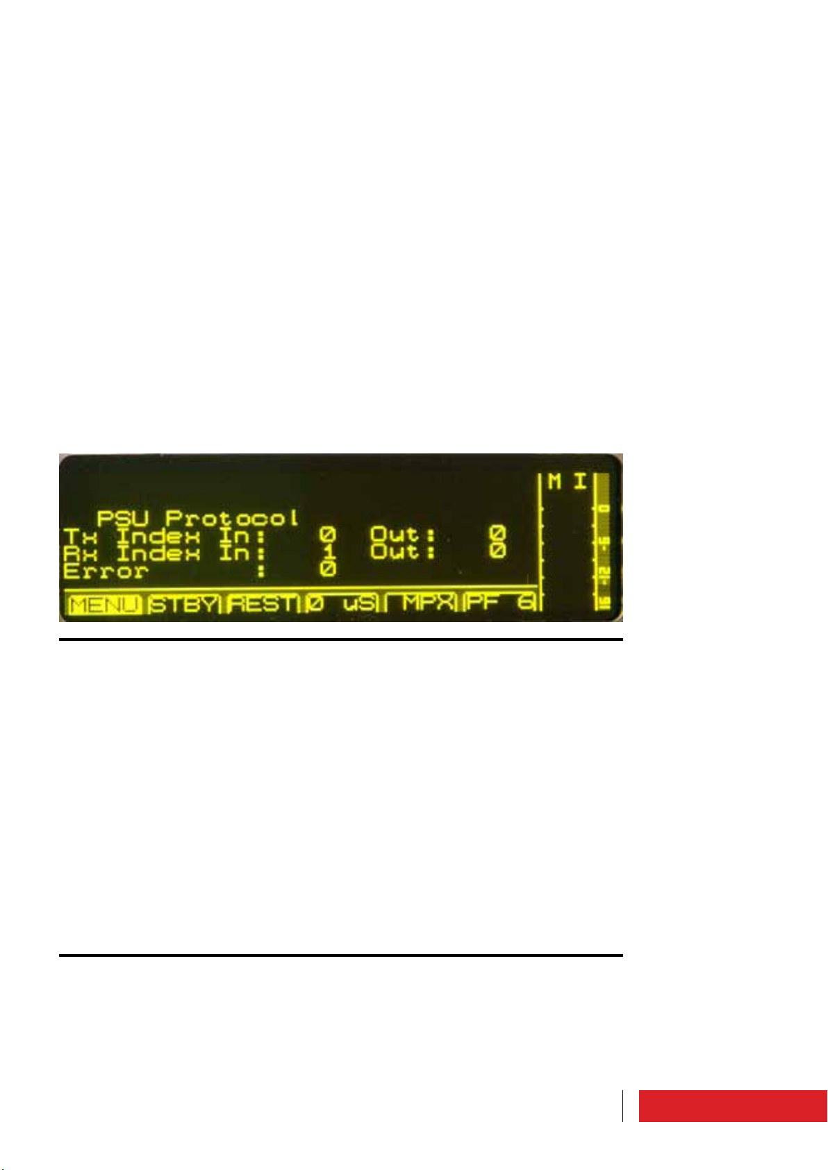
3.1.36 Uart Info
Control menu for testing the serial ports.
3.1.37 SMS Enable/-3dB Alarm
To enable the sending of -3dB alarm through SMS and/or PSTN.
Alarm that is no longer active to overcome the 2/3 of the power set.
Must be set here the various codes to message strings (String ID, Pager ID, Station ID).
53Use instructions
Page 21
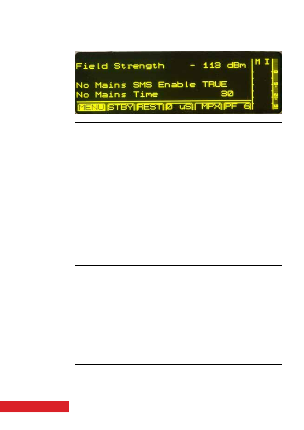
3.1.38 GSM Field
To display the field strength of the GSM signal.
To set an alarm in the absence of electricity for a time period set.
3.1.39 Phone N°
With the transmitter can “talk” more SIM cards.
The number is defined with the customer.
In these masks are setted the phone numbers in international format and the permissions.
The number can be enabled globally for transmission and reception of SMS (en.), to
send commands (cmd.), to request and receive status machine (sts.), to receive the
echo of commands sent by any other numbers (glb.), to get SMS text or digital (PC.).
3.1.40 SMS Diagnostic
To see the number of SMS sent and received successfully.
For more detail see paragraph “SMS List”.
54 Use instructions
Page 22

3.2 Alarms/events list
There is an “Alarms Management” module.
To check the alarm conditions physical and logical digital inputs are used.
Each input status is sampled and then the condition is logically drawn by a combinatorial network, to define if the alarm or signal are active.
Response time is 100ms minimum.
This module is repeatedly performed with the same priority as the ALC management, in
order to constantly monitor the occurrence of alarm causes, and thus to operate in good
time.
In a register is stored the recent events sequence, with date and time of activation.
The possible alarms/events list is:
Alarm/event Description
“000 CORRECT WORKING”
“001 SYSTEM RESET”
“002 EEPROM CHKSUM ERROR”
“003 BLOCKED”
“004 STOP”
“005 -3dB CARRIER”
“006 HIGH REF PWR”
“007 MIN 12V”
“008 RF AMP. FAULT”
“009 RF AMP. FAULT DERATING”
“010 RF THERMAL DERATING”
“011 RF OVER TEMPERATURE”
“012 PSU FAULT”
“013 PSU CURRENT DERATING”
It indicates the correct functioning. In any case
the “On air” event takes the precedence.
It indicates that the alarm reset is in progress.
All the alarms stored and no longer active are
removed from the list.
It indicates that the persistent data in memory are no longer reliable and the machine is
reconfigured with the default parameters.
It indicates that the machine is blocked after
6 attempts to restore every 5 minutes for 3
times, coming in an hour break and repeating
the procedure within 24 hours. At the end of
24 hours is required a reset by the user to enable the apparatus restart.
It indicates that the device is in stand-by,
ready to start without alarms.
It indicates that the device is providing at
least 3dB less power than the set target, at least one minute in boot or five seconds steady.
It indicates the presence of a level of output
reflected power too high, which means turning off the equipment in three block out.
It indicates that the negative reference
voltage is changed and prevents the proper
functioning of protections. Stopping in three
blocks out.
It indicate a fault, on one or more RF modules.
It indicate a fault, on one or more RF modules,
which implies a reduction of total maximum
power supplied.
It indicates a too hot temperature on the RF
modules, which implies a reduction in maximum power output.
It indicates a maximum operating temperature overcoming, resulting in shutdown of the
machine in three blocks out. This protection
occurs in extreme cases where the mechanism Derating was not enough to return to
normal temperature values.
It indicates a power supply malfunction.
It indicates the power supply overhead, which
determines the decrease in output power.
55Use instructions
Page 23

“014 PSU OVER CURRENT”
“015 PSU THERMAL DERATING”
“016 PSU OVER TEMPERATURE”
“017 PSU SHUNT COMM TIMEOUT”
“018 EXTERNAL INTERLOCK”
“019 ON AIR”
“020 POWER UP”
“ 021 POWER DOWN”
“022 PSU THERMAL FAULT”
“023 PSU LOW POWER”
“024 PSU RF OFF”
“025 WORKING MODE COMBINED”
“026 SWR FOLDBACK”
“027 UNLOCK”
“028 EXCITER COMM ERROR”
“029 NO AUDIO”
“030 OVER 2/3 CARRIER”
“031 PREAMPLIFIER NOT CONNECTED”
“032 OVER MODULATION”
“033 FAST INHIBIT”
“034 TEMPERATURE SENSOR ERROR”
“035 PWR FORWARD OSCILLATION”
“036 THREE BLOCK OUT”
“037 USER ENV TEMP OUT LIMIT”
“038 USER RF TEMP OUT LIMIT”
“039 USER PSU TEMP OUT LIMIT”
It indicates the machine turning off that
happens if after 1 minute from derating the
current does not decrease.
It indicates power supply overheating, that
determines the decrease in output power.
It indicates power supply overheating, resulting in turning off the equipment.
It indicates the IEEE485 internal bus communication malfunction, between the CPU, PSU
and shunt.
It indicates that interlock is active.
It indicates that the device is functioning pro-
perly and is being transmitted.
It indicates that is being inserted in the stora-
ge an alert regarding the restart of the device.
It indicates that is being inserted in the sto-
rage an alert regarding the shutdown of the
equipment.
It indicates a power supply overheating resulting turning off the machine. In the case of
Elenos equipment with more than one power
supply this protection is intended to allow
reduced power operation if one power supply
has been disconnected for hardware protection from excessive temperature.
In this case, with a single power supply, it
works as alarm n°022.
It indicates problems on 50V. In this case,
with a single power supply, it works as alarm
n°022.
It indicates the machine operation in a combined system.
It indicates that the machine is in power
reduction because it found too much reflected
power.
It indicates that the PLL is not locked, so the
machine is stopped.
It indicates that the PLL and VCO are not programmable.
It indicates audio signal absence.
It indicates the exceeded of 2/3 of the power
set.
It indicates that there is 100% reflected
power.
It indicates overmodulation presence.
It indicates that there are problems with the
hardware lines that lead to RF inhibition.
If there are multiple RF temperature sensors,
it indicates that one is damaged if it operates
a measure significantly different.
It indicates fluctuations in output power.
It indicates that the machine is in one-hour
break before making another attempt to
restore.
It indicates a deviation from the conditions to
set by user in relation to environment temperature measured from the apparatus.
It indicates a deviation from the conditions to
set by user in relation to RF modules temperature.
It indicates a deviation from the conditions
to set by user in relation to power supply
temperature.
56 Use instructions
Page 24

“040 USER RF CURRENT OUT LIMIT”
“041 USER PSU CURRENT OUT LIMIT”
“042 USER FRW PWR OUT LIMIT”
“043 USER RFL PWR OUT LIMIT”
“044 OUT PWR NOT VERIFIED”
“045 UPS ACTIVE”
“046 SHUNT COMM TIMEOUT”
“047 WARNING TEMPERATURE SENSOR”
“048 AUDIO OK”
3.3 SMS list
It indicates a deviation from the conditions to
set by user in relation to RF modules currents.
It indicates a deviation from the conditions
to set by user in relation to power supply
currents.
It indicates a deviation from the conditions to
set by user in relation to forward power.
It indicates a deviation from the conditions to
set by user in relation to reflected power.
It indicates that there is a problem to detect
the output power.
It indicates that the UPS is active, so the machine is using the output power to operate in
this mode.
This indicates the communication timeout
on the polarizer. It stops the operation of the
apparatus.
This indicates a fault in the temperature
probes.
This indicates that the No audio alarm is
finished.
3.3.1 SMS command (send)
You can send SMS with the text set here, to run these commands :
Command SMS text
Power setting to xxxxx
Stand-by setting
Stand-by setting
On Air setting
Status demand
Reset demand
Parameters demand
Mute mode for xx minuts
Audio activation
Activation of power output in CLOCKED
mode
Activation of power output in FIXED mode
PWR xxxxx
STBY
OFF
ON
STS
RES
STS1
MUTE xx (no in MPX)
AUDIO
CLKP
FIXP
3.3.2 SMS status/alarm (reception)
You can receive SMS with this text :
Exxxx ID xx
SMS String
+39xxxxxxxxxx
STBY
-3dB Alarm
Status
Command
No mains xx m
xxx warning SMS
SMS text Description
Device description with ID number
10 bits customizable string
Telephone number last command
The device is in Stand-By (Off)
The device is under -3dB threshold
Reply to status SMS
Command confirmation
The device was is Stand-by for the defined
time (minuts)
Stop cause or main signal
57Use instructions
Page 25

FWD yyyyy W
REFL yyyyy W
FRQ yyyyy MHz
VDS yyyyy V
IDS yyyyy A
TEMPMAX yyyyy F/C
TEMPENV yyyyy F/C
Direct power yyyyy (W)
Reflected power yyyyy (W)
Frequence yyyyy (MHz)
Voltage yyyyy (V)
Current yyyyy (A)
Max temperature yyyyy (F or C)
Environment temperature yyyyy (F or C)
58 Use instructions
Page 26

3.4 Optional equipment can be connected
ETG may be connected externally to the following units :
• PC
• Telemetry
• Exchange unit and/or Audio matrix
• Amplifier
• E.BOX module
3.4.1 PC connection
This connection is useful to examine in detail the operating parameters, for example
during the performance evaluation or repair activities.
To PC connection an interface cable must be inserted into the “Interface” connector,
DB9, on the front panel of the machine.
This cable could be shipped with the product. (Elenos code CAB0068-0).
The connection may be did also during running machine.
It’s sufficient Windows HyperTerminal program, or other equivalent program available.
To detailed procedure about the use of Hyperteminal please see Tecnhical Bulletin N°
127 (ask at the manufacturer).
CAB0068-0
Exciter
Interface
RS232
Use instructions
59
Page 27

3.4.1.1 Hyperterminal screen
Main Menu
Main Menù
Main RF Data (M)
+-----------------------------------------------------------------------------+
| ELENOS ETG500_1P S/N.06SA0000 ELENOS <id 0000> life eXtender [menu=Q] |
|-----------------------------------------------------------------------------|
| Status : 004 STOP 08:52 08/07 | Reset alarms :F |
|-----------------------------------------------------------------------------|
| Forward (W): 0 [ 500] Frequency (MHz): 98.00 RF : STBY |
| Reected (W): 0 LOCK ---- ---- ---- VDS (V): 0.0 |
| Eff. (%): 0.0 Prof.#: 1 ---- ---- ---- STER IDS (A): 0.00 |
|-----------------------------------------------------------------------------|
| MAIN MENU (level 1) ====> 08:52:00 Fr 08/07/2011 |
|-----------------------------------------------------------------------------|
| M = Main RF data |
| E = Exciter monitor +-----------------------------|
| W = All data | E L E N O S Srl |
| O = Proles | Via G.Amendola, 9 |
| S = Status/Alarms | 44028 Poggio Renatico (FE) |
| H = Events History | ITALY |
| K = Password... | Tel.+39 0532 829965 |
| Y = System... | Fax.+39 0532 829177 |
| | www.elenos.com |
| +-----------------------------|
| Ver. 2.14 /1.07 (c)2011 Elenos|
| |
+-----------------------------------------------------------------------------+
+-----------------------------------------------------------------------------+
| ELENOS ETG500_1P S/N.06SA0000 ELENOS <id 0000> life eXtender [menu=Q] |
|-----------------------------------------------------------------------------|
| Status : 004 STOP 08:52 08/07 | Reset alarms :F |
|-----------------------------------------------------------------------------|
| Forward (W): 0 [ 500] Frequency (MHz): 98.00 RF : STBY |
| Reected (W): 0 LOCK ---- ---- ---- VDS (V): 0.0 |
| Eff. (%): 0.0 Prof.#: 1 ---- ---- ---- STER IDS (A): 0.00 |
|-----------------------------------------------------------------------------|
| MAIN RF DATA ====> |
|-----------------------------------------------------------------------------|
| VDS (V): 0.0 |
| IDS (A): 0.00 |
| DC power (W): 0 |
| Efciency (%): 0.0 |
| Temperatures(C): 30.5 |
|-----------------------------------------------------------------------------|
| Working Time : 0:19:52 >45C : 0:00:00 >50C : 0:00:00 |
| Fans Working T.: 0:19:52 Reset : F |
|-----------------------------------------------------------------------------|
| Frequency (MHz): 98.00 [step 10kHz] |
| Target PWR UPS (W) : 520 |
| EEprom update N.: 49 5 115 On ram N.: 7 393 3 1618 |
| 159 199 159 185 57 233 223 |
+-----------------------------------------------------------------------------+
Main Menù
Exciter Monitor (E)
60
+-----------------------------------------------------------------------------+
| ELENOS ETG500_1P S/N.06SA0000 ELENOS <id 0000> life eXtender [menu=Q] |
|-----------------------------------------------------------------------------|
| Status : 004 STOP 08:52 08/07 | Reset alarms :F |
|-----------------------------------------------------------------------------|
|0(kHz) 15 30 45 60 75 90 105 115|
|Mpx---[-20.00][ 7.3]-------+---------+---------+---------+---------+-------+
|> |
|-20(dB) -15 -12 -9 -6 -3 0 3|
|Right+[-40.83][ 0.4]-----+---------+---------+---------+---------+---------+
|> |
|Left +[-40.83][ 0.4]-----+---------+---------+---------+---------+---------+
|> |
| 0(kHz) 10.0 20.0 30.0 40.0 50.0 60.0 70.0 |
|Aux---[ 0.0]------+---------+---------+---------+---------+---------+------+
|> |
|-----------------------------------------------------------------------------|
| Tx Frequency(MHz): 98.00 |
|-----------------------------------------------------------------------------|
| Gain level (dB): 0.2 | Mode : Stereo | SW Ver: 0.367 |
| | Pilot level : 10.00 | |
| Level L = R: TRUE | Pilot phase : 0.0 | |
| Aux1(%):100.0 Aux2(%):100.0 | Preenphasys (uS): 0 | Pll : LOCK |
+-----------------------------------------------------------------------------+
Use instructions
Page 28

+-----------------------------------------------------------------------------+
| ELENOS ETG500_1P S/N.06SA0000 ELENOS <id 0000> life eXtender [menu=Q] |
|-----------------------------------------------------------------------------|
| Status : 004 STOP 08:52 08/07 | Reset alarms :F |
|-----------------------------------------------------------------------------|
| RF CURRENTS (A) Sum: 0.00 |
|Mod n: 1 |
|Id: 0.00 |
|-----------------------------------------------------------------------------|
| Psu 1 (A): 0.0 Vcc (5V): 5.09 | STAND-BY : TRUE |
| V+ (12V): 11.89 | FREQUENCY(MHz): 98.00 |
| V- (12V): 11.17 | TARGET PWR (W): 500 |
| Ids (A): 0.0 VBias (V):-10.24 |-----------------------------------|
| Vds_PSU (V): 0.0 Vds (V): 0.0 |TEMPERATURES (C) Rf 1 : 30.5 |
| | Max RF : 30.5 |
|-----------------------------------------| |
| Fwd (W): 0 PreA Fwd (W): 0.0 | Max PSU: 0.0 |
| Ref (W): 0 | Psu 1 : 0.0 |
| Eff (%): 0.0 | |
|-----------------------------------------| |
| | |
| WORKING TIME : 0:19:52 | |
| FAN WORKING T.: 0:19:52 | Fan s.%: 0 |
+-----------------------------------------------------------------------------+
+-----------------------------------------------------------------------------+
| ELENOS ETG500_1P S/N.06SA0000 ELENOS <id 0000> life eXtender [menu=Q] |
|-----------------------------------------------------------------------------|
| Status : 004 STOP 08:52 08/07 | Reset alarms :F |
|-----------------------------------------------------------------------------|
| Forward (W): 0 [ 500] Frequency (MHz): 98.00 RF : STBY |
| Reected (W): 0 LOCK ---- ---- ---- VDS (V): 0.0 |
| Eff. (%): 0.0 Prof.#: 1 ---- ---- ---- STER IDS (A): 0.00 |
|-----------------------------------------------------------------------------|
| L e v e l s Clipping |
| # Frequency Target Mode Input Right Left Aux1 Aux2 Pree Enab. Lev.|
| MHz W dB dB % % uS V |
|Cur. 98.00 500 Stereo AUTO 0.2 0.2 100.0 100.0 0 OFF 5.00 |
| |
| 1 ------ ---- ------- ------- ---- ---- ----- ----- -- --- ---- |
| 2 98.00 550 Ext.MPX AUTO 6.0 6.0 100.0 100.0 0 OFF 5.00 |
| 3 98.00 550 Ext.MPX AUTO 6.0 6.0 100.0 100.0 0 OFF 5.00 |
| 4 98.00 550 Ext.MPX AUTO 6.0 6.0 100.0 100.0 0 OFF 5.00 |
| 5 98.00 550 Ext.MPX AUTO 6.0 6.0 100.0 100.0 0 OFF 5.00 |
| 6 98.00 550 Ext.MPX AUTO 6.0 6.0 100.0 100.0 0 OFF 5.00 |
| |
| Current Prole # : 1 |
| Delta F (+/- KHz): 7.3 |
+-----------------------------------------------------------------------------+
Main Menù
All Data (W)
Highlighted parameters not
present in ETG 150,
ETG 300.3, ETG 500.5 and
ETG 700.7
Main Menù
Profiles (O)
+-----------------------------------------------------------------------------+
| ELENOS ETG500_1P S/N.06SA0000 ELENOS <id 0000> life eXtender [menu=Q] |
|-----------------------------------------------------------------------------|
| Status : 004 STOP 08:52 08/07 | Reset alarms :F |
|-----------------------------------------------------------------------------|
| STATUS/ALARMS (1 - 17) ==> |
| ACTIVE 004 STOP |
| 044 OUT PWR NOT VERIFIED |
| 045 UPS ACTIVE |
| 005 -3dB CARRIER |
| |
| |
| |
| |
| |
| |
| |
| |
| |
| |
| |
| |
| |
+-----------------------------------------------------------------------------+
Use instructions
Main Menù
Status/Alarms(S)
61
Page 29

Main Menù
Events History (H)
Main Menù
Password (K)
+-----------------------------------------------------------------------------+
| ELENOS ETG500_1P S/N.06SA0000 ELENOS <id 0000> life eXtender [menu=Q] |
|-----------------------------------------------------------------------------|
| ALARMS HISTORY ==> ([-] prev.pag. [+] next pag. [arrow up/down] next/prev.)|
| 107) 020 POWER UP 08/07 08:52:00 |
| 106) 021 POWER DOWN 08/07 08:52:00 |
| 105) 020 POWER UP 08/07 08:52:00 |
| 104) 021 POWER DOWN 08/07 08:52:00 |
| 103) 020 POWER UP 08/07 08:52:00 |
| 102) 021 POWER DOWN 08/07 08:52:00 |
| 101) 004 STOP 08/07 08:52:00 |
| 100) 030 OVER 2/3 CARRIER 08/07 08:52:00 |
| 99) 019 ON AIR 08/07 08:52:00 |
| 98) 020 POWER UP 08/07 08:52:00 |
| 97) 021 POWER DOWN 08/07 08:52:00 |
| 96) 004 STOP 08/07 08:52:00 |
| 95) 030 OVER 2/3 CARRIER 08/07 08:52:00 |
| 94) 019 ON AIR 08/07 08:52:00 |
| 93) 020 POWER UP 08/07 08:52:00 |
| 92) 021 POWER DOWN 08/07 08:52:00 |
| 91) 004 STOP 08/07 08:52:00 |
| 90) 019 ON AIR 08/07 08:52:00 |
| 89) 004 STOP 08/07 08:52:00 >> |
+-----------------------------------------------------------------------------+
+-----------------------------------------------------------------------------+
| ELENOS ETG500_1P S/N.06SA0000 ELENOS <id 0000> life eXtender [menu=Q] |
|-----------------------------------------------------------------------------|
| Status : 004 STOP 08:52 08/07 | Reset alarms :F |
|-----------------------------------------------------------------------------|
| Forward (W): 0 [ 500] Frequency (MHz): 98.00 RF : STBY |
| Reected (W): 0 LOCK ---- ---- ---- VDS (V): 0.0 |
| Eff. (%): 0.0 Prof.#: 1 ---- ---- ---- STER IDS (A): 0.00 |
|-----------------------------------------------------------------------------|
| ACCESS MENU (level 1) ====> 08:52:00 Fr 08/07/2011 |
|-----------------------------------------------------------------------------|
| K = Password |
| R = Password reset +-----------------------------|
| P = Password settings | E L E N O S Srl |
| Q = Exit | Via G.Amendola, 9 |
| | 44028 Poggio Renatico (FE) |
| | ITALY |
| | Tel.+39 0532 829965 |
| | Fax.+39 0532 829177 |
| | www.elenos.com |
| +-----------------------------|
| Ver. 2.14 /1.07 (c)2011 Elenos|
| |
+-----------------------------------------------------------------------------+
62
Main Menù
Password (K)
Password (K)
+-----------------------------------------------------------------------------+
| ELENOS ETG500_1P S/N.06SA0000 ELENOS <id 0000> life eXtender [menu=Q] |
|-----------------------------------------------------------------------------|
| Status : 004 STOP 08:52 08/07 | Reset alarms :F |
|-----------------------------------------------------------------------------|
| Forward (W): 0 [ 500] Frequency (MHz): 98.00 RF : STBY |
| Reected (W): 0 LOCK ---- ---- ---- VDS (V): 0.0 |
| Eff. (%): 0.0 Prof.#: 1 ---- ---- ---- STER IDS (A): 0.00 |
|-----------------------------------------------------------------------------|
| PASSWORD ===> |
|-----------------------------------------------------------------------------|
| |
| Password : |
| |
| |
| |
| |
| |
| |
| |
| |
| |
| |
+-----------------------------------------------------------------------------+
Use instructions
Page 30

+-----------------------------------------------------------------------------+
| ELENOS ETG500_1P S/N.06SA0000 ELENOS <id 0000> life eXtender [menu=Q] |
|-----------------------------------------------------------------------------|
| Status : 004 STOP 08:52 08/07 | Reset alarms :F |
|-----------------------------------------------------------------------------|
| Forward (W): 0 [ 500] Frequency (MHz): 98.00 RF : STBY |
| Reected (W): 0 LOCK ---- ---- ---- VDS (V): 0.0 |
| Eff. (%): 0.0 Prof.#: 1 ---- ---- ---- STER IDS (A): 0.00 |
|-----------------------------------------------------------------------------|
| PASSWORD RESET ===> |
|-----------------------------------------------------------------------------|
| |
| Unlock Code : 0923 |
| Password Recovery : 0000 |
| |
| |
| |
| |
| |
| |
| |
| |
| |
+-----------------------------------------------------------------------------+
Main Menù
Password (K)
Password reset (R)
+-----------------------------------------------------------------------------+
| ELENOS ETG500_1P S/N.06SA0000 ELENOS <id 0000> life eXtender [menu=Q] |
|-----------------------------------------------------------------------------|
| Status : 004 STOP 08:52 08/07 | Reset alarms :F |
|-----------------------------------------------------------------------------|
| Forward (W): 0 [ 500] Frequency (MHz): 98.00 RF : STBY |
| Reected (W): 0 LOCK ---- ---- ---- VDS (V): 0.0 |
| Eff. (%): 0.0 Prof.#: 1 ---- ---- ---- STER IDS (A): 0.00 |
|-----------------------------------------------------------------------------|
| PASSWORD SETTINGS ===> |
|-----------------------------------------------------------------------------|
| |
| |
| User password (n.): 0000 |
| System password (n.): 0000 |
| |
| |
| |
| |
| |
| |
| |
| |
+-----------------------------------------------------------------------------+
+-----------------------------------------------------------------------------+
| ELENOS ETG500_1P S/N.06SA0000 ELENOS <id 0000> life eXtender [menu=Q] |
|-----------------------------------------------------------------------------|
| Status : 004 STOP 08:52 08/07 | Reset alarms :F |
|-----------------------------------------------------------------------------|
| Forward (W): 0 [ 500] Frequency (MHz): 98.00 RF : STBY |
| Reected (W): 0 LOCK ---- ---- ---- VDS (V): 0.0 |
| Eff. (%): 0.0 Prof.#: 1 ---- ---- ---- STER IDS (A): 0.00 |
|-----------------------------------------------------------------------------|
| SYSTEM MENU (level 2) ====> 08:52:00 Fr 08/07/2011 |
|-----------------------------------------------------------------------------|
| X = System settings |
| U = Comm. settings +-----------------------------|
| J = Audio trim & alrm | E L E N O S Srl |
| C = Clock power set | Via G.Amendola, 9 |
| P = SMS Phone set. | 44028 Poggio Renatico (FE) |
| | ITALY |
| F = User Warning | Tel.+39 0532 829965 |
| V = En. 0-31 Alrm SMS | Fax.+39 0532 829177 |
| B = En.32-63 Alrm SMS | www.elenos.com |
| L = Life eXtender +-----------------------------|
| Ver. 2.14 /1.07 (c)2011 Elenos|
| Q = Exit |
+-----------------------------------------------------------------------------+
Main Menù
Password (K)
Password settings (P)
Main Menù
System (Y)
Use instructions
63
Page 31

Main Menù
System (Y)
System settings (X)
Main Menù
System (Y)
Comm. settings (U)
Main Menù
System (Y)
Audio trim & alrm (J)
+-----------------------------------------------------------------------------+
| ELENOS ETG500_1P S/N.06SA0000 ELENOS <id 0000> life eXtender [menu=Q] |
|-----------------------------------------------------------------------------|
| Status : 004 STOP 08:52 08/07 | Reset alarms :F |
|-----------------------------------------------------------------------------|
| Forward (W): 0 [ 500] Frequency (MHz): 98.00 RF : STBY |
| Reected (W): 0 LOCK ---- ---- ---- VDS (V): 0.0 |
| Eff. (%): 0.0 Prof.#: 1 ---- ---- ---- STER IDS (A): 0.00 |
|-----------------------------------------------------------------------------|
| SYSTEM SETTINGS ===> |
|-----------------------------------------------------------------------------|
| Temperature Unit : CELSIUS |
| Show Display : ALWAYS |
| PLL reference (10MHz) : INT. |
| Fwd Pwr Cal. (%): 100 |
| SWR Foldback Enable : FALSE |
| IPA Bias Treshold (V): 4.48 |
| Re. Pwr Tresh. nom. (10%): TRUE |
| Re. Pwr Tresh. Level (W): 55 |
| PAbias (V): 5.45 |
|-----------------------------------------------------------------------------|
| Actual date : 08/07/2011 05 08:52:00 |
| New date : 08/07/2011 05 08:52:00 UPDATE |
+-----------------------------------------------------------------------------+
+-----------------------------------------------------------------------------+
| ELENOS ETG500_1P S/N.06SA0000 ELENOS <id 0000> life eXtender [menu=Q] |
|-----------------------------------------------------------------------------|
| Status : 004 STOP 08:52 08/07 | Reset alarms :F |
|-----------------------------------------------------------------------------|
| Forward (W): 0 [ 500] Frequency (MHz): 98.00 RF : STBY |
| Reected (W): 0 LOCK ---- ---- ---- VDS (V): 0.0 |
| Eff. (%): 0.0 Prof.#: 1 ---- ---- ---- STER IDS (A): 0.00 |
|-----------------------------------------------------------------------------|
| COMM. SETTINGS ===> |
|-----------------------------------------------------------------------------|
| Front 485 Id (n.): 0 Front 485 Speed : 9600|
| TcTs 485 Id (n.): 0 |
| |
| Station Id : 0 |
| Pager Id : 0 |
| |
| |
| |
| |
| |
| |
| |
+-----------------------------------------------------------------------------+
+-----------------------------------------------------------------------------+
| ELENOS ETG500_1P S/N.06SA0000 ELENOS <id 0000> life eXtender [menu=Q] |
|-----------------------------------------------------------------------------|
| Status : 004 STOP 08:52 08/07 | Reset alarms :F |
|-----------------------------------------------------------------------------|
| Forward (W): 0 [ 500] Frequency (MHz): 98.00 RF : STBY |
| Reected (W): 0 LOCK ---- ---- ---- VDS (V): 0.0 |
| Eff. (%): 0.0 Prof.#: 1 ---- ---- ---- STER IDS (A): 0.00 |
|-----------------------------------------------------------------------------|
| |
| |
| |
| Pilot level : 10.00 |
| Pilot phase : 0.0 |
| Limiter(Clipper): 5.00 V |
|-----------------------------------------------------------------------------|
| |
| |
| |
| |
|-----------------------------------------------------------------------------|
| No audio level (dB): -50.0 Time (s): 600 |
| Over mod. level (dB): 7.1 Time (s): 600 |
+-----------------------------------------------------------------------------+
64
Use instructions
Page 32

+-----------------------------------------------------------------------------+
| ELENOS ETG500_1P S/N.06SA0000 ELENOS <id 0000> life eXtender [menu=Q] |
|-----------------------------------------------------------------------------|
| Status : 004 STOP 08:52 08/07 | Reset alarms :F |
|-----------------------------------------------------------------------------|
| CLOCK POWER SET ===> |
|-----------------------------------------------------------------------------|
| Target power mode xed for all the 24 hours: TRUE |
| Fixed target power (W): 500 |
|-----------------------------------------------------------------------------|
| copy over next day : FALSE |
| reset all at factory default : FALSE |
| |
| Target power on the 24 hours of Friday (5 of 7) |
|T3 # # # # # # # # # # # # # # # # # # # # # # # # |
|T2 # # # # # # # # # # # # # # # # # # # # # # # # |
|T1 # # # # # # # # # # # # # # # # # # # # # # # # |
|T0 00 01 02 03 04 05 06 07 08 09 10 11 12 13 14 15 16 17 18 19 20 21 22 23 |
| Hours |
| Target 3: 500 = 100% of xed target power |
| Target 2: 375 = 75% of xed target power |
| Target 1: 250 = 50% of xed target power |
| Target 0: 125 = 25% of xed target power |
|-----------------------------------------------------------------------------+
Main Menù
System (Y)
Clock power set (C)
+-----------------------------------------------------------------------------+
| ELENOS ETG500_1P S/N.06SA0000 ELENOS <id 0000> life eXtender [menu=Q] |
|-----------------------------------------------------------------------------|
| Status : 004 STOP 08:52 08/07 | Reset alarms :F |
|-----------------------------------------------------------------------------|
| SMS PHONE SET ===> |
|-----------------------------------------------------------------------------|
| Field Strength dBm: - 113 | this |status |command|global | dig. |
| > |account|request|execute|echo rx| SMS |
| Example : +393371234567890123 |-------+-------+-------+-------+-------|
| Phone N.1: | FALSE | FALSE | FALSE | FALSE | T_SMS |
| Phone N.2: | FALSE | FALSE | FALSE | FALSE | T_SMS |
| Phone N.3: | FALSE | FALSE | FALSE | FALSE | T_SMS |
| Phone N.4: | FALSE | FALSE | FALSE | FALSE | T_SMS |
| Phone N.5: | FALSE | FALSE | FALSE | FALSE | T_SMS |
| Phone N.6: | FALSE | FALSE | FALSE | FALSE | T_SMS |
| Phone N.7: | FALSE | FALSE | FALSE | FALSE | T_SMS |
| Phone N.8: | FALSE | FALSE | FALSE | FALSE | T_SMS |
|-------------------------------------+---------------------------------------|
| Id string: ELENOS | Enable SMS : FALSE PSTN : FALSE |
| Ok Bad | Mains alarm Enable : FALSE |
| Sms sended 0 0 | Mains alarm delay (m): 30 |
| Sms received 0 0 | FWD over 2/3 TARGET (-1,76DB): FALSE |
+-----------------------------------------------------------------------------+
+-----------------------------------------------------------------------------+
| ELENOS ETG500_1P S/N.06SA0000 ELENOS <id 0000> life eXtender [menu=Q] |
|-----------------------------------------------------------------------------|
| Status : 004 STOP 08:52 08/07 | Reset alarms :F |
|-----------------------------------------------------------------------------|
| Forward (W): 0 [ 500] Frequency (MHz): 98.00 RF : STBY |
| Reected (W): 0 LOCK ---- ---- ---- VDS (V): 0.0 |
| Eff. (%): 0.0 Prof.#: 1 ---- ---- ---- STER IDS (A): 0.00 |
|-----------------------------------------------------------------------------|
| USER LIMIT WARNING SETTING ====> |
|-----------------------------------------------------------------------------|
| Act.Value Enable Max Min Type Delay Timer Alarm |
| |
|RF Temp (C): 30.9 F 90.0 98.0 UPPER 120 1200 F |
|PSU Temp (C): 0.0 F 90.0 98.0 UPPER 120 1200 F |
|PSU Current (A): 0.0 F 50.0 45.0 UPPER 120 1200 F |
|RF Current (A): 0.00 F 1.20 1.00 UPPER 120 1200 F |
|Forward PWR (%): 0 F 500 400 LOWER 120 1200 F |
|Reected PWR (W): 0 F 100 90 UPPER 120 1200 F |
|-----------------------------------------------------------------------------|
| |
| |
| |
+-----------------------------------------------------------------------------+
Main Menù
System (Y)
SMS phone set. (P)
Main Menù
System (Y)
User Warning (F)
Use instructions
65
Page 33

Main Menù
System (Y)
En. 0-31 Alrm SMS (V)
Main Menù
System (Y)
En. 32-63 Alrm SMS (B)
+-----------------------------------------------------------------------------+
| ELENOS ETG500_1P S/N.06SA0000 ELENOS <id 0000> life eXtender [menu=Q] |
|-----------------------------------------------------------------------------|
| Status : 004 STOP 08:52 08/07 | Reset alarms :F |
|-----------------------------------------------------------------------------|
|Bit Status Bit Status |
| | / Enable | / Enable |
| 0 F F 000 CORRECT WORKING 16 F F 016 PSU OVER TEMPERATURE |
| 1 F F 001 SYSTEM RESET 17 F F 017 PSU COMM TIMEOUT |
| 2 F F 002 EEPROM CHKSUM ERROR 18 F F 018 EXTERNAL INTERLOCK |
| 3 F F 003 BLOCKED 19 F F 019 ON AIR |
| 4 T F 004 STOP 20 F F 020 POWER UP |
| 5 F T 005 -3dB CARRIER 21 F F 021 POWER DOWN |
| 6 F F 006 HIGH REF PWR 22 F F 022 PSU THERMAL FAULT |
| 7 F F 007 MIN 12V 23 F F 023 PSU LOW POWER |
| 8 F F 008 RF AMP. FAULT 24 F F 024 PSU RF OFF |
| 9 F F 009 RF AMP. FAULT DERATING 25 F F 025 WORKING MODE COMBINED |
|10 F F 010 RF THERMAL DERATING 26 F F 026 SWR FOLDBACK |
|11 F F 011 RF OVER TEMPERATURE 27 F F 027 UNLOCK |
|12 F F 012 PSU FAULT 28 F F 028 EXCITER COMM ERROR |
|13 F F 013 PSU CURRENT DERATING 29 F T 029 NO AUDIO |
|14 F F 014 PSU OVER CURRENT 30 F F 030 OVER 2/3 CARRIER |
|15 F F 015 PSU THERMAL DERATING 31 F F 031 PREAMPLIFIER NOT CONNEC |
+-----------------------------------------------------------------------------+
+-----------------------------------------------------------------------------+
| ELENOS ETG500_1P S/N.06SA0000 ELENOS <id 0000> life eXtender [menu=Q] |
|-----------------------------------------------------------------------------|
| Status : 004 STOP 08:52 08/07 | Reset alarms :F |
|-----------------------------------------------------------------------------|
|Bit Status Bit Status |
| | / Enable | / Enable |
|32 F F 032 OVER MODULATION 48 F F |
|33 F F 033 FAST INHIBIT 49 F F |
|34 F F 034 TEMPERATURE SENSOR ERRO |
|35 F F 035 PWR FORWARD OSCILATION |
|36 F F 036 THREE BLOCK OUT |
|37 F F 037 USER ENV TEMP OUT LIMIT |
|38 F F 038 USER RF TEMP OUT LIMIT |
|39 F F 039 USER PSU TEMP OUT LIMIT |
|40 F F 040 USER RF CURRENT OUT LIM |
|41 F F 041 USER PSU CURRENT OUT LI |
|42 F F 042 USER FRW PWR OUT LIMIT |
|43 F F 043 USER RFL PWR OUT LIMIT |
|44 F F 044 OUT PWR NOT VERIFIED |
|45 F F 045 UPS ACTIVE |
|46 F F |
|47 F F |
+-----------------------------------------------------------------------------+
66
Main Menù
System (Y)
Life eXtender (L)
+-----------------------------------------------------------------------------+
| ELENOS ETG500_1P S/N.06SA0000 ELENOS <id 0000> life eXtender [menu=Q] |
|-----------------------------------------------------------------------------|
| Status : 004 STOP 08:52 08/07 | Reset alarms :F |
|-----------------------------------------------------------------------------|
| Forward (W): 0 [ 500] Frequency (MHz): 98.00 RF : STBY |
| Reected (W): 0 LOCK ---- ---- ---- VDS (V): 0.0 |
| Eff. (%): 0.0 Prof.#: 1 ---- ---- ---- STER IDS (A): 0.00 |
|-----------------------------------------------------------------------------|
| LIFE EXTENDER ACTIVATION / DEACTIVATION ===> |
|-----------------------------------------------------------------------------|
| SerialNumber : 06SA0000 |
| Unlock Code : fe98 |
| Deactivation Code : |
| |
| LIFE EXTENDER Status : ACTIVE |
| Working Days Good Condition : 3 |
| Working Days Critical Cond. : 0 |
| Working Time : 0 |
| |
| |
| |
| |
+-----------------------------------------------------------------------------+
Use instructions
Page 34

3.4.2 Telemetry connection
This connection allows remote control through the equipment specifically designed
for that purpose. The telemetry unit provides backup energy for the continuous operation of the modem, and is equipped with all utilities for equipments and station paramenters supervision.
To telemetry connection a cable must be inserted into “EIA485” connector, DB9, on the
rear panel of the machine.
This cable is shipped with telemetry unit (Elenos code ETGSAL33).
The connection may be did also during running machine.
For more information, please see “Telemetry” manual.
Exciter
ETGSAL33
Echos3
Use instructions
67
Page 35

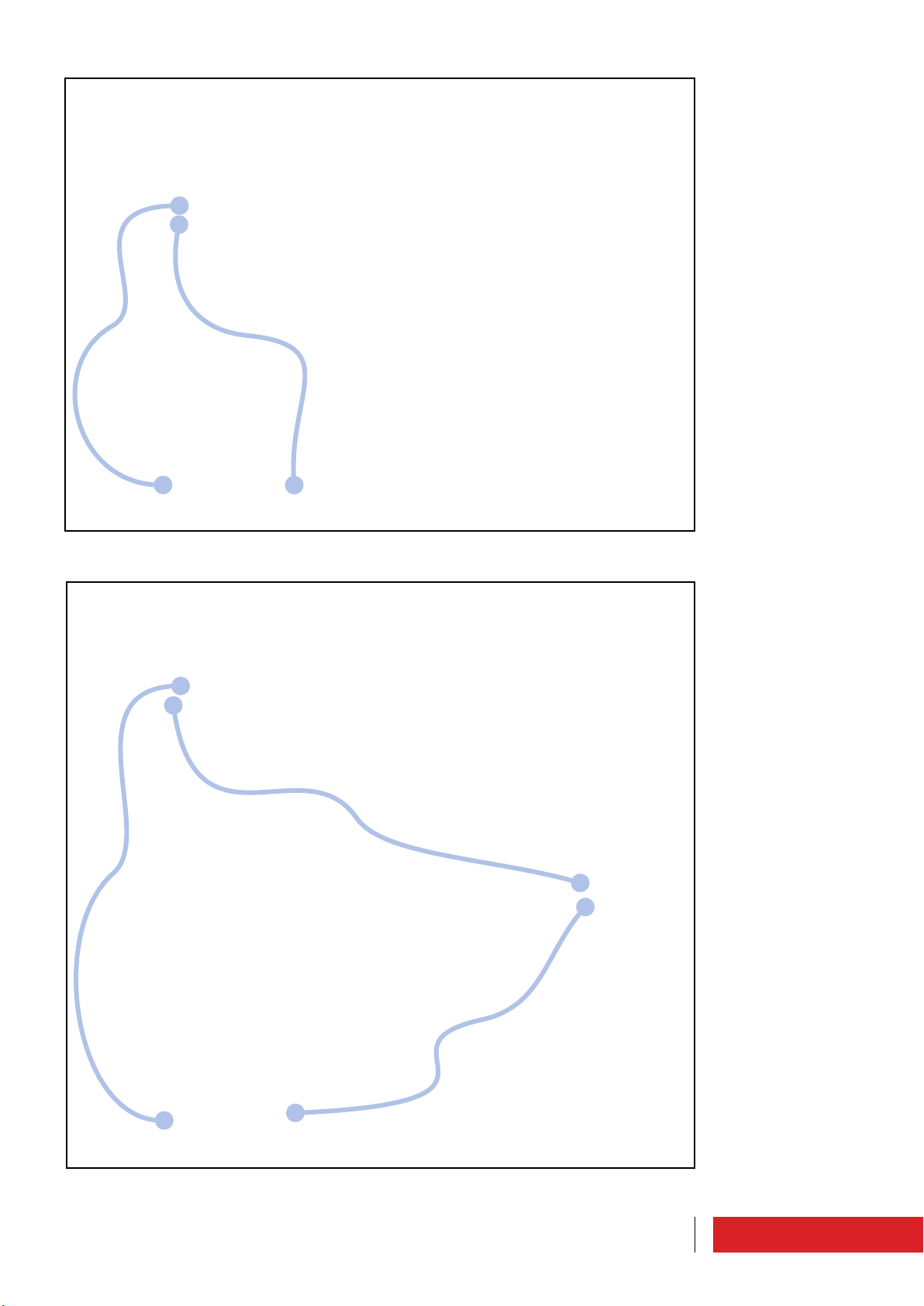
3.4.3 Exchange unit and/or audio matrix connection
This connection allows to use the transmitter in a system that exchanges a fault transmitter failed with a reserve.
To exchange unit connection, if the equipment is not a reserve, a shielded cable must
be inserted into “TC/TS”, DB25, on the rear panel of the machine.
If the device is a reserve to use an additional shielded cable to insert in “PROFILES” connector, DB25, in the rear panel of the machine.
This last cable will connect to the audio matrix, if there is an audio matrix.
These cables are shipped with the unit of exchange (Elenos code CAB0324-0).
The connection may be did also during running machine, but not the RF connection.
For more information, please see “Exchange unit” manual.
CAB0324-0
Exciter
Echos6
68
Use instructions
Page 36
CAB0324-0
Exciter
CAB0324-0
Echos6
Exciter
CAB0324-0
Matrix
CAB0324-0
CAB0324-0
Echos6
Use instructions
69
Page 37

3.4.4 Amplifier connection
This connection is to increase the power transmission using a RF power amplifier.
To use the ETG as an exciter of a higher power amplifier to connect the ETG RF output
connector to amplifier RF input connector through a RF coaxial cable, which is capable of
withstanding the maximum power of ETG (Elenos code depending on connector type).
In addition to the RF connection, should be included a cable to insert in TC/TS connector,
DB25, on the rear panel (Elenos code CAB0324-0).
This cable ships on demand and it’s important check exciter functionality of the in the
case of amplifier protection (eg exciter shutdown in case of ROS / VSWR amplifier protection).
To RF connection the machine must be turned off.
For more information, please see “Amplifier” manuals.
Exciter
CAB0324-0
Amplifier
70
Use instructions
Page 38

3.4.5 E.BOX module connection
Tale collegamento consente di avere un “ponte” tra il bus EIA485 dell’apparato e la rete
Ethernet.
To E.BOX connection a standard cable must be inserted into “EIA485” connector, DB9, on
the front or rear panel of the machine.
This cable is shipped withE.BOX (Elenos code ETGSAL33).
The connection may be did also during running machine.
For more information, please see “E.BOX” manuals.
Exciter
ETGSAL33
E.BOX
Use instructions
71
Page 39

72 Use instructions
Page 40
4 Maintenance
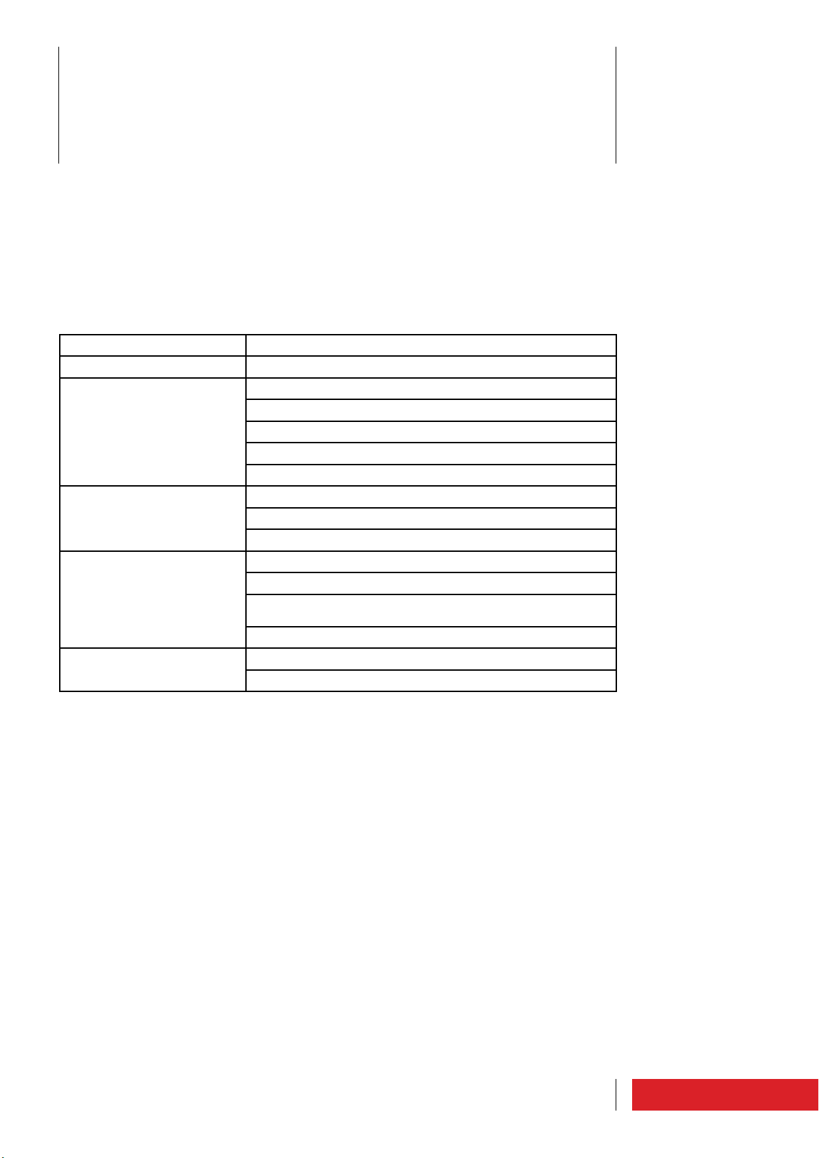
4.1 Maintenance (cleaning, replacement, control)
During normal operation periodic inspections are recommended, in order to verify the
absence of critical operating conditions.
It is recommended to adopt the following program:
Frequence Type of maintenance
15 days To clean filter (very dusty environment).
30 days
6 months
12 months
24 months
To clean filter (slightly dusty environment).
To check direct and reflected output power.
To verify telemetry, if present.
To verify RF modules.
To verify power supplies.
To verify fans.
To verify temperatures.
To verify electricity consumption.
To verify tightening of the RF output connector.
To verify mains connections.
To verify fan blades cleaning and the air grid (dusty environ-
ment). To be made with the unit in standby.
To wash filters (dusty environment).
To wash filters (slightly dusty environment).
To change filters (dusty environment).
Maintenance
73
Page 41

4.2 Malfunction (effects, causes and solutions)
Effect Cause Solution
Transmitter does not turn on • Power cord defective or
missing
• Auxiliary power incorrect (MAINS LED on front
panel off)
• Fault in power stage
• Replace the cable or connect to apparatus
• Call the manufacturer
• Call the manufacturer
Transmitter does not reach
the required power
Transmitter transmits on a
frequency different from
required frequence
No modulation in output and
on display
No modulation in output, but
displayed
• Transmitter in Stand By
• No interlock connection
(if TC/TS option)
• PLL not locked (ON AIR
LED on front panel off)
• Power supply fault
• RF module fault
• Measure point fault
• PLL board fault
• VCO board fault
• Absence or interruption
audio cables
• MPX board fault
• Stereo Coder board fault
• Modulation off
• MPX board fault
• Stereo Coder board fault
• Set the transmitter in RF
ON
• Connect interlock connection
• Call the manufacturer
• Call the manufacturer
• Call the manufacturer
• Call the manufacturer
• Call the manufacturer
• Call the manufacturer
• Connect or change audio
cables
• Call the manufacturer
• Call the manufacturer
• Activate modulation by
related menù
• Call the manufacturer
• Call the manufacturer
Modulation in output that not
reaches the desired value
No stereo modulation • Stereo carrier off
One or more fans stopped • Fans fault
• Low audio level input
• MPX board fault
• Absence or interruption
audio cables
• Stereo Coder board fault
• Absence Stereo Coder
board
• Fans power supply fault
• Increase source audio
level
• Increase ETG input sensitivity or call the manufacturer
• Turn on the stereo carrier
from the related menu
• Connect or change audio
cables
• Call the manufacturer
• Transmitter can not be
used for stereo broadcasts
• Call the manufacturer
• Call the manufacturer
74 Maintenance
Page 42

No communication with telemetria/PC
• Address incorrect
• Connection cable not
suitable
• Parameters setting incorrect
• Connection cable fault or
interrupted
• CPU board fault
• Set the correct address
• Verify that the cable used
is that provided by Elenos
or an equivalent
• Check correct parameters in “Use
instructions”section, “Optional equipment can be
connected”(user manual)
and to set them
• Connect or change cable
• Call the manufacturer
75Maintenance
Page 43

The manufacturer shall provide at the technical staff the spare parts manual and
the service manual.
These documents contain confidential design information, so if you need them
you must require in writing form Elenos s.r.l. autorization.
76 Maintenance
Page 44

APPENDIX USER MANUAL
ETG 2000.20
ETG 1500.15
ETG 1000.10
ETG 700.7
ETG 500.5
ETG 300.3
ETG 150
Page 45

0470
Operational headquarters : via G. Amendola 9, 44028 Poggio Renatico (Fe) ITALY
C.C.I.A.A. 101 216
Tax code and VAT reg. no. IT00415540384
Please contact Elenos technical support service for information and assistance:
Tel : +39 0532 829965
Fax : +39 0532 829177
E-mail : [email protected]
Website : www.elenos.com
Please provide the equipment serial number (indicated on the nameplate).
UNI EN ISO 9001:2008 certified company
Certificate No.102222A
Elenos s.r.l. declares that the equipment described in this document is compliant with the 1999/05/EC Directive.
For details please refer to the “EC Marking” section.
All rights reserved. No part of this manual can be reproduced in any form without prior written authorization from Elenos
S.r.l.
Page 46

Contents
1.1 Changes to software update.............................................................................................. 5
1.1.1 TX control panel .......................................................................................................... 7
1.1.2 Profile RF/Baseband mode ........................................................................................ 8
1.1.3 Profile baseband levels .............................................................................................. 8
1.1.4 View TX parameters 1 ................................................................................................ 9
1.1.5 View TX parameters 2 ................................................................................................ 9
1.1.6 Baseband levels ....................................................................................................... 10
1.1.7 Alarms list ................................................................................................................. 10
1.1.8 Events history ........................................................................................................... 10
1.1.9 Password................................................................................................................... 11
1.1.10 Password setting .................................................................................................... 11
1.1.11 Password recovery .................................................................................................. 11
1.1.12 System config ......................................................................................................... 12
1.1.12.1 Power oscillation algorithm ............................................................................ 12
1.1.12.2 Foldback algorithm ......................................................................................... 12
1.1.13 Audio trim & alrm ................................................................................................... 13
1.1.13.1 Audio “Disable” alarm ................................................................................... 13
1.1.13.2 “No audio” audio alarm ................................................................................. 13
1.1.13.3 “Swap” audio alarm ....................................................................................... 13
1.1.13.4 “Fault” audio alarm ....................................................................................... 13
1.1.13.5 “Flt/Swap” audio alarm ................................................................................ 13
1.1.14 Communication port set ......................................................................................... 14
1.1.15 System info ............................................................................................................. 14
1.1.16 System Time ........................................................................................................... 14
1.1.17 Clock Pwr Target ..................................................................................................... 15
1.1.18 Enable Alarms Sms ................................................................................................. 16
1.1.19 User Alarms Data .................................................................................................... 16
1.1.20 User Alarms Timers ................................................................................................ 17
1.1.21 Lifextender ............................................................................................................. 18
1.1.22 GSM and modem service ........................................................................................ 19
1.1.23 Phone N.1 to N.8 .................................................................................................... 19
Contents
3
Page 47

4 Contents
Page 48

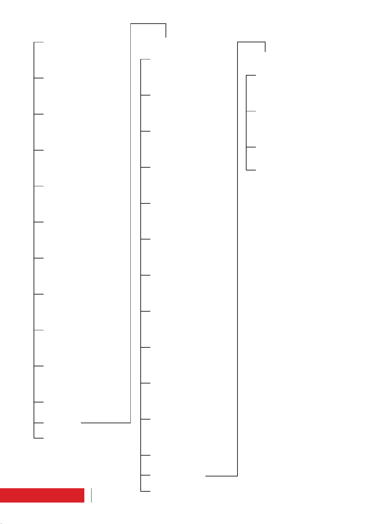
User interface
1.1 Changes to software update
The user interfaces described, and referred, in the quick start and user manuals
are related to the software version number to 2.41.
For software version greater than 2.41 interfaces are those described below.
Warning : The screen images shown here are only for illustrative purposes only, as well
as the values assigned to parameters. The parameters displayed may differ slightly depending on the type of machine and the type and settings of your stereo coder board.
User interface
5
Page 49
TX CONTROL PANEL
SYSTEM CONFIG
PROFILE RF/BASEBAND MODE
PROFILE BASEBAND LEVELS
VIEW TX PARAMETERS 1
VIEW TX PARAMETERS 2
BASEBAND LEVELS
GSM AND MODEM SERVICE
AUDIO TRIM & ALRM
PHONE N.1 TO 4
COMMUNICATION PORT SET
PHONE N.5 TO 8
SYSTEM INFO
EXIT
SYSTEM TIME
CLOCK PWR TARGET 1 OF 2
ALARMS LIST
EVENTS HISTORY
PASSWORD
PASSWORD SETTING
PASSWORD RECOVERY
CLOCK PWR TARGET 2 OF 2
ENABLE ALARMS SMS
DISPLAY ALARMS BIT
USER ALARMS DATA
USER ALARMS TIMERS
MENU SYSTEM
EXIT
6
User interface
LIFEXTENDER
MENU GSM/MODEM
EXIT
Page 50
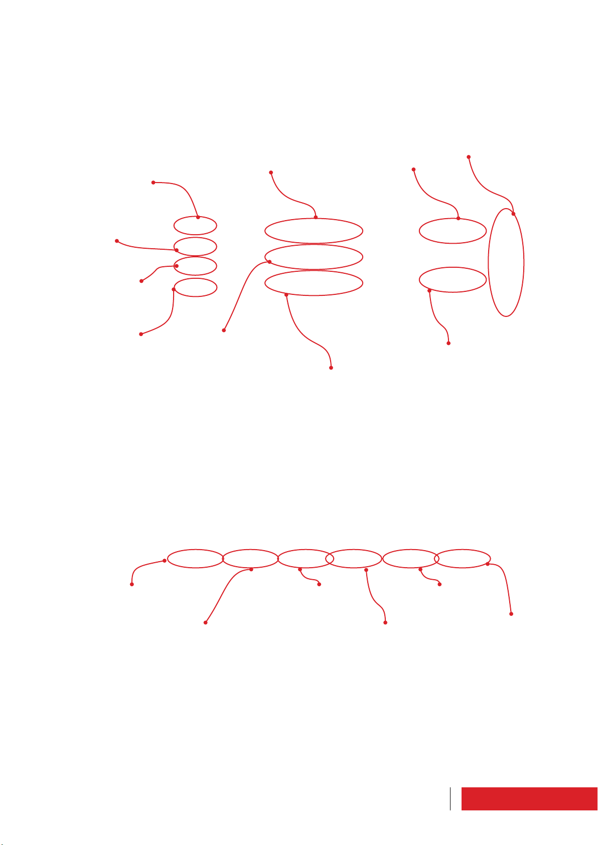
1.1.1 TX control panel
Main screen which appears automatically when turning on in LOCAL mode. It is used to
set and check the main operating parameters.
Warning light: when
it is on it indicates the
opening of the interlock
contacts.
Warning light: when it is
on it indicates a power
drop below 3dB (<50%
of target)
Warning light: when it is
on it indicates the clipper engagement caused
by overdrive
Target frequency
Target audio level
Vu-meter: it must
indicate approx. 0dB
Warning light: when it is on
it indicates an absence of
signal beyond the limits set
To access the list of
menus
Target power
To switch on /put the
system on stand-by
Forward power effectively delivered
To reset the
alarms
To set the pre-emphasis
level
Reflected power: it must
be null or very low
To set the audio
signal
To set the profile
7User interface
Page 51

1.1.2 Profile RF/Baseband mode
Setting and display screen.
For every profile, the frequency, target power, type of audio signal and pre-emphasis
are defined.
The active profile values are indicated by the letter “A”. The deviation is displayed (in
kHz).
1.1.3 Profile baseband levels
Setting and display screen.
For each profile, the audio signal level, auxiliary channel level (expressed as a percentage, 100% equals the maximum amplitude for 75kHz deviation), clipping value and
reference voltage value are defined.
The active profile values are indicated by the letter “A”. The deviation is displayed (in
kHz).
8 User interface
Page 52
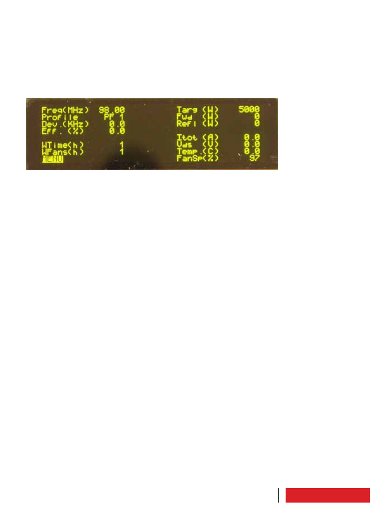
1.1.4 View TX parameters 1
Display only screen.
The parameters which can be monitored are as follows: frequency, active profile number, deviation, efficiency, transmitter working hours, fan working hours, direct power
target, effective direct power value, reflected power, current, voltage, maximum temperature (the following pictures show the probe position) and fan speed.
1.1.5 View TX parameters 2
Display only screen.
The parameters which can be monitored are as follows: current and temperature of the
amplifier modules, current, voltage and temperature of the power supplies, voltages
and auxiliary power supply polarization, sum of the power supply currents, sum of the
module currents, voltage, ambient temperature and efficiency.
9User interface
Page 53

1.1.6 Baseband levels
Setting and display screen.
There are levels of the audio signal.
The display changes depending on the audio mode selected.
1.1.7 Alarms list
Display only screen.
It is possible to monitor the list of most recent alarms. The alarms indicated by the letter “A” are still active.
In order to understand the meaning of the alarms, please refer to paragraph “Alarms/
events list”.
1.1.8 Events history
Display only screen.
The log of all the events/alarms occurred (up to 99) can be monitored. These are indicated by code, description, date and time.
10 User interface
Page 54
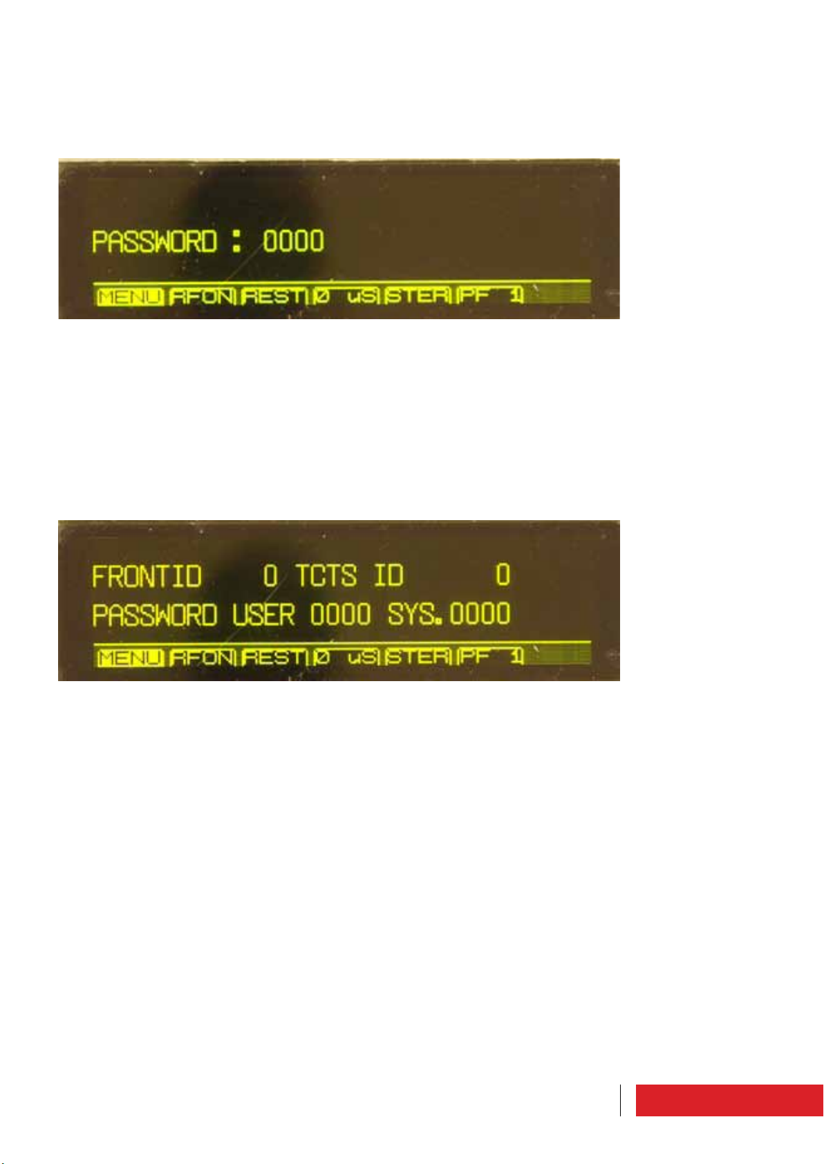
1.1.9 Password
The equipment is delivered with the default password “0000” that can be customized
by the user (for more details, please see paragraph “Password Setting”).
In this screen the access password must be entered.
1.1.10 Password setting
There are two levels of user privilege: USER and SYSTEM, which are both initially protected by the default password “0000”.
In this screen it is possible to define customized passwords by the user with “SYSTEM”
privileges.
Other parameters that can be set from this menu are the machine addresses (reference
for communication with it).
1.1.11 Password recovery
If you lose your password, please contact Elenos.
Elenos must be given the “Unlock code” in this screen.
Elenos will provide a password valid for 24 hours to be entered on the same screen
under the “Password Recovery” item.
The user must later define new passwords through the “Password Setting” screen.
11User interface
Page 55

1.1.12 System config
Setting and display screen.
The following parameters can be set by the user: temperature measurement unit
(Temp. U.), remote display operating mode (Show D.), audio board model (BB model,
automatically detected, or STEREO view as default), equipment protection in case of
oscillations (PwOscChk), power target when working with a UPS (UPS T), VCO synchronization (Time base, internal or external
at 10MHz), power reading calibration (FwdPwrCal), SWR foldback, polarization threshold
(IPA Bias Tres.), reflected power nominal threshold (Refl.Pwr T.N., when active it is
10% of direct power), reflected power customized threshold (Refl.Pwr T.Lev., when the
nominal threshold is inactive, it is possible to set values below10%), final polarization
(PAbias), maximum settable power full scale (Max Target Pwr).
1.1.12.1 Power oscillation algorithm
In Elenos devices, if there is a power variation of “n” W (“n” being defined in specific
tables) at least 3 consecutive times within 15 seconds, the “035” alarm is activated and
the three block out mechanism is triggered (if this mechanism fails, the “003” alarm is
then activated).
1.1.12.2 Foldback algorithm
The Elenos devices feature two different and independent protections which are activated when there is an excess of reflected power.
The first is a hardware threshold which operates when the reflected power exceeds
10% of the maximum rated output power of the transmitter in a very short space of
time.
In these conditions the transmitter switches off.
The second is a software protection, called “foldback algorithm”.
It is activated when the reflected power increase is slower (for example, when there is
snow or ice on the antenna).
In these conditions, the transmitter gradually reduces its output power until the reflected power threshold is exceeded, while the output power is gradually restored when
the values go back to normal.
If normal operating conditions continue for more than 60 seconds, the algorithm is
inactive.
The activation of this second protection is left to the user (from the
System config screen).
12 User interface
Page 56

1.1.13 Audio trim & alrm
Setting and display screen.
The following parameters can be set by the user: pilot tone level, pilot tone phase,
clipping voltage.
It is possible to monitor the audio board model (BB board model, automatically
detected, or STEREO view as default) and the firmware version of the audio board (BB
Firmware).
The alarms connected to the audio section are set. The management uses the TC/TS
connector.
The alarm is activated when it is below the threshold set (Modulation), after the set
period of time (Dlay Alarm Timer).
The user can choose from five operating modes (Bad mod.) : DISABLE, NO AUDIO, SWAP,
FAULT, FLT/SWAP.
1.1.13.1 Audio “Disable” alarm
By setting the “Bad mod.” field to “DISABLE”, the alarm is completely deactivated without needing to change the levels (Modulation, Dlay Alarm Timer).
1.1.13.2 “No audio” audio alarm
By setting the “Bad mod.” field to “NO AUDIO”, the default setting is kept, i.e. “No Audio” on pin 23 of the TC/TS connector.
If the transmitter is inside an N+1 system, the “No Audio” signal is not available at the
exchange unit.
1.1.13.3 “Swap” audio alarm
By setting the “Bad mod.” field to “SWAP”, the “No Audio” line (pin 23) is exchanged
with the “Warning” line (pin 13) on the TC/TS connector.
If the transmitter is inside an N+1 system, the “No Audio” signal is available at the
exchange unit.
1.1.13.4 “Fault” audio alarm
By setting the “Bad mod.” field to “FAULT”, the “No Audio” line (pin 23) is in “or” condition with the “Fault” line (pin 24) on the TC/TS connector.
If the transmitter is inside an N+1 system, the exchange unit activates the switching in
the presence of No Audio.
1.1.13.5 “Flt/Swap” audio alarm
By setting the “Bad mod.” field to “FLT/SWAP”, there is a combination of the two
“Swap” and “Fault” modes.
In this way, if the transmitter is inside an N+1 system, the “No Audio” signal is available
at the exchange unit and the exchange unit actives the switching.
13User interface
Page 57
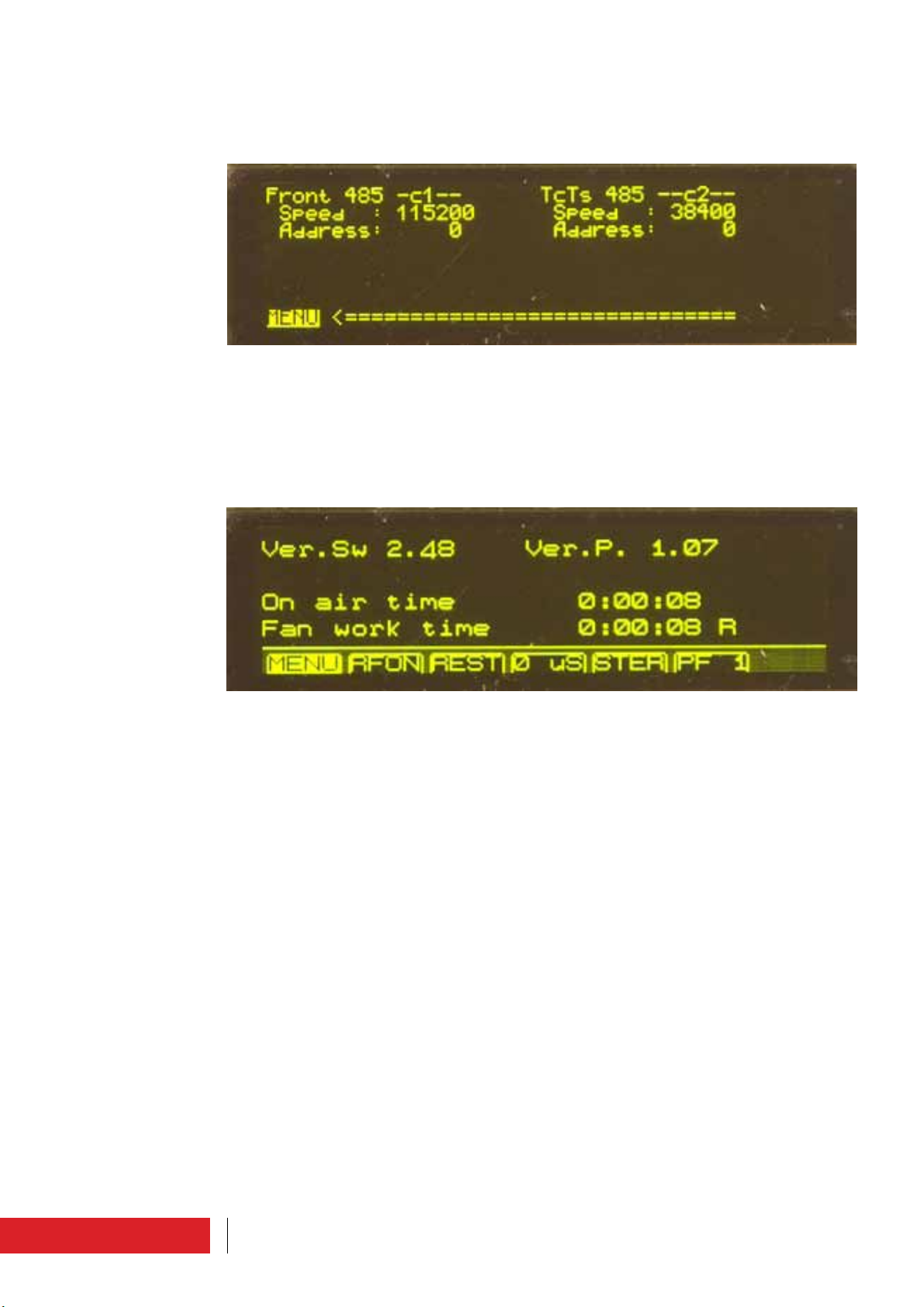
1.1.14 Communication port set
Setting and display screen.
The parameters which can be set by the user are the speed and the front and rear 485
door addresses.
1.1.15 System info
Setting and display screen.
The equipment software version, the protocol version, the equipment activity time and
the fan operating time are indicated.
It is possible to reset the latter by clicking “R”.
1.1.16 System Time
Setting and display screen.
The following parameters can be set by the user: the day of the week, date and time.
14 User interface
Page 58

1.1.17 Clock Pwr Target
Setting and display screen.
As well as the standard power adjustment, it can also be set according to time slots in
order to save energy. In order to be able to set the power according to individual time
slots, the field “Target Power Mode” must be set to “CLOCKED”.
Then, the various times of day can be matched with four different power percentage
values (100%, 75%, 50% or 25% of the set power).
After defining the day of the week to be set (Target Power on day of) for each time of
day, press the cursor to enter the setting bar, rotate it to define the percentage (nothing
displayed corresponds to 25%, T1 corresponds to 50%, T2 corresponds to 75%, T3 corresponds to 100%) and press the cursor to confirm.
By setting the “Copy over next day” field to “T”, the previous day setting is copied to
the next day.
By setting the “Reset at default” field to “T”, the settings are reset to default, where
the power is low at night and full during the day.
15User interface
Page 59

1.1.18 Enable Alarms Sms
Setting and display screen.
Besides the alarm management “by status”, it is possible to have
alarm management “by event”.
The alarms for which this management mode is enabled merge in a buffer.
If the value “0” is attributed to the relative alarm, it means that is deactivated, while
the value
“1” means that is activated to be managed in “by event” mode.
This function is available only by means of connection on the Omron protocol.
In order to understand the meaning of the alarms, please refer to paragraph “Alarms/
events list”.
1.1.19 User Alarms Data
Setting and display screen.
Some alarms can be set according to activation conditions.
The current value of the alarm condition parameter (ambient temperature, RF temperature, RF current, power supply temperature, power supply current, direct power, reflected power) can be monitored.
By setting the “En.” parameter to “T/F” the respective alarm is enabled/disabled.
The following parameters can be set by the user: the parameter minimum and maximum values, and the type of condition to be met (upper, lower, inside, outside).
16 User interface
Page 60

1.1.20 User Alarms Timers
Setting and display screen.
In some alarms, it is possible to set a time frame in which the condition must occur in
order to make the alarm effective (“Dlay”).
The trend of the meter for this time can be monitored as well as the possible enabling
of the alarm by means of a status flag (Alrm).
17User interface
Page 61

1.1.21 Lifextender
Setting and display screen.
The parameters relative to the Lifextender option can be monitored: equipment serial
number, equipment code (parameter to be notified to Elenos should the user require
the activation/deactivation of this function), activation/deactivation code (parameter
supplied by Elenos to be entered for the function activation/deactivation), function status, work days in good operating conditions, work days in critical operating conditions.
The algorithm considers the following parameters to define the critical days: RF temperature, power supply temperature, ambient temperature and reflected power with
respect to maximum operating power.
These parameters must exceed the threshold values for a certain amount of time.
In this way, the duration and intensity of the event is assessed: intense short events are
heavy; less intense but longer events are heavy too.
18 User interface
Page 62
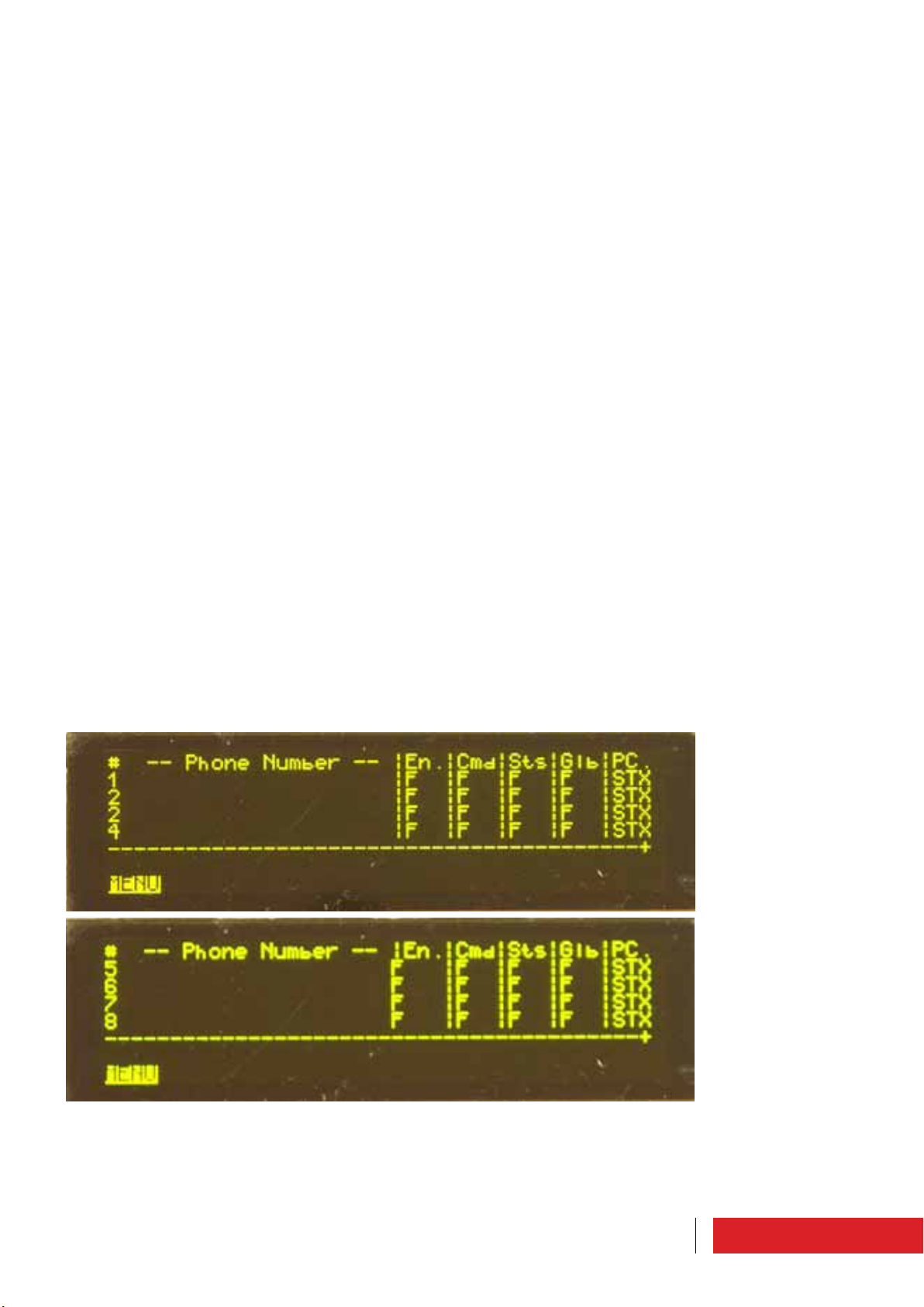
1.1.22 GSM and modem service
Setting and display screen.
The GSM signal field intensity can be monitored.
It is possible to enable the submission of an alarm by SMS and/or PSTN in case of no
mains power (No Mains SMS) for the period of time set (Delay).
It is possible to enable the submission of an alarm by SMS and/or PSTN if the power
delivered is at least 3dB less than the target set (SMS FWD over 2/3).
The codes to be displayed in the different message strings can be defined (PagerId,
StatId, String Id).
1.1.23 Phone N.1 to N.8
Setting and display screen.
The equipment can “communicate” with up to 8 SIM cards.
The telephone numbers and authorizations can be defined in international format
The number can be globally enabled for SMS transmission and reception SMS (En.), be
enabled to send commands (Cmd), be enabled to request and receive the machine status (Sts), be enabled to receive the echo any of commands sent by other numbers (Glb)
and be enabled to receive SMSs in text or digital format (PC.).
19User interface
Page 63

20 User interface
 Loading...