

Page 1
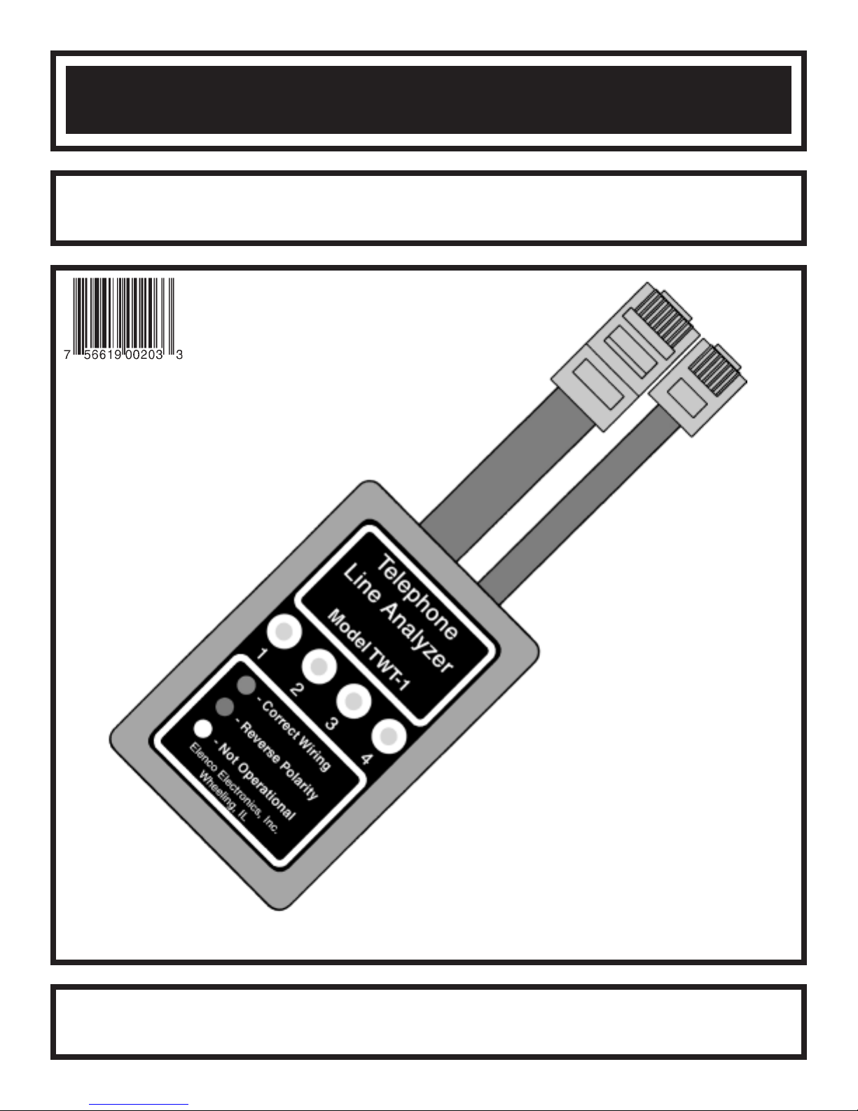
TELEPHONE LINE ANALYZER
MODEL TWT-1
Elenco Electronics, Inc.
Copyright © 2001 Elenco Electronics, Inc. 753282
Instruction Manual
Page 2
SPECIFICATIONS
CATEGORY OF WALL PLATE JACKS
• Standard RJ-11 modular jacks with active telephone lines (one or two lines).
• Standard RJ-45 modular jacks with active telephone lines (one to four lines) for configuration EIA/TIA 568A
or B, AT&T 258A, token ring, or 10 BASE-T.
MULTIPLY FUNCTIONS
• Polarity identify (straight or reverse) cable and/or pairs.
• Open or short wiring test.
ENVIRONMENTAL CONDITIONS
• Indoor Use • Operating Temperature: 5OC to 40OC / 41OF to 104OF
• Altitude up to 2,000M • Storage Temperature: -40OC to 60OC / -40OF to 140OF
• Pollution Degree: 2 • Relative Humidity: 0% to 90% (0OC / 32OF to 35OC / 95OF)
INTRODUCTION
The TWT-1 Telephone Line Analyzer has been designed to test telephone wall plates using RJ-11 and RJ-45
jacks. The most common jack used in homes, offices, or commercial establishments is the RJ-11. It is designed
to connect up to three telephone lines. However, it is most common to have one or two lines connected to the
jack. Your TWT-1 Tester will test up to two lines on an RJ-11 jack or up to four lines on an RJ-45 jack.
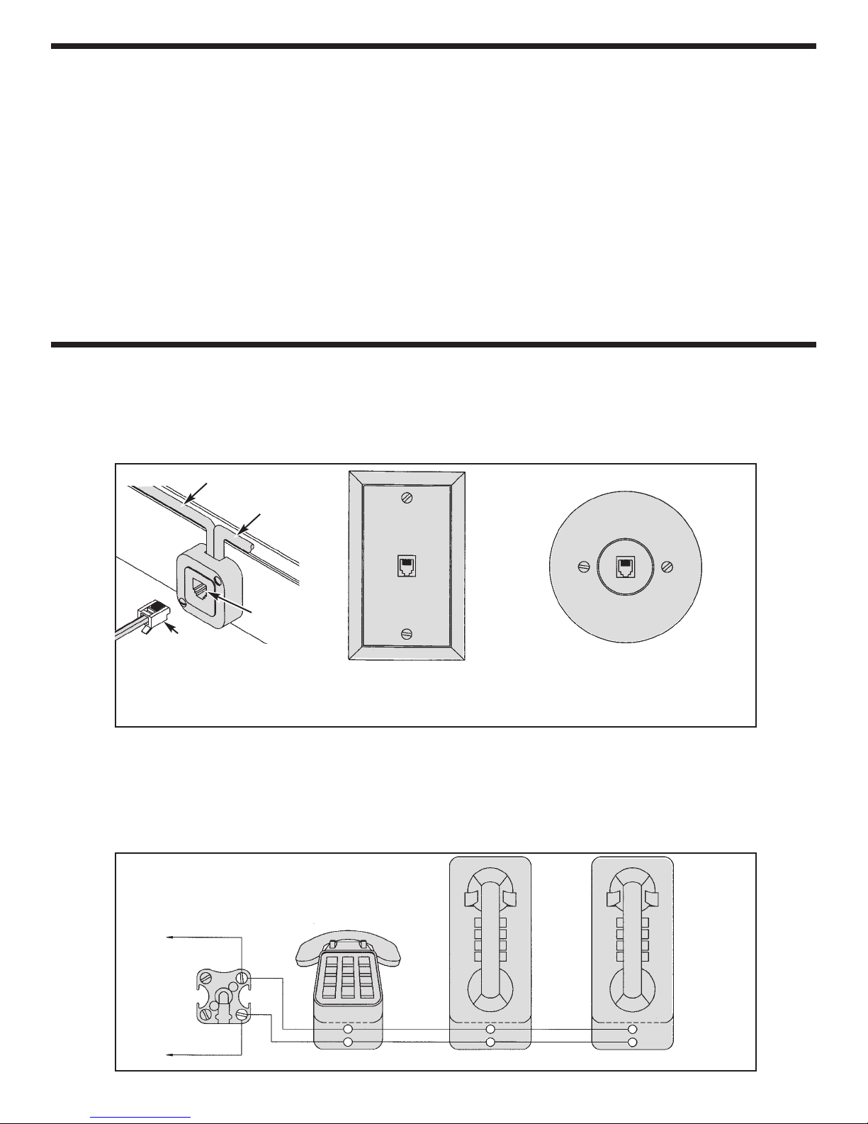
Line from outside
To other phones
Modular
Plug
Figure 1
Surface Mounting
Modular Jack
Jack
Figure 2
Wall Plate Using RJ-11 or
RJ-45 Jacks (Modular Outlet)
Figure 3
Another Type of Wall Plate Using
RJ-11 Jack (Modular Outlet)
When testing a wall plate using an RJ-11 in a home, keep in mind that the single line may have multiple phones
connected. Figure 4 shows a home or office with three phones connected to a single incoming line. Note they
are in parallel. The 42A block, shown in Figure 4, is where your telephone lines start in your home or office.
The 42A block may have terminals marked “R”’ and ”‘T”. “R” stands for Ring and “T” stands for Tip. If correct
wiring procedures were followed, then red goes to “R” ring and green goes to “T” tip. Color code terminations
should be followed at all wall plates.
Figure 4
Multiple Phones Connected to a Single Line
R
Single Line
To Protector
42A
Red
T
Green
-1-
Wall
WallDesk
Page 3
HOW IT WORKS
The TWT-1 Analyzer is easy to use in quick testing
of the telephone lines. It will indicate by the color of
the LED if the wiring is correct, reversed or if it is not
working at all.
WIRING CONFIGURATION
for RJ-11 JACKS
Figure 6
Typical color
RJ-11-2 RJ-11-4
1 6
scheme for one or
two lines.
1 6
Figure 5
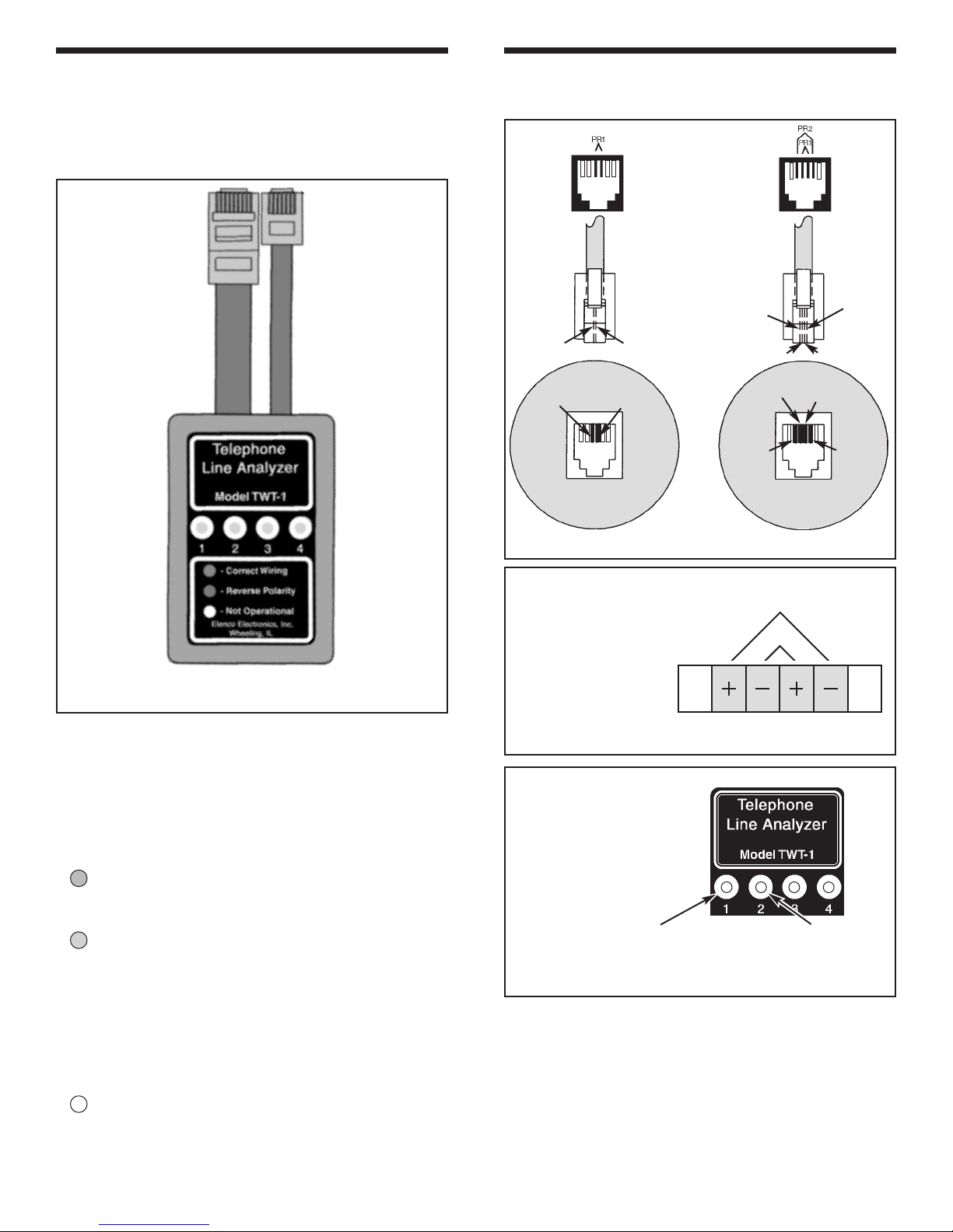
It has four bi-colored LEDs that will light green or
red. LEDs 1 and 2 will respond to testing of an
RJ-11 jack having one or two lines. LEDs 1, 2, 3
and 4 will respond to testing of an RJ-45 jack
having one, two, three, or four lines using a wiring
scheme (see Figure 9).
Green LED is Lit - Indicates that the line
tested is operational and the wiring is correct.
Yellow
Green
Green
Yellow
Red
Red
Green
Green
Black
Red
Red
Black
RJ-11 Jack RJ-11 Jack
One Phone Line Two Phone Lines
Figure 7
Shows detail of how
the tip and ring are
connected on a four
connector cable.
+ = Tip
_
= Ring
Plug Polarities
O
P
E
N
2
3
PR2
PR1
4
5
Figure 8
Shows how the
phone wires relate
to the LEDs on the
analyzer for RJ-11.
O
P
E
N
61
Red LED is Lit - Indicates that the wiring to
the jack is reversed. On some phones, it
would make the phone inoperative and would
require a reversal of the wires terminating at
the phone jack. On many new phones, the
phone circuitry recognizes this reversal and
corrects for it.
No LED Lit - Indicates that the circuit is not
operational (open or shorted).
PR 1
Wires 3 and 4
Wires 2 and 5
When we refer to an RJ-11 plug and jack, we are
generally referring to a single or dual line plug and
jack. In the industry they may sometimes refer to an
RJ-11-2 as a single line jack and an RJ-11-4 as a
two line jack. Most modular jacks today are prewired with four wires and are suitable for one or two
lines. From the face of the wall plate, it is difficult to
tell if it’s wired for one or two lines.
-2-
PR 2
Page 4

WIRING CONFIGURATIONS
FOR RJ-45 JACKS
The RJ-45 indicates an 8-wire plug or jack. There
are many standards which dictate which wire pairs
connect to which pins on a plug or jack. Some of
these standards are listed below.
Figure 10
Typical color
scheme for eight
lines.
1 8
EIA/TIA-568A
EIA/TIA-568A
EIA/TIA 568B
or AT&T 258A
Token Ring 10 Base T
Figure 9
Different Wiring Standards for RJ-45 8-Wire Jacks
Red
Black
Blue
Orange
Orange
Blue
Black
Red
Green
Yellow
Gray
Brown
Brown
Gray
Yellow
Green
RJ-45 Jack
Figure 11
Shows detail of how the tip and ring are connected on
a eight connector cable for EIA/TIA-568A standards
on Figure 9.
PR3 PR4
PR2
PR1
The telephone line analyzer TWT-1 is designed to
test the standard configurations shown in Figure 9.
The Electronic Industries Association established
this sequence as a “commercial building
specification”.
Shown below are the wire color codes for an
EIA/TIA-568A, shown in Figure 9.
White / Green
T
3
R3Green / White
T2White / Orange
R1Blue / White
T1White / Blue
R
Orange / White
2
T4White / Brown
R4Brown / White
2
1
Plug
Polarities
+ = Tip
_
3
= Ring
4
5
6
7
8
Figure 12
Shows how the phone wires relate to the LEDs on
the analyzer for EIA/TIA-568A.
PR 1
Wires 4 and 5
PR 2
Wires 3 and 6
PR 4
Wires 7 and 8
PR 3
Wires 1 and 2
-3-
Page 5

! !
CAUTION
Test only standard telephone circuits. DO NOT connect to power sources with sustained voltages greater than 15 volts
@ 50 milliamperes.
USING THE TELEPHONE LINE ANALYZER ON RJ-11 JACKS
The telephone line analyzer is designed to test RJ-11 jacks having one or two lines connected. This is the
most common hook up in homes and commercial establishments. If wall plates with RJ-11 are not available,
then (for testing and demonstration) you should use the telephone line simulator Model TT-250 (Figure 20).
It will provide all of the conditions that would be found in the field and are illustrated below.
The following is the procedure for testing a typical
one line RJ-11 jack:
1. Remove the phone wire from the
modular jack and insert the
smaller telephone plug of the
telephone line analyzer into the
telephone jack to be tested.
If the telephone line analyzer shows
2.
Green
LED 1 green, the telephone line
jack is working and it is wired with
straight polarity (see Figure 13).
The problem is in the telephone
cable going to the telephone or in
the telephone itself. The wiring in
the wall jack is correct.
DO NOT CALL THE
TELEPHONE COMPANY.
Figure 13
3. If the telephone line analyzer
shows LED 1 red (see Figure 14),
the modular jack is working with
reversed polarity. The wires are
reversed. A dial tone should still
exist, but this may be a problem
Red
for some touch phones. Plug the
phone back into the wall jack and
lift the receiver. If a dial tone is
present, but you do not get tones
when dialing, the wiring at the wall
jack should be corrected. See
technical data for wall jack wiring.
The following is the procedure for testing a typical
two line RJ-11 jack:
1. Remove the phone wire from the
modular jack and insert the
smaller telephone plug of the
telephone line analyzer into the
telephone jack to be tested.
2. LEDs 1 and 2 green (see Figure
16) indicates that both lines are
1 and 2
Green
working and are wired straight
polarity. The problem is in the
cable going to the phone or in the
telephone.
Figure 16
3. LEDs 1 and 2 red (see Figure 17)
indicates both lines are working
with reversed polarity. The wires
are reversed on both lines and
may be a problem. Plug the
phone into the wall jack and lift
the receiver. If a dial tone is
present, but you do not get tones
1 and 2
Red
when dialing, the wiring at the wall
jack should be corrected. See
technical data for wall jack wiring.
Figure 14
4. If the telephone line analyzer
shows LED 1 with no light (see
Figure 15), it indicates that the
line is open or wires are shorted.
Check the wall jack to make sure
a wire is not bent too far down,
No Light
broken, or touching another wire.
If the problem is not in the jack,
then you may need to call the
telephone company.
Figure 15
-4-
1 Green
2 Red
Figure 17
4. LED 1 green and LED 2 red (see
Figure 18) indicates that line 1 is
wired with straight polarity and
line 2 is reversed polarity.
5. LED 1 no light, LED 2 green or
red. Line one is not operational.
6. LED 1 green or red, LED 2 no
light. Line two is not operational.
Figure 18
Page 6

USING THE TELEPHONE LINE ANALYZER ON RJ-45 JACKS
When testing an RJ-45 jack and there are two lines coming into the jack, two LEDs will be lit. If you have four
lines coming into the jack, four LEDs will be lit. If wall plates with RJ-45 jacks are not available, then
and demonstration) you should use the telephone line simulator Model TT-250 (Figure 20)
. It will provide all
of the conditions that would be found in the field and are illustrated below.
Before testing, you should know which wiring standard is coming into the jack.
TIA-568B or
EIA/TIA-568A
AT&T 258A
Token Ring 10 Base T
(for testing
Pair 1
Pair 2
Pair 3
Pair 4
Pair 1
Pair 3
Pair 2
Pair 4
Pair 1
Pair 2
Pair 2
Pair 1
Figure 19
The number pairs match with the number of LEDs on the label of the analyzer for EIA/TIA-568A and Token Ring
Y (see Figure 19).
ONL
The following is the procedure for testing RJ-45 jacks (for EIA/TIA-568A):
1. Remove the phone wire from the modular jack and insert the bigger telephone plug of the telephone line
analyzer into the telephone jack to be tested.
If the telephone line analyzer shows all green lights, the modular jack is working with straight polarity of all pairs.
2.
3. If the telephone line analyzer shows all red lights, the modular jack is working with reverse polarity of all pairs.
4. If you have mixed colors of lights, or some lights are not lit, you may have a problem.
No light indicates an open pair, a pair not being used, or shorted wires.
5. For example, if LED 2 is not lit, but LEDs 1, 3 and 4 are green, line 2 (pair 2 for EIA/TIA-568A) is defective.
Pair 2 is wire 3 (T
white / orange) and wire 6 (R2orange / white).
2
Telephone Line Simulator
Model TT-250
Test and demonstrate the usage of the TWT-1 Telephone
Line Analyzer. Simulate typical telephone line problems.
Figure 20
-5-
Page 7

LEARNING TO USE THE TWT-1 TELEPHONE LINE SIMULATOR MODEL TT-250
Elenco Electronics has developed a telephone line simulator, Model TT-250 (see Figure 20), for the TWT-1
Telephone Line Analyzer. It will simulate the most common field situations. It provides an RJ-11 jack for one or
two line testing, straight and reversed wiring and simulates opens.
It also provides an RJ-45 jack for one, two, three, or four line testing, straight and reversed wiring and simulates opens.
Contact Elenco Electronics (800) 533-2441 for availability and price of the telephone line simulator Model TT-250.
A great teaching tool for the telecommunication field.
If the
simulator
jack that has a phone connected to it. Remove the telephone line plug from the wall plate jack. Establish that it
is an RJ-11 or RJ-45 type jack, and insert the correct plug into the wall plate jack. If you know that it is a single
line phone, number 1 on the line analyzer should be lit green. If it is lit red, the wires are reversed. The phone
could still work because the phone has a circuit built into it to reverse it to the proper polarity.
If you know where there are wall plate jacks with more than one line coming in, then test that wall plate so that
you get familiar with normal readings.
DO NOT LEAVE THE TELEPHONE LINE ANALYZER IN THE JACK FOR ANY LENGTH OF TIME, AS THAT
LINE WILL GIVE A BUSY SIGNAL AND COULD OVERHEAT THE UNIT.
Model TT-250 is not available for testing and troubleshooting the TWT-1, you can use a wall plate
GENERAL MAINTENANCE
To clean, wipe the case with a damp cloth and detergent (do not use abrasives or solvents).
HOW THE CIRCUIT WORKS
The telephone line analyzer has four identical
indicators of polarity input voltage. Every indicator
includes two resistors and bi-color light emitting
diodes (LED), see Figure 21.
A
C
Ra Rb
Figure 21
The operation of the bi-color LED is very simple. This
LED has two standard LEDs inside with red and
green colors. When voltage on the anode (A) of the
first single color LED is higher than the voltage on the
cathode (C), current flows through this LED and it will
emit light. At the same time, other single LEDs will
not light. After changing the polarity of the voltage,
the second LED will emit light.
C Green
A Red
SCHEMATIC DIAGRAM
The resistor Rb limits the current so that the LED will
not be damaged. The normal open telephone line
voltage between the tip and ring wires is 48VDC.
The resistors Ra and Rb divide an input voltage to a
lower voltage that the telephone line has when
connecting the telephone to the loop.
Figure 22
-6-
Page 8

WORD GLOSSARY
42A Block A terminal block that provides telephone line junctions.
Bi-Color LED A component that combines two dice of different colors upon a single substrate or lead-frame
carrier.
Dial Tone A 350 and 440 hertz tone that is imposed on the line when the phone is first taken off the hook.
Diode An electronic component that rectifies AC to DC. Used for signal detection.
E.I.A. Standard T568A
E.I.A. Standard
T568B or AT&T 258A
FCC Federal Communications Commission. A U.S. Government agency that regulates and monitors
Ground An electrical connection to the earth of the a common conductor which is connected to the earth.
Hertz The basic unit for frequency or cycles per second.
LED (Light Emitting Diode) A semiconductor diode emitting incoherent light at its P-N junction when
Modular Cable A telephone cable with modular plugs used to connect phones or devices to the system.
Modular Jack The female connector of a telephone outlet.
Modular Plug The male connector that plugs into a modular jack.
PC Board Printed Circuit Board that has copper traces for conducting circuits to components.
Polarity Refers to positive (+) and negative (-) poles of a voltage source.
Positive The plus (+) pole of a battery DC supply or other polarity-sensitive item.
Pulse A short signal.
Ring The name of one conductor of a telephone line pair, identified by R. Most often the red wire and
RJ-11 A designation given to modular plugs and jacks capable of handling 1 to 3 phone lines.
RJ-45 A designation given to modular plugs and jacks, similar to an RJ-11, but larger and capable of
TelCo Abbreviation for telephone company.
Tip The name of one conductor of a telephone line pair, identified by T. Most often the green wire and
USOC A universal service code derived from Bell System specifications.
USOC 4 Refers to two pairs or lines on an RJ-11 jack.
The Electronic Industries Association established this sequence as a “commercial building
specification”.
Designed for data transmission.
the domestic use of the electromagnetic spectrum for communications.
forward biased.
the most negative of the two wires.
handling 1 to 4 lines.
the most positive of the two wires.
Your telephone line analyzer has been tested and conforms to our rigid requirements on performance and durability. It is guaranteed to be
free of defects in workmanship, materials and construction for a period of 2 years. If this product should fail during normal use within the
first 3 months from the date of purchase, Elenco will repair or replace the unit at no cost. For the remainder of the warranty period, a nominal
service charge is required to cover shipping and handling.
When returning merchandise for repair, please include proof of purchase, a brief letter of explanation of problem and sufficient packing
material. Before returning any merchandise, please call our service department at (847) 541-3800 to obtain a return authorization number
(RA).
Elenco Electronics, Inc. Service Department
150 W. Carpenter Avenue Wheeling, IL 60090
150 W. Carpenter Avenue • Wheeling, IL 60090 • (847) 541-3800
http://www.elenco.com • e-mail: elenco@elenco.com
WARRANTY POLICY
Elenco Electronics, Inc.
 Loading...