

Page 1
Elenco Electronics Inc.
Instruction Manual
Model TTPG-770
Tone aand PProbe
Copyright © 2001 Elenco Electronics Inc.
WWAARRRRAANNTTYY,, LLIIMMIITTEEDD RREEMMEEDDYY,, LLIIMMIITTEEDD
LLIIAABBIILLIITTYY::
This product will be free from defects in
material and manufacture for a period of one year from
the date of purchase.
EElleennccoo MMAAKKEESS NNOO OOTTHHEERR WWAARR-
RRAANNTTIIEESS IINNCCLLUUDDIINNGG,, BBUUTT NNOOTT LLIIMMIITTEEDD TTOO,, AANNYY
IIMMPPLLIIEEDD WWAARRRRAANNTTYY OOFF MMEERRCCHHAANNTTAABBIILLIITTYY OORR
FFIITTNNEESSSS FFOORR AA PPAARRTTIICCUULLAARR PPUURRPPOOSSEE..
If this product
is defective within the warranty period stated above, your
exclusive remedy shall be, at Elenco's option, to replace
or repair the Elenco product or refund the purchase price
of the Elenco product.
EExxcceepptt wwhheerree pprroohhiibbiitteedd bbyy llaaww,, EElleennccoo wwiillll nnoott bbee lliiaabbllee ffoorr
aannyy lloossss oorr ddaammaaggee aarriissiinngg ffrroomm tthhiiss EElleennccoo pprroodduucctt,, wwhheetthheerr
ddiirreecctt,, iinnddiirreecctt,, ssppeecciiaall,, iinncciiddeennttaall oorr ccoonnsseeqquueennttiiaall rreeggaarrddlleessss
ooff tthhee lleeggaall tthheeoorryy aasssseerrtteedd..
Made in China.
Elenco Electronics Inc.
150 W. Carpenter Av e .
Wheeling, IL 60090
(847) 541-3800
Fax: (847) 520-0085
http://www.elenco.com
For questions or product ordering information
contact customer service at 1-847-541-3800.
Page 2
1 6
Introduction
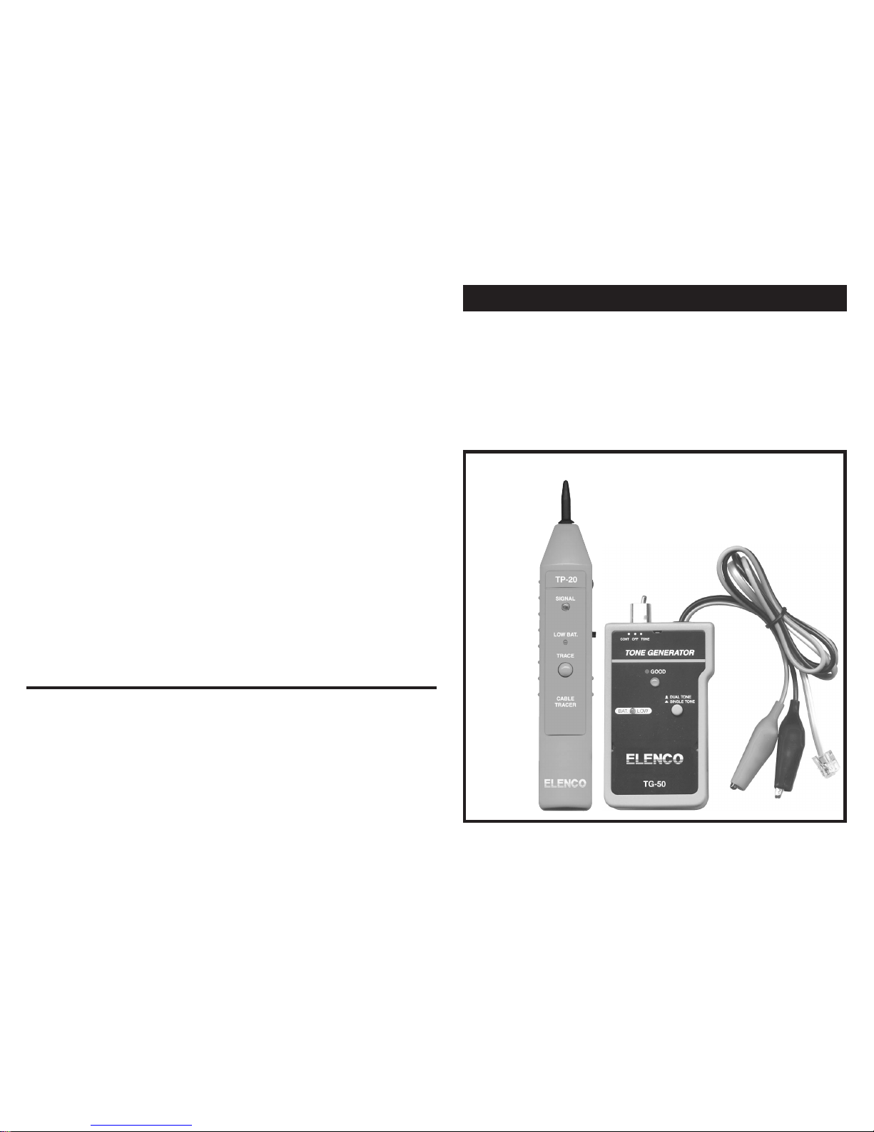
The model TG-50 Tone Generator is a highly practical
network installation and troubleshooting tool which features a single or multi-tone signal, two test leads and a
4-conductor modular cable. The signal emitted by the
Tone Generator can be easily traced by the Probe, even
when cables are bundled or hidden in a punch down
block or wall plate. The Tone Generator & Probe can be
used to verify cable continuity, identify wiring faults,
determine line polarity and voltage in network (CAT 5
and Coax) and modular telephone lines. The TP-20
Probe is equipped with a tone amplifier and an LED indicator that detects audible frequency tones for accurate
tracing and identification of wires.
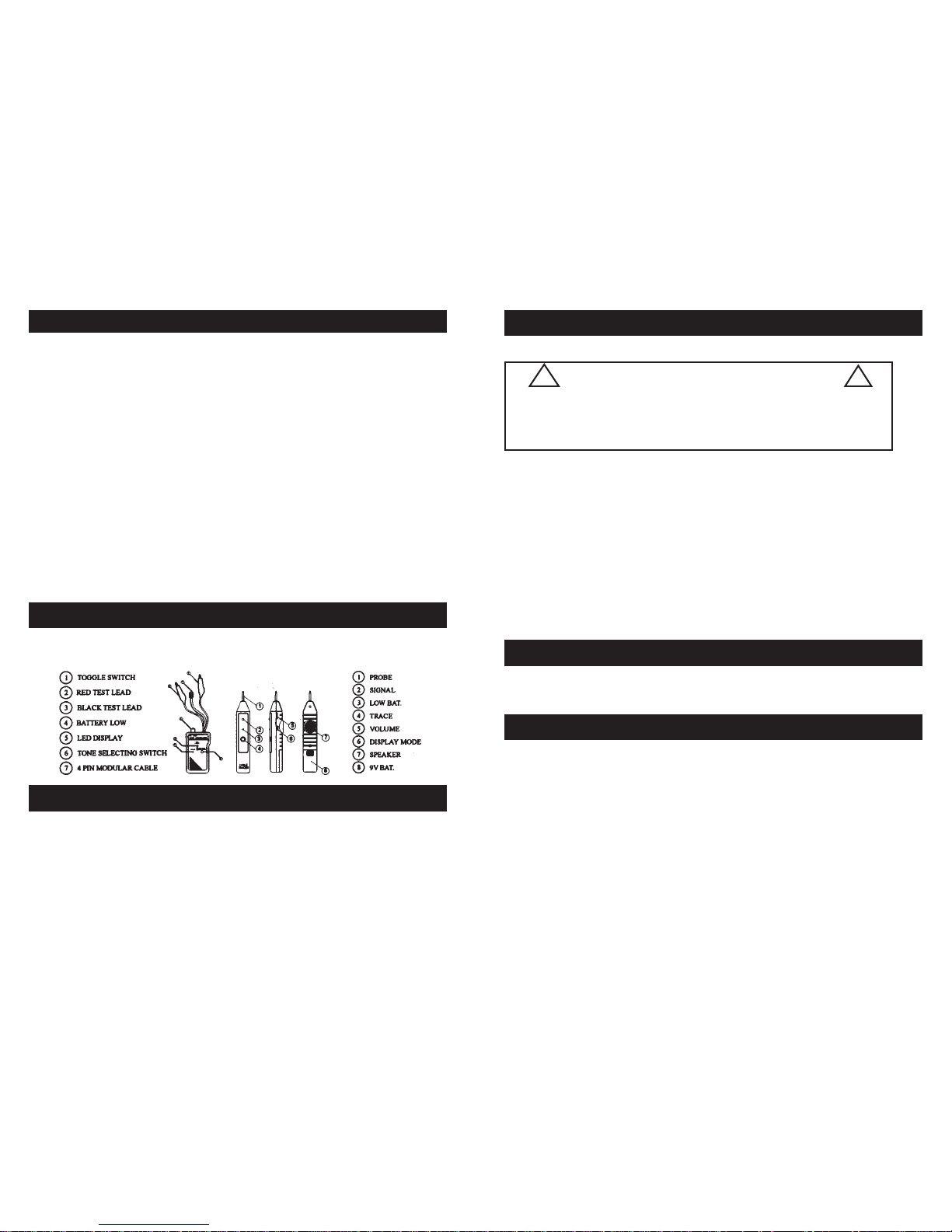
Product Profile
Tone Generator
Features:
• 2-Position switch for single tone or multi-tone signal
• Toggle switch to control 3 modes of operation
• 3-color LED indicator display for telephone line.
E.Testing Continuity
1. Slide the toggle switch to the “CONT” position
2. Connect the test leads to the subject pair
3. A BRIGHT GREEN light indicates continuity
CAUTION
Do not connect to an active AC or DC circuit
in this mode.
Failure tto ffollow tthis ccaution ccould
cause ddamage tto tthe uunit.
!!
!!
Operation (CON’T)
F. Testing Continuity Using Tone
1. Slide the toggle switch to the “TONE”position
2. Connect the test leads to the subject pair
3. Using a handset or headset at the remote end, touch the
wire end(s) with the clip lead(s)
4. Reception of tone is an indication of continuity
• All above tests are applicable to modular plugs for line 1 only (red &
green wires)
Modular T esting
• To send a tone on un-terminated coaxial cables, connect the RED test
lead to the outer shield and the BLACK test lead to the center conductor, or connect the RED test lead to the outer shield and the BLACK test
lead to ground
• To send a tone on terminated coaxial cables, connect the RED test lead
to the connector housing and the BLACK test lead to the center pin, or
connect the RED test lead to the connector housing and the BLACK test
lead to ground
Coax T esting
The TPG-70 includes the TG-50 Tone Generator and TP20 Probe in the kit.
Page 3

5 2
Tone Generator (CON’T)
polarity, continuity and voltage testing
• Black and red testing leads and standard 4-pin modular
cable for individual wire tests or modular jack tests
• Convenient compact size and simple application
Specifications:
• 1 ft. each of red and black test lead
• 1 ft. 4-pin modular cord and plug
• One 3-position toggle switch for operation mode control
• One 3-color LED display for line polarity, continuity and
voltage test
• One 2-position slide switch for tone v olume level selection
• Power: 9V DC battery
Probe
Features:
• Special inductive plastic tip which prevents accidental
shorts (possible with copper-tip tracers) when using near
high voltage devices
• Traces and identifies wires or cables in a bundle or group
without damaging cablue insulation
• Adjustable volume level for various work environments
• Both amplifier and LED for loud or dark work environments
• Can work with any existing tone generator in the market
• Power switch to prevent battery drain
Specifications:
• Pen-style casing
• Special inductive plastic tip
• One push-button TRACE switch
• One battery low LED indicator
Operation (CON’T)
D. Sending a Tone
1. Slide the toggle switch to the “TONE” position
2. Connect the test leads to a pair of wires or
attach one lead to the ground and the other
lead to either side of the line. (See Fig. 3)
3.
4. Select either a dual alternating tone or a single solid tone by positioning the button on the
face of the Tone Generator unit to “DUAL
TONE” or “SINGLE TONE”
5. Select one of the display functions (LED
only/speaker only/LED & speaker together)
by positioning the switch on the side of the
Probe to “L”, “S”, or “L & S” respectively
6. Use the Probe to trace the subject wire
7. Reception of tone will be loudest (amplifier)
or brightest (LED) on the subject wire
CAUTION
Do nnot cconnect tto aan aactive AAC circuit eexceeding 224
volts iin tthis mmode. Failure tto ffollow tthis ccaution ccould
cause ddamage tto tthe uunit.
!!
!!
Page 4

43
Probe (CON’T)
• One amplifier and one LED for signal detection
• One rotary volume level control
Operation
A. Identifying the polarity of a telephone line
1. Load the 9V battery
2. Slide the toggle switch to the “Off”
position
3. Connect the black test lead to ground
4. Connect the red test lead to the line
you wish to test
5. LED indicator results:
a. GREEN light: indicates normal polarity
b. RED light: indicates reversed polarity
c. YELLOW light: indicates presence of AC power
on the telephone line
Note: If a ground is not available, you may try to switch
the test leads around to different wires within the
pair. The LED indicator will light GREEN when the
red test lead is connected to the ringside of the line
and the black lead is connected to the ground.
B. Indicating telephone Line Condition
Operation (CON’T)
1. Load the 9V battery
2. Slide the toggle switch to the “Off” position
3. Plug the standard 4-pin modular cable into
modular wall jack
4. LED indicator results:
a. BRIGHT GREEN light: indicates a clear line
b.DIM GREEN light: indicates a busy line
c. BRIGHT FLASHING RED and GREEN light:
indicates a ringing line
Note: A DIMLY FLASHING GREEN light will result under
ringing line conditions if the line’s polarity is
reversed. If the test is begun prior to an incoming
call, the call will be blocked.
C.Verifying telephone Lines
1. Slide the toggle switch to the “CONT” position
2. Dial the number of the line you wish to verify
3.While the line is ringing, connect the red lead to
the ring side of the line, and connect the black
lead to ground.
4. Slide the toggle switch to the “Off” position. The
LED indicator will flicker RED and GREEN when
the test leads are connected to the subject pair
5.To verify identification, monitor the line and
switch the test set to “CONT”. This will terminate the call on the subject line
 Loading...