

Page 1

Page 2

Table of Contents
Warnings 1
Parts List 2
How to use it 3
Basic Troubleshooting 4
Advanced Troubleshooting 4
Project Listings 5
Projects 1 - 21 6 - 26
Batteries:
!
• Use only 1.5V AA type, alkaline batteries (not included).
• Insert batteries with correct polarity.
• Do not mix old and new batteries.
• Remove batteries when they are used up.
• Do not mix alkaline, standard (carbon-zinc), or
rechargeable (nickel-cadmium) batteries.
WARNING:
Always check your wiring before turning on a circuit. Never leave a circuit
unattended while the batteries are installed. Never connect additional batteries or any other power sources to
your circuits. Discard any cracked or
broken parts.
Adult Supervision:
Because children’s abilities vary so
much, even with age groups, adults
should exercise discretion as to which
experiments are suitable and safe (the
instructions should enable supervising
adults to establish the experiment’s
suitability for the child). Make sure your
child understands and follows all of the
safety warnings, and keeps them at
hand for reference.
Never modify your parts, as doing so
may disable important safety features
in them, and could put your child at risk
of injury.
• Do not connect batteries or battery holders in parallel.
• Do not short circuit the battery terminals.
• Never throw batteries in a fire or attempt to open its
outer casing.
• Batteries are harmful if swallowed, so keep away from
small children.
-1-
Conforms to all applicable US
government requirements.
WARNING: SHOCK HAZARD
Never connect Snap Circuits®to the electrical
outlets in your home in any way!
WARNING: MOVING PARTS
Do not touch the light motor (M7)
during operation.
!
Page 3
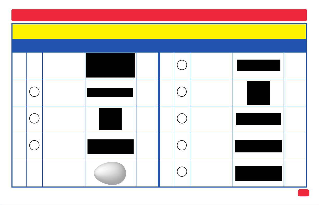
Parts List (Colors and styles may vary) Symbols and Numbers
Important: If any parts are missing or damaged, DO NOT RETURN TO RETAILER. Call customer service toll-free at
(800) 533-2441 or e-mail us at: help@elenco.com.
Qty.
r 1
r 4
r 1
r 1
r 1
ID
Name
Mini Base Grid
3
B3B
D10
Battery Holder -
uses 3 1.5V type
AA (not included)
Red/Yellow LED
(7.7” x 5.5”)
3-Snap Wire
Egg
Symbol
Part #
6SCBGM
6SC03
6SCB3B
6SCD10
6SCEGG
Qty.
r 1
r 1
r 1
r 1
r 1
ID
L4
M7
S1
S2
W1
Name
Lamp
Light Motor
Slide Switch
Press Switch
Horn
Symbol
Part #
6SCL4
6SCM7
6SCS1
6SCS2
6SCW1
-2-
Page 4

How To Use It
For each project, follow the drawings to place all STEP 1 parts on the
mini base grid, then place all STEP 2 parts, then place any additional
parts indicated by STEPS 3 or 4.
Step 1
Step 2
+
Activate the circuit using the slide switch (S1) or press switch (S2) as indicated in the final step.
Be sure that the light motor (M7), red/yellow LED (D10, and horn (W1)
have their “+” marking positioned as per the drawing.
Do not touch the light motor (M7) during
operation.
Note: While building the
projects, be careful not to
accidentally make a direct
connection across the battery holder (a “short circuit”), as this may damage
and/or quickly drain the
batteries.
-3-
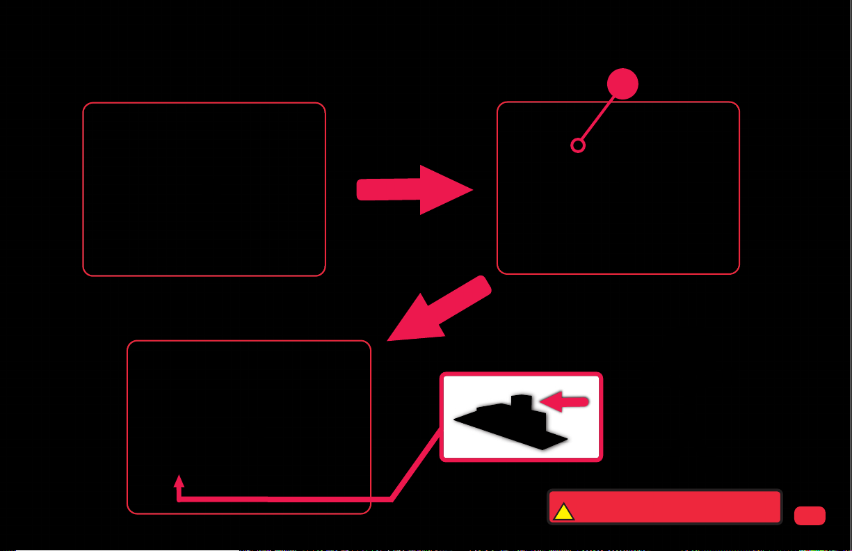
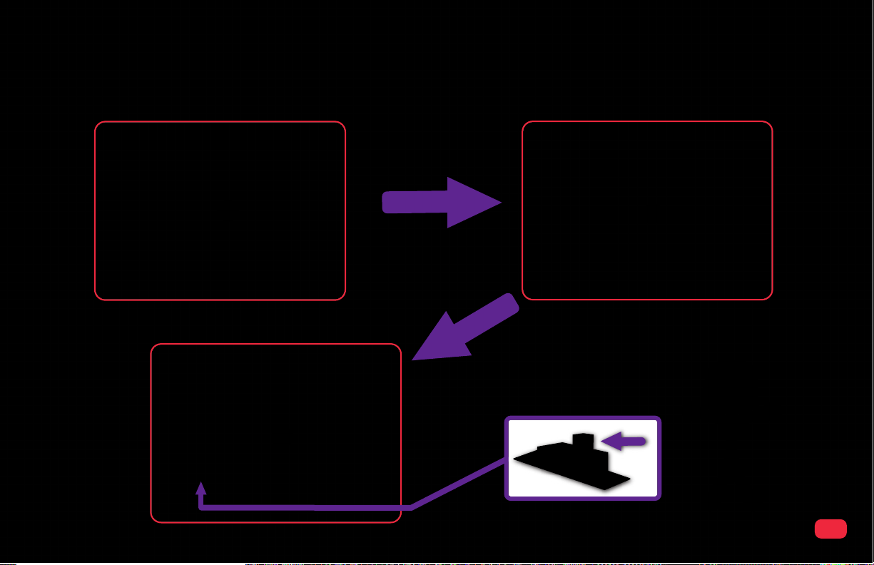
How to add or replace batteries
Remove the safety cover from the battery holder (B3B) with a Phillips head screwdriver.
Insert three (3) 1.5V “AA” batteries (not included) into the battery holder (B3B). Be sure
to orient the battery “+” side as marked in the holder.
Examples of SHORT CIRCUITS - NEVER DO THESE!!!
Placing a 3-snap wire directly
across the batteries is a
SHORT CIRCUIT.
!
NEVER
DO!
When the slide switch (S1) is turned
on, this circuit has a SHORT CIRCUIT path (as shown by the arrows). The short circuit prevents
any other portions of the circuit from
ever working.
Replace battery holder cover.
!
NEVER
DO!
Page 5

Troubleshooting
Basic Troubleshooting:
1. Most circuit problems are due to incorrect assembly, always double-check that your circuit exactly matches the drawing for it.
2. Be sure that the light motor (M7), red/yellow LED (D10, and horn (W1) have their “+” marking positioned as per the drawing.
3. Be sure that all connections are securely snapped.
4. Try replacing the batteries.
Advanced Troubleshooting (Adult supervision recommended):
If you suspect you have damaged parts, you can follow this procedure to systematically determine which ones need
replacing:
1. Lamp (L4), red/yellow LED (D10), horn (W1), light motor (M7), and battery holder (B7):
A. Place batteries in holder.
B. Place the lamp directly across the battery holder, it should light. C. Do the same with the LED, it should light red or yellow,
depending on how you oriented it.
D. Do the same with the horn (horn + to battery +), it should make an annoying sound.
E. Do the same with the light motor (motor + to battery +), it should spin to the right and its lights should be on.
F. If nothing works, then replace your batteries and repeat, if still bad then the battery holder is damaged.
3-snap wires: Build the Lamp circuit (on page 8), but replace the slide switch (S1) with a 3-snap wire; if the lamp (L4) does
2.
not light then one of the two 3-snap wires in the circuit is broken. Systematically test all four 3-snap wires in your set.
Slide switch (S1) and press switch (S2): Build the Lamp circuit (on page 8); if the
3.
lamp (L4) does not light then the slide switch is broken. Replace the slide switch with
the press switch and test it in the same way.
Customer Service
Call toll-free: (800) 533-2441
e-mail: help@elenco.com
-4-
Page 6

Project Listings
Project # Description Page # Project # Description Page #
1 Light Motor 6
2 Fan 7
3 Lamp 8
4 Red Light 9
5 Yellow Light 10
6 Horn 11
7 Light & Sound 12
8 Light & Sound with Egg 13
9 2-Speed Fan 14
10 2-Switch Everything 15
11 Dim Lights 16
12 Super Dim Lights 17
13 2-Switch Light 18
14 Either Switch Lamp 19
15 Press Light Control 20
16 Sound or Motion 21
17 2-Color Light & Sound 22
18 Fun with Sound & Lights 23
19 Fun with Switches 24
20 Lots of Lights 25
21 Egg Horn 26
-5-
Page 7
Project 1 : Light Motor
Step 1
Step 3
Step 2
+
WARNING: MOVING PARTS
Do not touch the light motor (M7) during operation.
!
-6-
Page 8

Project 2 : Fan
-7-
Step 1
Step 3
+
Step 2
WARNING: MOVING PARTS
Do not touch the light motor (M7) during operation.
!
Page 9
Project 3 : Lamp
Step 1
Step 2
Step 3
-8-
Page 10

Project 4 : Red Light
Step 1
Step 3
Optional
Step 2
RED
-9-
Page 11

Project 5 : Yellow Light
YELLOW
Step 1
Optional
Step 2
Step 3
-10-
Page 12

Project 6 : Horn
Step 1
Step 3
+
Step 2
-11-
Page 13

Project 7 : Light & Sound
Step 1
Step 3
RED or
YELLOW
WARNING: MOVING PARTS
Do not touch the light motor (M7) during operation.
!
Step 2
+
Step 4
-12-
Page 14

Project 8 : Lights & Sound with Egg
-13-
Step 1
Step 3
WARNING: MOVING PARTS
Do not touch the light motor (M7) during operation.
!
+
RED or
YELLOW
Step 4
Step 2
+
Page 15

Project 9 : 2-Speed Fan
WARNING: MOVING PARTS
Do not touch the light motor (M7) during operation.
!
Step 1
Step 3
Step 2
+
-14-
Page 16

Project 10 : 2-Switch Everything
WARNING: MOVING PARTS
Do not touch the light motor (M7) during operation.
!
+
Step 1
Step 3
+
RED or
YELLOW
Step 2
Step 4
Optional
-15-
Page 17

Project 11 : Dim Lights
WARNING: MOVING PARTS
Do not touch the light motor (M7) during operation.
!
Step 1
Step 2
+
Step 3
-16-
Page 18

Project 12 : Super Dim Lights
WARNING: MOVING PARTS
Do not touch the light motor (M7) during operation.
!
Step 1
Step 3
RED or
YELLOW
Step 2
+
Step 4
-17-
Page 19

Project 13 : 2-Switch Light
RED or
YELLOW
Step 1
Step 2
Step 3
-18-
Page 20

Project 14 : Either Switch Lamp
Step 1
Step 2
Step 3
-19-
Page 21

Project 15 : Press Light Control
RED or
Step 1
YELLOW
Step 2
Step 3
Step 4
-20-
Page 22

Project 16 : Sound or Motion
Step 1
Step 3
Step 2
+
+
-21-
WARNING: MOVING PARTS
Do not touch the light motor (M7) during operation.
!
Page 23

Project 17 : 2-Color Light & Sound
WARNING: MOVING PARTS
Do not touch the light motor (M7) during operation.
!
Step 1
Step 3
+
RED or
YELLOW
Step 2
+
Step 4
-22-
Page 24

Project 18 : Fun with Sound & Lights
-23-
Step 1
Step 3
+
Step 2
Step 4
+
WARNING: MOVING PARTS
Do not touch the light motor (M7) during operation.
!
Page 25

Project 19 : Fun with Switches
WARNING: MOVING PARTS
Do not touch the light motor (M7) during operation.
!
Step 1
Step 3
RED or
YELLOW
Step 2
+
Step 4
-24-
Page 26

Project 20 : Lots of Lights
WARNING: MOVING PARTS
Do not touch the light motor (M7) during operation.
!
Step 1
Step 3
RED or
YELLOW
Step 2
+
Step 4
-25-
Page 27

Project 21 : Egg Horn
Step 1
Step 3
+
Step 2
RED or
YELLOW
-26-
Page 28

 Loading...