

Page 1
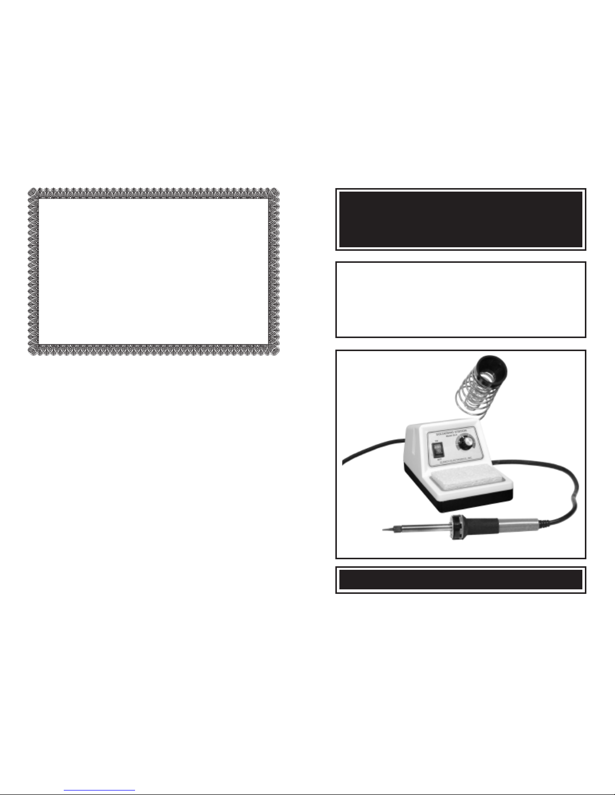
Deluxe Electronic
Soldering Station
MODEL SL-5
MODEL SL-5-40
MODEL SL-5-SPL
Instruction Manual
Elenco Electronics, Inc.
Copyright © 2002 Elenco Electronics, Inc. 753099
Elenco Electronics, Inc.
150 W. Carpenter Avenue
Wheeling, IL 60090
(847) 541-3800
http://www.elenco.com
e-mail: elenco@elenco.com
TWO YEAR WARRANTY
All Elenco models are guaranteed for two full years on all parts and
service. For the first three months, your soldering station is covered at
absolutely no charge. For the remaining 21 months, a nominal service
charge is required to cover shipping and handling. Soldering iron tip
not included in warranty.
When returning merchandise for repair, please include proof of
purchase, a brief letter of explanation of problem, and sufficient
packing material. Before returning any merchandise please call our
service department at (847) 541-3800 to obtain a return merchandise
authorization number (RMA).
Service Department
Page 2
-1- -10-
INTRODUCTION
The SL-5 series of soldering stations are quality products designed to
give the professional, student and hobbyist greater control in quality
soldering a broad range of soldering situations. The stations are
available with 40 watt soldering irons. The AC receptacle on the back
of the station allows soldering irons of up to 300 watts. The AC
receptacle also allows irons to be easily changed or replaced.
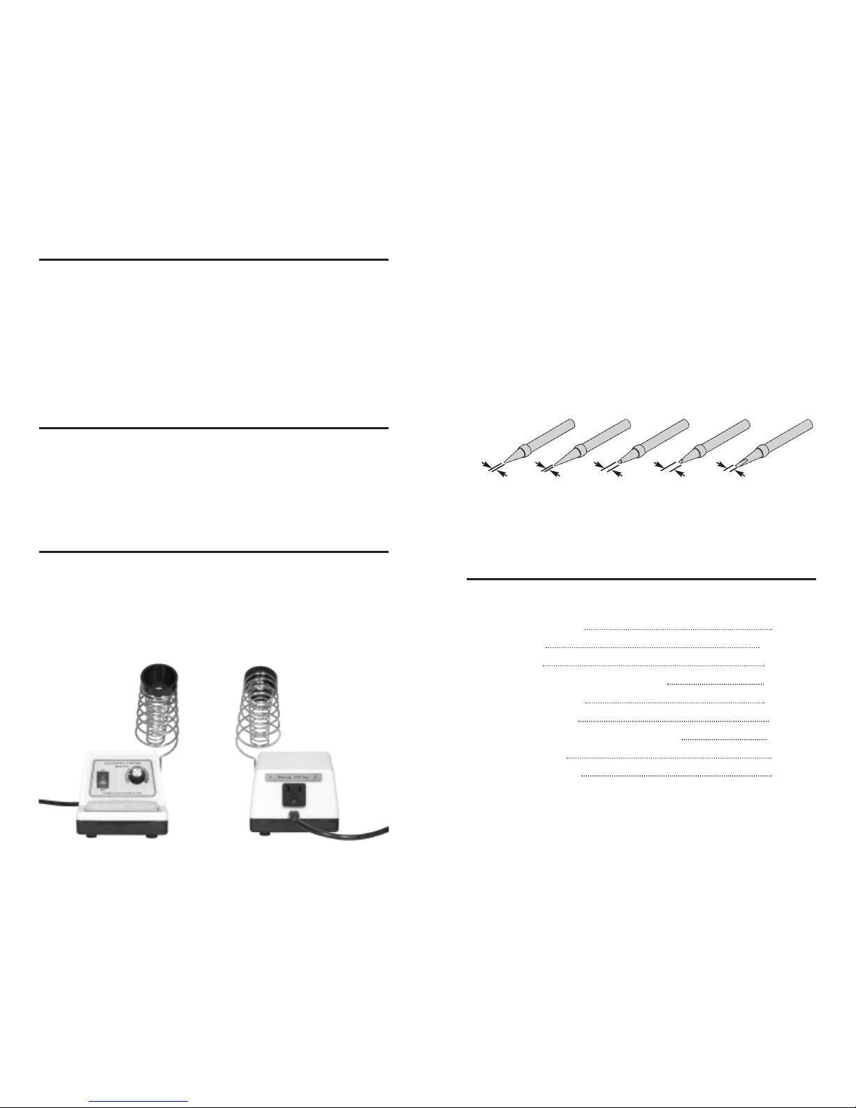
FEATURES
• Heavy Steel, Non-Slip Base
• Iron Holder Funnel - Reversible, left or right side
• Stainless Steel Tray for Sponge Pad
• Sponge Pad
• Power On/Off with Indicator Light
SOLDER STATION MODELS
The following instructions are for the following electronic soldering
stations. The model number of the electronic soldering station that you
have received, is marked on the end of the carton.
Model SL-5 is supplied without an iron.
Model SL-5-40 is supplied with a 40 watt soldering iron,
grounded plug, Model SR-6.
Model SL-5-SPL is custom packaged with an iron of your choice
and other soldering aids.
Replacements and Optional Solder Aids for SL-5
Series Solder Station
40W Soldering Iron SR-6
Conical Tip SR-2T2
Wedge Tip SR-2T
Tip Kit used with SR-6 Soldering Iron TIPK-1
Tip Tinner/ Cleaner TTC-1
Desoldering Wick SW-3
Solder 63/37 Rosin Core .032 dia. 10ft. ST-4A
Solder Ease Kit SE-1
Desoldering Pump SP-2
Tip Sizes
The tip sizes and shapes greatly effects the heating and heatrecovery.Today, tips are manufactured in a variety of different shapes.
Having a choice of tip styles allows you to choose the one best suited
for your soldering needs.
Shown below is a soldering iron tip package of 5 tip sizes (Model
TIPK-1) that can be used with Elenco’s soldering irons SR-2B and
SR-6. Due to high heat, removable tips can bond themselves to the
heating element if left in place for extended periods. Periodic removal
of the tip is therefore advisable.
1/32”
1/64” 1/16” 1/8” 3/64”
Tip Package Model TIPK-1
Page 3

Types of Poor Soldering Connections
1. Insufficient Heat - the solder
will not flow onto the lead
as shown.
2. Insufficient Solder - let the
solder flow over the connection
until it is covered. Use just enough
solder to cover the connection.
3. Excessive Solder - could make
connections that you did not intend
to between adjacent foil areas or
terminals.
-2--9-
OPERATION
• Carefully remove the SL-5 parts from the box.
• Insert the iron holder on either the right or the left side.
• Wet the sponge with preferably distilled or tap water, and then place
it into the tray.
• Set the On/Off switch to the Off position and the control knob at
minimum.
• Plug the soldering iron line cord into the AC receptacle on the back
of the station and place the soldering iron into the iron holder
funnel.
• Plug the line cord of the solder station into a 120-volt, 60Hz AC
receptacle.
• Turn the power switch On and set the temperature control to
maximum.
• We will now tin the tip by applying solder to the tip as it heats up
.
DO
IT before the tip becomes too hot.
• Set the temperature setting to the temperature desired for
soldering. If you are not going to use the iron immediately, set the
temperature in the park
position.
General Areas of Temperature Settings for 40W Iron
4. Solder Bridges - A solder
bridge occurs when solder
runs between circuit paths and
creates a short circuit. This is
usually caused by using too
much solder. To correct this,
simply drag your soldering iron
across the solder bridge as
shown.
Rosin
Soldering iron positioned
incorrectly.
Solder
Gap
Component Lead
Solder
Soldering Iron
Drag
Foil
Use these settings for
soldering temperature
sensitive components.
Use these settings for
general soldering and
connections that
require more heat.
Park Position
In these settings,
temperatures are too
low for soldering. Set
the station in these
positions when not
using it to reduce
oxidation of the
soldering iron tip.
300
550
750
670
Page 4

-3- -8-
SAFETY PRECAUTIONS
Like all electrical devices, the solder station must be handled with
care. The soldering iron and tip can reach high temperatures and
these simple safety rules should be followed.
1. Keep children out of reach of the soldering station.
2. To protect your eyes, use safety goggles.
3. Keep flammable material away from the soldering iron.
4. DO NO
T cool iron by dipping it into any liquid or water.
5. Always assume that the tip is hot to avoid burns.
6. Work in an area that is well ventilated.
7. Be careful that the hot soldering iron tip or the barrel of the iron
does not come in contact with any electrical cord.
8. Do not hold solder in your mouth. Solder contains lead and is
a toxic substance. Wash your hands thoroughly after handling
solder.
9. Locate solder station in an area where you do not have to go
around it or reach over it.
Soldering Surface Mount Components
Using tweezers or small long nose pliers, place the iron in contact
with the PC board foil. Apply a small amount of solder simultaneously
to the foil and components, allowing them to melt the solder.
Remove the iron and allow the solder to cool. The solder should have
flowed freely and not lumped around the component.
Apply the lowest heat possible while still having solder flow freely
(suggested temperature setting: 625
O
F).
Heat Sinking
Electronic components such as transistors, IC’s, and diodes can be
damaged by the heat during soldering. Heat sinking is a way of
reducing the heat on the components while soldering. Dissipating the
heat can be achieved by using long nose pliers, an alligator clip, or a
special heat dissipating clip. The heat sink should be held on the
component lead between the part and the solder joint.
Heat Sink
(this can be ordered as part of
Elenco’s Solder Ease Kit Model
SE-1 - see Page 10).
Soldering Iron
Solder
Heat Sensitive
Component (Diode)
PC Board
Tweezers or Pliers
Solder
Soldering Iron
Surface Mount Component
Page 5

-4--7-
Solder
Soldering Iron
Foil
3. Allow the solder to flow around the
connection. Then, remove the solder
and the iron and let the connection cool.
The solder should have flowed smoothly
and not lump around the wire lead.
4. Here is what a good solder connection
looks like.
Solder
Soldering Iron
Foil
2. Apply a small amount of solder to the
iron tip. This allows the heat to leave the
iron and onto the foil. Immediately apply
solder to the opposite side of the
connection, away from the iron. Allow
the heated component and the circuit foil
to melt the solder.
SOLDERING
A poorly soldered joint can greatly effect small current flow in circuits
and can cause equipment failure. You can damage a PC board or a
component with too much heat or cause a cold solder joint with
insufficient heat. Sloppy soldering can cause bridges between two
adjacent foils preventing the circuit from functioning.
What Good Soldering Looks Like
A good solder connection should be bright, shiny, smooth, and
uniformly flowed over all surfaces.
Soldering a PC board
1. Solder all components from the copper
foil side only. Push the soldering iron tip
against both the lead and the circuit
board foil.
Component Lead
Soldering Iron
Circuit Board
Foil
SOLDERING IRONS
Iron wattage varies from 15 to over 100 watts. For working on PC
boards, irons ranging from 15 to 40 watts is suitable. If a heavy-duty
soldering iron is required, a 60 watt iron should be considered. If you
use an iron with a higher wattage rating than 40 watts, you may
damage the copper tracks on the PC board. The higher wattage irons
are best suited for heavy-duty electrical connections.
Soldering Iron Tip
The tip is the very important part of the iron. The material that the tip
is made from is an important factor. The soldering iron tip contains
four different metals see figure below. The core consists of copper.
Since the copper is a soft material, it is plated with iron. Then the tip
is plated with tin, because it can be easily cleaned. Chrome plating
is used on the area where no soldering takes place to prevent
oxidation.
CopperIron Plating Chrome PlatingTin Plating
Tip Cleaning
A good clean solder tip makes soldering much easier. The tip should
be tinned by lightly coating it with solder to prevent it from oxidizing.
The tip can become pitted (black spots) from normal use. It is
important to clean the tip by wiping it with a wet sponge or rag. For
tips that need a good cleaning, the tip tinnier and cleaner (#TTC1)
should be used. Ne
ver use a file or abrasive material to clean the
tip. Using such methods will damage the plating and ruin the tip. Do
not remove the excess solder from the tip before storing. The excess
solder will prevent oxidation.
Page 6

-5- -6-
Surface Preparation
In order for the solder to adhere to the connection, the metals must
be clean and free of non-metallic materials. Flux in the solder can
remove oxides from metal but not other materials like dirt or grease.
To remove these, use a small steel brush or fine emery cloth.
Mechanical Connection
When all the surfaces are clean, the metals should have a solid
mechanical connection. Wires should be tightly wrapped around
each other or to the terminal. This will eliminate large gaps that create
weak solder joints. Solder should not be used as a mechanical
connection.
Solder
Rosin Core
Solder
Solder is a fusible alloy composed of tin and lead. Some solder may
contain small amounts of other material for use in special purposes
to enhance its characteristics. Solder has a melting temperature
around 361
O
to 370O, making it ideal for forming a metallic joint
between two metals.
Solder is identified by the ratio of tin-to-lead. The most common
ratios are 63/37 and 60/40. Solder with a greater tin content melts at
a lower temperature, takes less time to harden, and generally makes
it easier to do a good soldering job. The ratio of tin is a main factor in
the strength of the solder joint. Solder with a greater tin content has
a greater holding ability under stress. Rosin core solders (.031”
diameter) are ideal for use in soldering electronic circuits.
SolderWire Terminal
INTRODUCTION TO SOLDERING
Almost every electronic device today has a printed circuit (PC) board.
Whether you are assembling a PC board or repairing it, you must
understand the basics of working with these boards.
A poorly soldered joint can greatly effect small current flow in circuits
and can cause equipment failure. You can damage a PC board or a
component with too much heat or cause a cold solder joint with
insufficient heat. Sloppy soldering can cause bridges between two
adjacent foils preventing the circuit from functioning.
Good soldering requires practice and an understanding of soldering
principles. Solder (a tin-lead fusible alloy) is use to form a metallic
union or joint between two metals.
For best results, the soldering iron should be at least 100
O
F above the
melting point of solder (361OF). Generally, a minimum temperature of
650OF is desirable for printed circuit boards, while higher
temperatures are needed for proper soldering to heavier terminals.
Listed below are some basic steps that should be followed to make
good solder joints.
1. Make sure that the part that is to be soldered is clean.
2. Where possible, make good mechanical connections.
3. Use quality 63/37 or 60/40 rosin core solder. NEVER USE ACID
CORE SOLDER OR FLUX.
4. Apply heat to the base material or wires so that they become hot
enough to melt the solder.
5. Slide the soldering iron away from the joint to leave a neat joint.
6. After removing iron, do not move joint.
7. On temperature sensitive components such as transistors,
diodes, and IC’s, avoid too much heat. Use a heat sink to
dissipate heat away from the component.
 Loading...