

Page 1
If you have any problems, contact Elenco
®
Copyright © 2014 Elenco®Electronics, Inc. All Rights Reserved. ● 150 Carpenter Ave. ● Wheeling, IL 60090
(800) 533-2441 Fax: (847) 520-0085 ● e-mail: elenco@elenco.com ● Website: www.elenco.com or www.snapcircuits.net
W
ARNING: SHOCK HAZARD -
Never connect Snap Circuits
®
to the electrical outlets in your
h
ome in any way!
WARNING: Always check yo ur wiring before
t
urning on a ci rcuit. Nev er leave a circuit
unatten ded whil e the batteries are installed.
N
ever connect additional batteries or any other
power sources to your circuits.
Motion Detector
Model SCP-13
753162
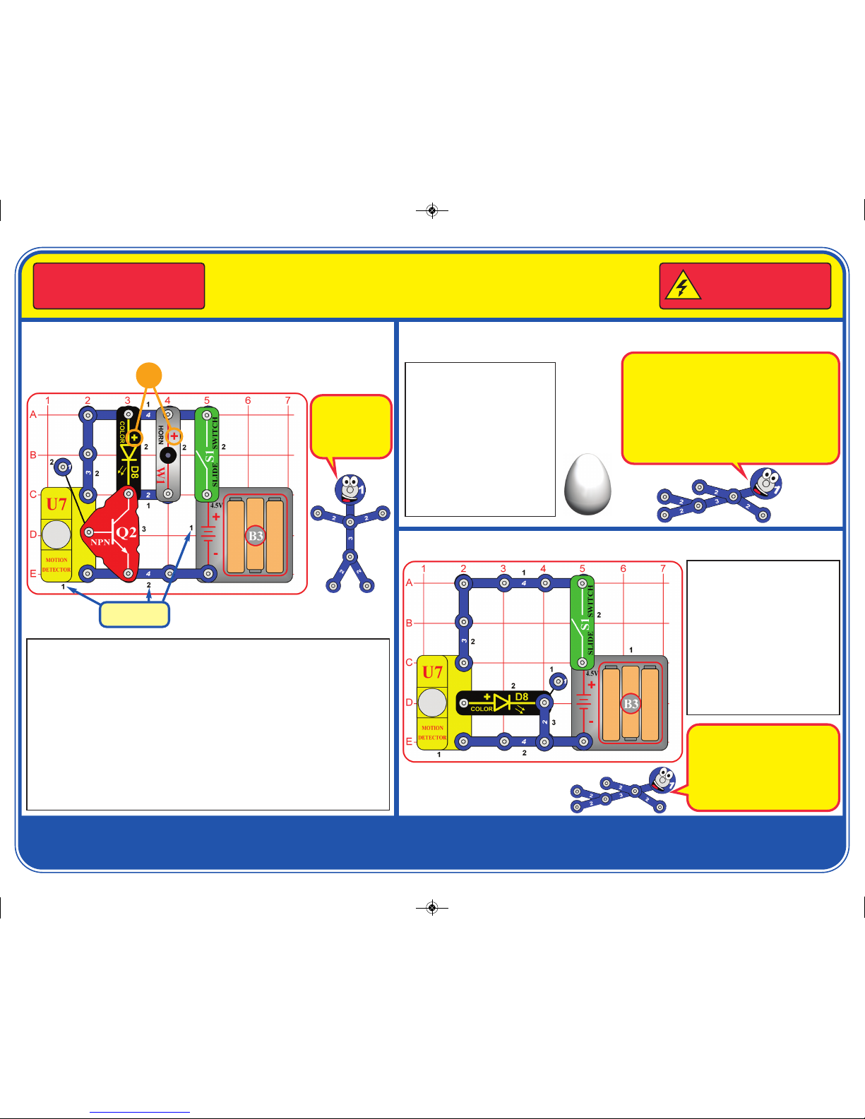
Snap Circuits®uses electronic blocks that snap onto a base grid to build different
circuits. These blocks have different colors and numbers on them so that you can
easily identify them. Build the circuit shown by placing all the parts with a black 1
next to them on the clear base grid first. Then, assemble parts marked with a 2.
Then, assemble the part marked with a 3. Install three (3) “AA” batteries (not
included) into the battery holder (B3). Place the base grid into the blue stand (with
either the battery holder or the NPN transistor (Q2) closest to the stand) and
carefully stand it up. Position it near the edge of a table, facing across a room.
Turn on the slide switch (S1). The color LED (D8) lights and the horn (W1) sounds
for a few seconds on start-up, and then whenever the circuit detects motion in the
room.
This circuit will work in the dark, but be careful not to hurt yourself moving around
a room in the dark.
Project 1 Motion Detector
Placement
Level Numbers
+
Project 2 Silent or Noisy Motion Detector
Use the circuit from project 1,
but remove the horn (W1). The
circuit works the same, except
no longer makes any noise. If
desired, try placing the egg on
the color LED (D8), but it may
not fit tightly enough to stay on
when the circuit is placed in the
blue stand.
Next, replace the color LED
(D8) with the horn. Now the
circuit makes noise but not light.
Egg
(place on
color LED)
Project 3 Low Power Motion Detector
Place the base grid into the blue
stand (with either the battery
holder or the 2-snap wire
closest to the stand) and
carefully stand it up. Position it
near the edge of a table, facing
across a room.
Turn on the slide switch (S1).
The color LED (D8) lights for a
few seconds on start-up, and
then whenever the circuit
detects motion in the room.
This circuit is
pictured on the
front of the box,
use that picture to
help in building it.
Objects that generate heat, including people and
animals, also produce infrared radiation. Infrared
radiation cannot be seen wth our eyes, but can be
detected.
The motion detector (U7) is designed to detect
changes in infrared radiation, especially the type
emitted by people. The NPN transistor (Q2) acts as
an amplifier, helping the motion detector turn on the
color LED and horn.
The color LED will not be as bright
as it was in pro jects 1 & 2,
because this circuit does not have
the NPN transistor (Q2) as an
amplifier. This circuit uses less
electricity than projects 1 & 2, so
your batteries will last longer.
SCP-13_022014.qxp_SCP-13 Instructions 3/7/14 10:46 AM Page 1
Page 2
Turn on the switch (S1) to see light and
hear a buzzing sound. The buzzing is
synchonized with the changing light.
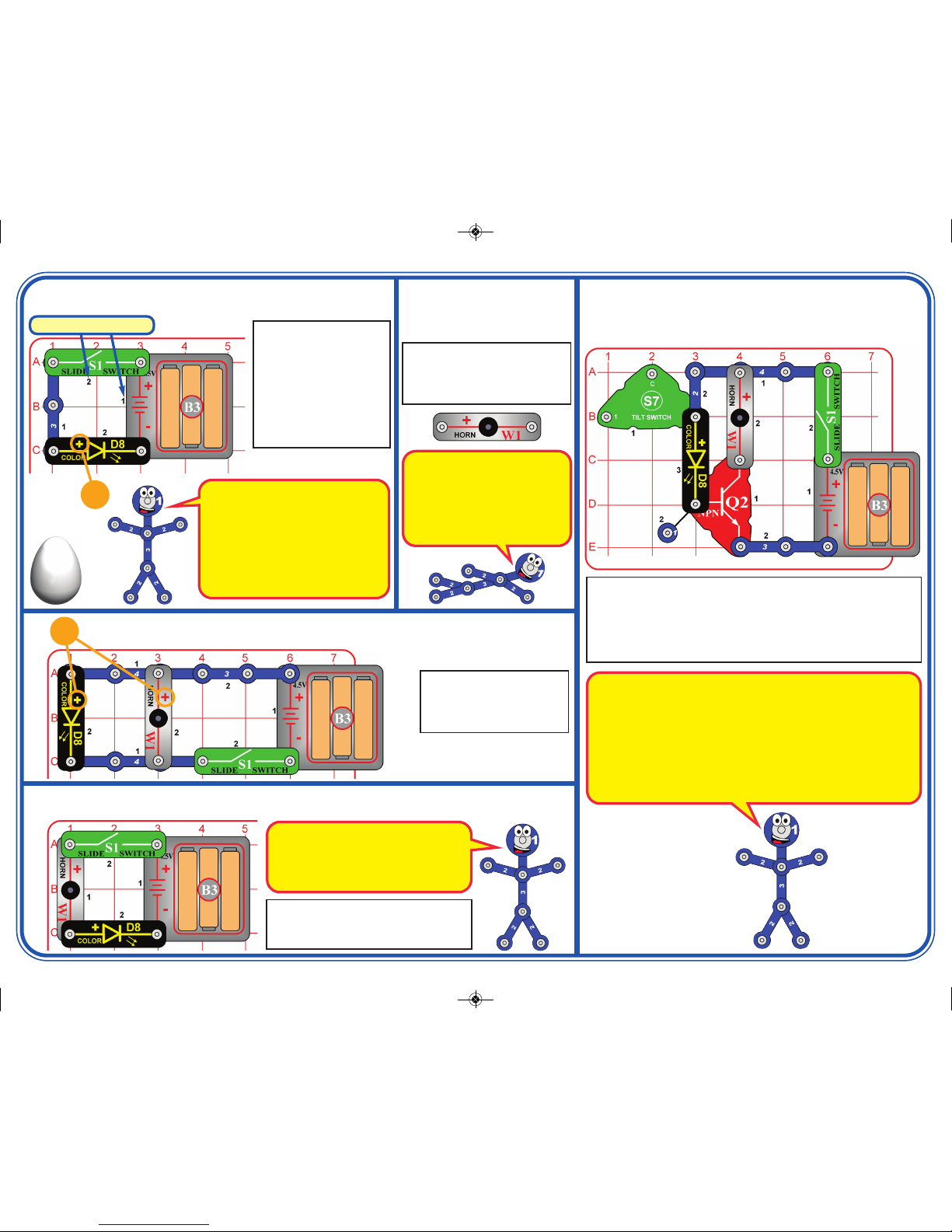
Project 7 Low Light & Sound
Project 6 Light & Sound
Turn on the switch (S1) to
see light and hear sound. If
desired, place the egg on
the color LED D8).
+
Turn on the switch (S1) to see light and hear the horn (W1). The
horn is synchonized with the changing light from the color LED (D8).
As a variant, try swapping the locations of the color LED & horn.
The tilt switch (S7) is used as a spacer here, and is not electrically
connected.
Project 8
Super Light & Sound
Project 5
Horn
Use the circuit from project 4, but
replace the color LED (D8) with
the horn (W1, “+” on left). Turn on
the switch (S1) to hear the horn.
Build the circuit as shown,
and turn on the slide
switch (S1). The color
LED (D8) is changing
colors in a repeating
pattern. If desired, place
the egg on the color LED.
For best effects, place the
circuit in a dimly lit room.
Project 4 Color Light
+
Egg
(place on
color LED)
Placement Level Numbers
The NPN transistor (Q2) can be used as an electronic switch, allowing
one circuit to control another.
When the color LED changes colors, the electric current through it also
changes. The NPN transistor uses this changing current to control the
electric current through the horn, which changes the sound it produces.
When you swap the locations of the color LED & horn, the electric
current through the horn is now controlling the electric current through
the color LED. The horn current is not changing like the LED current
was, so now both the horn and color LED just operate normally.
This circuit has the color LED and horn
connected in a series (not in parallel, as in
project 5). This arrangement makes the
LED dimmer and the sound less loud, but
makes the batteries last longer.
The color LED is a light emitting diode,
which converts electrical energy into
light; the color of the light emitted
depends on the characteristics of the
material used. The color LED actually
contains separate red, green, and blue
light emitting diodes, with a microcircuit controlling them. LEDs are more
energy efficient than normal light bulbs.
The horn converts electricity into
sound by making mechanical
vibrations. These vibrations create
variations in air pressure which
travel across the room. You “hear”
when your ears feel these air
pressure variations.
SCP-13_022014.qxp_SCP-13 Instructions 3/7/14 10:46 AM Page 2
Page 3

Project 9
Motion & Tilt Sensor
Turn on the slide switch (S1). There will be light if the circuit is moved or tilted in some
directions. In some cases the circuit may detect tilt even if laying on a flat surface; tilt
if slightly to make it turn off.
Next, remove the color LED and place it across the points marked A & B (“+” to point
A). Now the color LED activates when the circuit is tilted in different directions.
Next, replace the color LED with the horn (W1). The circuit works the same, except
makes sound instead of light.
Note that the actual tilt switch component may be mounted inside its case, and may
not be visible from the outside.
Place the circuit on a level surface
and turn on the switch (S1). There
will be light if the circuit is tilted or
moved. As a variant, try replacing the
color LED (D8) with the horn (W1);
you hear buzzing when tilt is
detected.
If the circuit does not shut off when
left alone, then try tilting it slightly so
it turns off.
Project 11 Motion & Tilt Light
Place the circuit on a level
surface and turn on the
switch (S1). There will be
light or sound if the circuit is
tlited or moved. As a variant,
try swapping the locations of
the color LED (D8) and horn
(W1).
If the circuit does not shut off
when left alone, then tilt it
slightly so it turns off.
Project 10
Super Motion & Tilt Sensor
Turn on the slide switch (S1). Place the base grid into the blue stand, oriented so that
there is no sound (usuaully this will be with the 2-snap wire or the battery holder closest
to the stand). Position it near the edge of a table, facing across a room.
The color LED (D8) lights whenever the circuit detects motion in the room. The horn (W1)
makes noise if the circuit is moved or tilted in some directions.
Project 12
Motion Detector with Touch Alarm
The tilt switch (S7) has a
rolling ball sensor mounted
inside and can detec t tilt,
vibration, or acceleration.
It is more difficult to get this circuit
to turn off than it was for project 10,
because in project 10 the color
LED and horn indicate different
directions of tilt.
This circuit could be used
as a security system. It
lights if it detects someone
moving across the room,
and sounds an ala rm if
someone tries to move the
circuit out of their path.
SCP-13_022014.qxp_SCP-13 Instructions 3/7/14 10:46 AM Page 3
Page 4

Important: If any parts are missing or
damaged, DO NOT RETURN TO
RETAILER. Call toll-free (800) 533-2441 or
e-mail us at: help@elenco.com.
Customer Service ● 150 Carpenter Ave. ●
Wheeling, IL 60090 U.S.A.
You may order additional / replacement
parts at our website: www.snapcircuits.net
Qty. ID Name Part #
r 1 1 1-snap wire 6SC01
r 1 2 2-snap wire 6SC02
r 1 3 3-snap wire 6SC03
r 2 4 4-snap wire 6SC04
r 1 B3 Battery holder 6SCB3
r 1 Base grid 6SCBGM
r 1 D8 Color LED 6SCD8
r 1 Egg 6SCEGG
r 1 Q2 NPN transistor 6SCQ2
r 1 S1 Slide switch 6SCS1
r 1 S7 Tilt switch 6SCS7
r 1 U7 Motion detector 6SCU7
r 1 W1 Horn 6SCW1
r 1 Stand 626100
OTHER SNAP CIRCUITS®PRODUCTS! PARTS LIST
Contact Elenco®to find out where you can purchase these products.
Snap Circuits®Jr. Model SC-100
Build over 100 projects, contains over 30 parts.
Flying Saucer Plus
Model SCP-09
FM Radio
Model SCP-12
Strobe Light & Sound
Model SCP-14
Basic Electricity
Model SCP-10
Snap Circuits®Light Model SCL-175
Build over 175 projects, contains over 55 parts.
Snap Circuits®Green Model SCG-125
Build over 125 projects, contains over 40 parts.
Snap Circuits®Sound Model SCS-185
Build over 185 projects, contains over 40 parts.
BATTERIES:
● Use only 1.5V AA type, alkaline
batteries (not included).
● Insert batteries with correct polarity.
● Non-rechargeable batteries should not
be recharged. Rechargeable batteries
should only be charged under adult
supervision, and should not be
recharged while in the product.
● Do not mix alkaline, standard (carbonzinc), o r rechargeable (nickelcadmium) batteries.
● Do not mix old and new batteries.
●
Remove batteries when they are used up.
● Do not short circuit the battery
terminals.
● Never throw batteries in a fire or
attempt to open its outer casing.
● Batteries are harmful if swallowed, so
keep away from small children.
LED Fun
Model SCP-11
SCP-13_022014.qxp_SCP-13 Instructions 3/7/14 10:46 AM Page 4
 Loading...