

Page 1
Copyright © 2017 by Elenco®Electronics, Inc. All rights reserved. No part of this book shall be reproduced by 753135
any means; electronic, photocopying, or otherwise without written permission from the publisher.
U.S. Patents: 7,144,255; 7,273,377, & patents pending
Projects 1 - 163
Instruction Manual
8-108
AGES
Project 40
Project 36
SC-3DMEG_Manual.qxp_SC-3Di_Manual_060816 6/19/17 7:29 PM Page 1
Page 2
-1-
1.
Most circuit problems are due to incorrect assembly, always
double-check that your circuit exactly matches the drawing for it.
2. Be sure that parts with positive/negative markings are
positioned as per the drawing.
3. Be sure that all connections are securely snapped.
4. Try replacing the batteries.
Elenco®is not responsible for parts damaged due to
incorrect wiring.
Basic Troubleshooting
Note: If you suspect you have damaged parts, you can follow the
Advanced Troubleshooting procedure on page 11 to determine which
ones need replacing.
Basic Troubleshooting 1
Parts List 2 - 3
How to Use Snap Circuits® 4 - 6
About Your Snap Circuits®Parts 7 - 8
Introduction to Electricity 9
DOs and DON’Ts of Building Circuits 10
Advanced Troubleshooting 11
Project Listings 12 - 13
Projects 1 - 163 14 - 92
Bonus Circuits 93 - 96
Going Further 97
Other Snap Circuits®Products 98
WARNING: SHOCK HAZARD - Never connect
Snap Circuits
®
to the electrical outlets in your home
in any way!
Table of Contents
WARNING: Always check your
wiring before turning on a circuit.
Never leave a circuit unattended
while the batteries are installed.
Never connect additional batteries or
any other power sources to your
circuits. Discard any cracked or
broken parts.
Adult Supervision:
Because children’s abilities vary so
much, even with age groups, adults
should exercise discretion as to
which experiments are suitable and
safe (the instructions should enable
supervising adults to establish the
experiment’s suitability for the child).
Make sure your child reads and
follows all of the relevant instructions
and safety procedures, and keeps
them at hand for reference.
This product is intended for use by
adults and children who have
attained sufficient maturity to read
and follow directions and warnings.
Never modify your parts, as doing so
may disable important safety
features in them, and could put your
child at risk of injury.
CAUTION: High intensity light. Do
not look directly at the white LED
(D6).
● Use only 1.5V AA type, alkaline
batteries (not included).
● Insert batteries with correct
polarity.
● Non-rechargeable batteries
should not be recharged.
Rechargeable batteries should
only be charged under adult
supervision, and should not be
recharged while in the product.
● Do not connect batteries or
battery holders in parallel.
● Do not mix old and new batteries.
● Do not mix alkaline, standard
(carbon-zinc), or rechargeable
(nickel-cadmium) batteries.
● Remove batteries when they are
used up.
● Do not short circuit the battery
terminals.
● Never throw batteries in a fire or
attempt to open its outer casing.
●
Batteries are harmful if swallowed,
so keep away from small children.
Batteries:
!
WARNING: CHOKING HAZARD - Small parts. Not
for children under 3 years.
!
Conforms to all applicable U.S. government requirements and
CAN ICES-3 (B)/NMB-3 (B).
SC-3DMEG_Manual.qxp_SC-3Di_Manual_060816 6/19/17 7:29 PM Page 2
Page 3
-2-
Important: If any parts are missing or damaged, DO NOT RETURN TO RETAILER. Call toll-free (800) 533-2441 or e-mail us at:
help@elenco.com. Customer Service ● 150 Carpenter Ave. ● Wheeling, IL 60090 U.S.A.
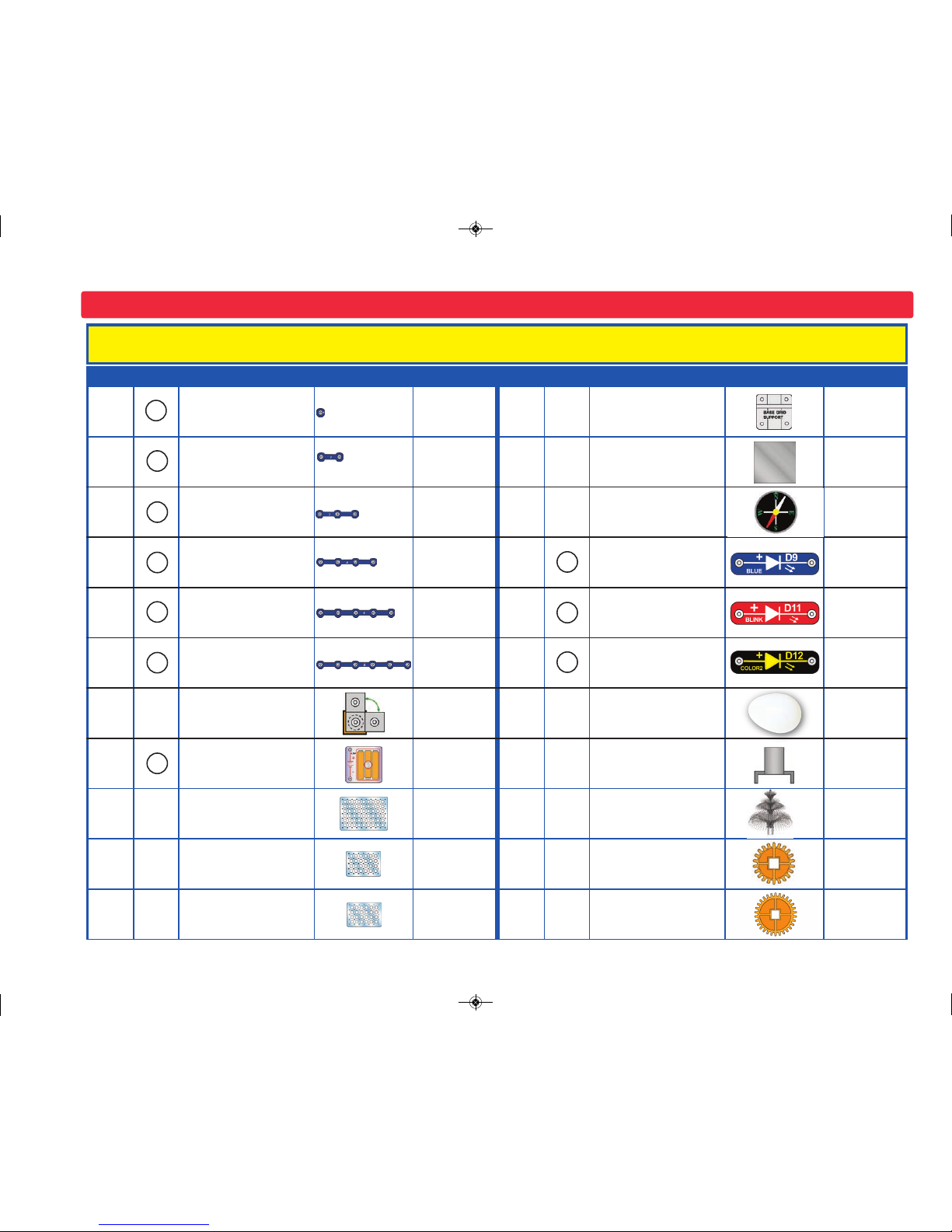
Parts List (Colors and styles may vary) Symbols and Numbers
Qty. ID Name Symbol Part # Qty. ID Name Symbol Part #
r 3
1-Snap Wire
6SC01
r 4
Base Grid Support
6SCBGSUP
r 6
2-Snap Wire
6SC02
r 1
Illusion Cards
6SCCARD1
r 3
3-Snap Wire
6SC03
r 1
Compass
6SCCOM
r 1
4-Snap Wire
6SC04
r 1
Blue LED
6SCD9
r 1
5-Snap Wire
6SC05
r 1
Blink Red LED
6SCD11
r 1
6-Snap Wire
6SC06
r 1
Color2 LED
6SCD12
r 2
3D Snap
6SC3DSNAP
r 1
EGG
6SCEGG
r 1
Battery Holder - uses
three (3) 1.5V type
“AA” (not Included)
6SCB3
r 1
Mounting Base
6SCFMB
r 1
Base Grid
(11.0” x 7.7”)
6SCBG
r 1
Fiber Optic Festive Tree
6SCFT2
r 3
Base Grid Mini
(7.7” x 5.5”)
6SCBGM
r 1
Small Gear (22T)
6SCGEAR5
r 1
Base Grid Mini 2-Side
(7.7” x 5.5”)
6SCBGM2
r 1
Large Gear (30T)
6SCGEAR6
5
4
3
2
1
B3
6
D11
D9
D12
SC-3DMEG_Manual.qxp_SC-3Di_Manual_060816 6/19/17 7:29 PM Page 3
Page 4
-3-
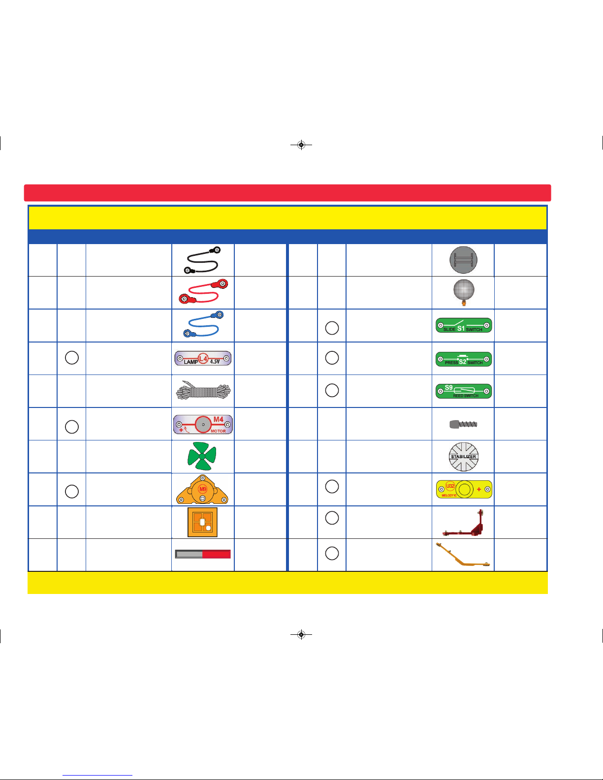
Parts List (Colors and styles may vary) Symbols and Numbers
Important: If any parts are missing or damaged, DO NOT RETURN TO RETAILER. Call toll-free (800) 533-2441 or e-mail us at:
help@elenco.com. Customer Service ● 150 Carpenter Ave. ● Wheeling, IL 60090 U.S.A.
Qty. ID Name Symbol Part # Qty. ID Name Symbol Part #
r 1
Jumper Wire (Black) 6SCJ1
r 1
Illusion Card Holder
6SCMBASE2
r 1
Jumper Wire (Red) 6SCJ2
r 1
Mirror Ball
6SCMIRBAL
r 2
Jumper Wire (Blue) 6SCJ4
r 1
Slide Switch 6SCS1
r 1
4.5V Lamp 6SCL4
r 1
Press Switch 6SCS2
r 1
String 6SCM1S
r 1
Reed Switch 6SCS9
r 1
Clear Motor 6SCM4
r 1
Screw PM 3x8 mm
6SCSCREW3
r 1
Wind Fan 6SCM4B
r 6
Stabilizer 6SCSTAB
r 1
Orange Motor 6SCM9
r 1
Melody IC 6SCU32
r 1
Gear Insert 6SCM9B
r 4
90° Vertical Snap Wire
6SCV1
r 1
Magnet 6SCMAGFF
r 2
45° Vertical Snap Wire
6SCV2
L4
V1
M9
V2
U32
S2
S1
S9
You may order additional / replacement parts at our website: www.snapcircuits.net
M4
SC-3DMEG_Manual.qxp_SC-3Di_Manual_060816 6/19/17 7:29 PM Page 4
Page 5
-4-
Snap Circuits®uses building blocks with snaps
to build the different electrical and electronic
circuits in the projects. Each block has a
function: there are switch blocks, light blocks,
battery blocks, different length wire blocks, etc.
These blocks are different colors and have
numbers on them so that you can easily
identify them. The blocks you will be using are
shown as color symbols with level numbers
next to them, allowing you to easily snap them
together to form a circuit.
For Example:
This is the slide switch, it is green and has the
marking on it. The part symbols in this
booklet may not exactly match the appearance
of the actual parts, but will clearly identify them.
This is a wire block which is blue and comes
in different wire lengths.
This one has the number , , , ,
or on it depending on the length of the wire
connection required.
There is also a 1-snap wire that is used as a
spacer or for interconnection between different
layers.
You need a power source to build each circuit.
This is labeled and requires three (3) 1.5V
“AA” batteries (not included).
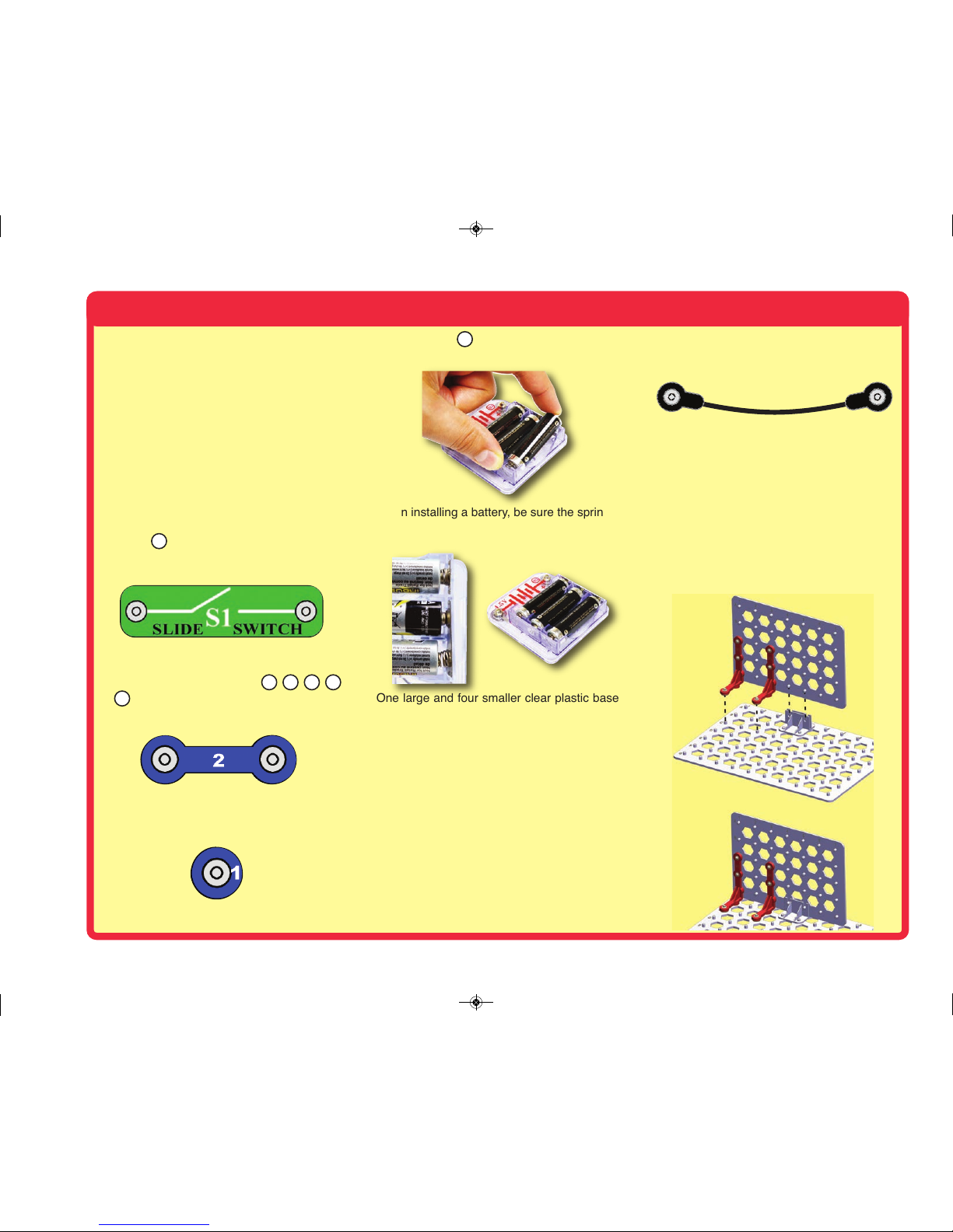
When installing a battery, be sure the spring
is compressed straight back, and not bent up,
down, or to one side.
One large and four smaller clear plastic base
grids are included with this kit to help keep the
circuit blocks properly spaced. You will see
evenly spaced posts that the different blocks
snap into. The large base has rows labeled AG and columns labeled 1-10, and the small
base has rows labeled A-E and columns
labeled 1-7. It should be obvious whether to
use a small base grid or a large base grid. For
small circuits that only need one grid, either
size may be used.
Next to each part in every circuit drawing is a
small number in black. This tells you which
level the component is placed at. Place all
parts on level 1 first, then all of the parts on
level 2, then all of the parts on level 3, etc.
Some circuits use the jumper wires to make
unusual connections. Just clip them to the
metal snaps or as indicated.
When assembling the 3D circuits, the order in
which parts are installed is important. In
particular, the vertical snap wires (V1) need to
be snapped onto the mini base grid first and
then the mini base grid is slid into the base grid
support as shown below. One of the small
grids has pegs on both sides and six thrusnaps. Some projects will indicate that this grid
must be (or must not be) used in a specific
location, otherwise it may be used
interchangeably with the other small grids.
2
3
4
6
How to Use SnapCircuits
®
B3
S1
5
SC-3DMEG_Manual.qxp_SC-3Di_Manual_060816 6/19/17 7:30 PM Page 5
Page 6
Due to the complex nature of building 3D
circuits, the circuit diagrams use special
symbols that may need additional clarification.
One such example is the symbol for the
vertical snap wire (V1). It consists of two parts,
the horizontal base and vertical stem. In the
illustration below, the base is attached to the
large base grid and the stem is attached to the
mini base grid. The symbol makes V1 appear
as two separate parts, but in reality the symbol
is connected at the red circular ends.
The 45 degree vertical snap wire (V2) is similar
to V1 but mounts at a 45 degree angle
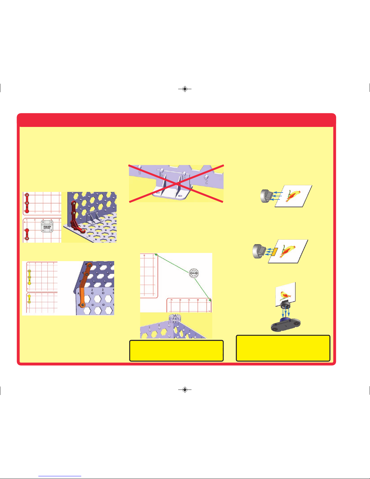
Another symbol of note is the base grid
support. It is important to pay attention to the
orientation of the part in the diagram since it is
not symmetrical. The figure below shows the
symbol with the narrow channel on top. This
corresponds to the 3D rendering showing the
base grid support orientation.
When inserting the base grid into the base grid
support, it is a good idea to insert an area on
the base grid that doesn’t have raised letters
or numbers. The raised text can interfere with
the insertion or cause a tight fit between the
base grid and base grid support.
To install the base grid support onto the base
grid, align the holes of the support with the
base grid pegs in the desired location on the
base grid and press down firmly on the base
grid support. Make sure that the base grid
support is fully seated on the base grid.
The stabilizer is used to connect base grids on
their corners or edges. With eight slots, the
stabilizer allows the base grids to be mounted
in increments of 45 degrees. To attach the
stabilizer to the base grid, simply align the
desired grooves in the stabilizer with the edges
of the base grids and press down. The figure
below shows how the stabilizer symbol is
presented in the manual and the 3D rendering
of the stabilizer mounted to two base grids.
Some projects use the illusion cards. Separate
them (if they came together), push one into the
Illusion card holder.
If at any point the
illusion cards become to
loose to stay in the card holder you can add a
small strip of paper to insure the card fits snug
in the holder.
Then push the holder onto the shaft of the
clear motor (M4).
How to Use SnapCircuits
®
-5-
Note: While building the projects, be careful not
to accidentally make a direct connection across
the battery holder (a “short circuit”), as this may
damage and/or quickly drain the batteries.
Note: Go to: www.snapcircuits.net/sc3dmeg
for interactive 3D pictures to help with
building the 3D circuits.
SC-3DMEG_Manual.qxp_SC-3Di_Manual_060816 6/19/17 7:30 PM Page 6
Page 7
-6-
How to Use SnapCircuits
®
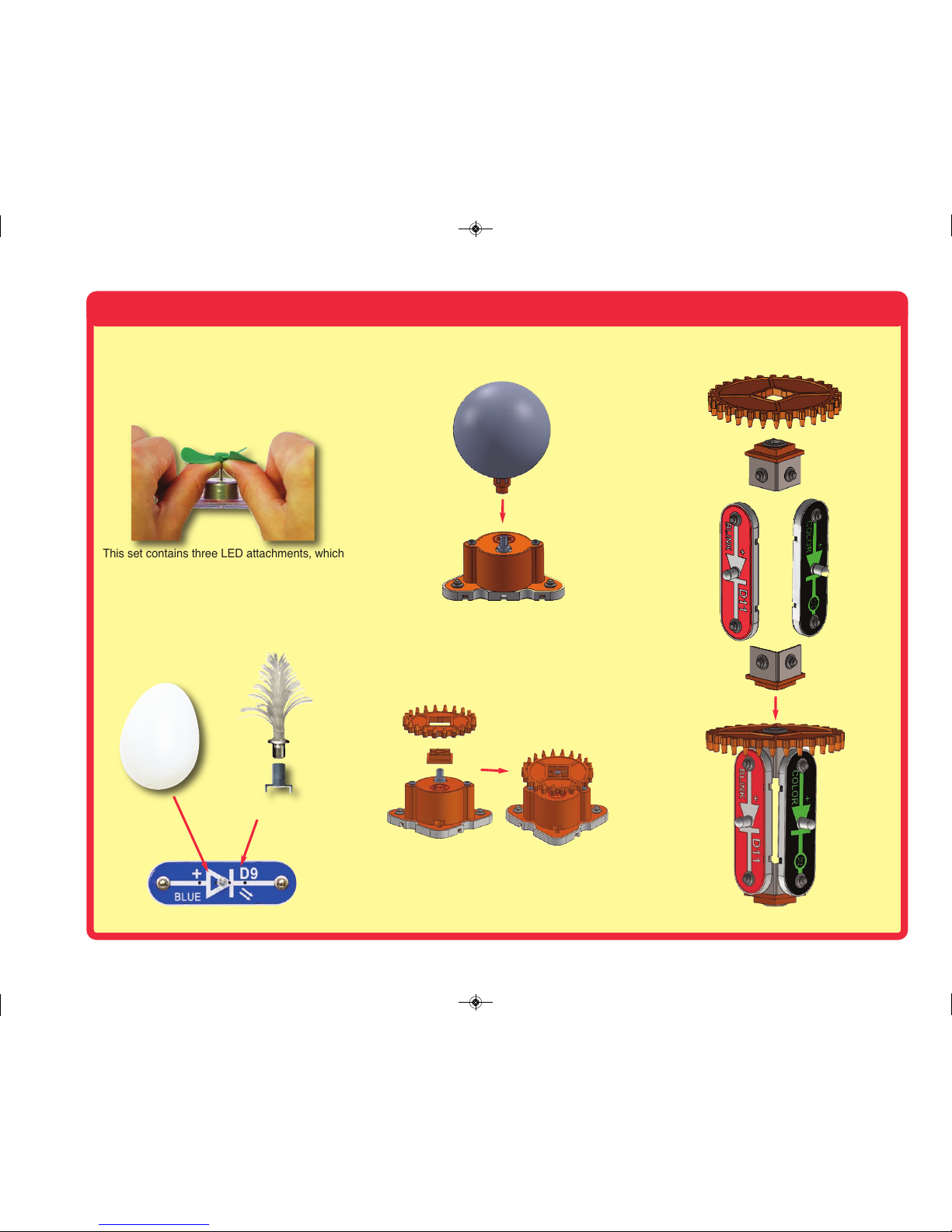
The clear motor (M4) will often have the wind
fan mounted on it; simply push the fan onto the
shaft. To remove it, push up on it with a
screwdriver or your thumbs, being careful not
to break it.
This set contains three LED attachments, which
can be mounted on the LED modules (D9, D11,
and D12) to enhance their light effects. The egg
attachment is mounted directly on the LEDs,
but
the fiber optic festive tree must be mounted
using the mounting base, as shown. This is
described in the projects.
In some
projects the mirror ball is placed on the orange
motor (M9).
In some projects a gear is mounted on the
orange motor using the gear insert.---
In some projects one or two components are
attached to a gear using the 3D snaps
Egg
Fiber Optic Festive
Tree
SC-3DMEG_Manual.qxp_SC-3Di_Manual_060816 6/19/17 7:30 PM Page 7
Page 8
About Your Snap Circuits
®
Parts
(Part designs are subject to change without notice).
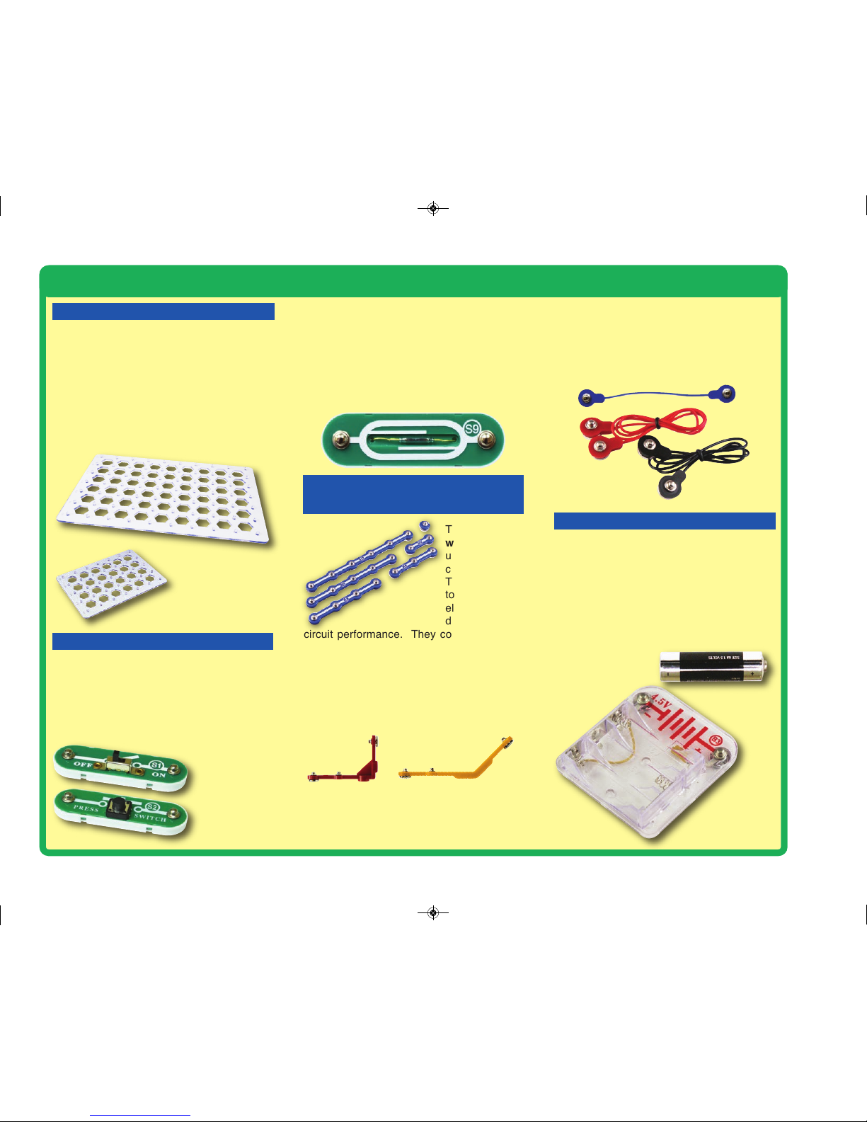
The base grids are platforms for mounting
parts and wires. They function like the printed
circuit boards used in most electronic
products, or like how the walls are used for
mounting the electrical wiring in your home.
This set has two sizes, which can be placed
together to form larger grids. One of the small
grids has pegs on both sides and 6 thru-snaps,
to allow assembly of circuits on both sides.
The slide & press switches (S1 &S2)
connect (pressed or “ON”) or disconnect (not
pressed or “OFF”) the wires in a circuit. When
ON they have no effect on circuit performance.
Switches turn on electricity just like a faucet
turns on water from a pipe.
The reed switch (S9) is an electrical switch
that can be controlled by a magnet. It has two
metal contacts close together. The magnetic
field from the magnet makes the contacts
come together, completing a circuit just like
other switches do.
The blue snap
wires are wires
used to connect
c o m p o n en ts.
They are used
to transport
electricity and
do not affect
circuit performance. They come in different
lengths to allow orderly arrangement of
connections on the base grid.
The vertical snap wires (V1) and 45 degree
vertical snap wires (V2) make connections
between two dimensions, allowing electricity to
go up a wall.
The jumper wires (red, black, & blue) make
flexible connections for times when using the
snap wires would be difficult. They also are
used to make connections off the base grid.
Wires transport electricity just like pipes are
used to transport water. The colorful plastic
coating protects them and prevents electricity
from getting in or out.
The batteries (B3) produce an electrical
voltage using a chemical reaction. This
“voltage” can be thought of as electrical
pressure, pushing electricity through a circuit
just like a pump pushes water through pipes.
This voltage is much lower and much safer
than that used in your house wiring.
Using more
batteries increases the “pressure”, therefore, more
electricity flows.
BASE GRID
SNAP WIRES, VERTICALSNAP
WIRES, & JUMPER WIRES
BATTERY HOLDER
SLIDE&PRESS SWITCHES
Battery Holder (B3)
REED SWITCH (S9)
Slide &Press
Switches
(S1 & S2)
-7-
SC-3DMEG_Manual.qxp_SC-3Di_Manual_060816 6/19/17 7:30 PM Page 8
Page 9
About Your Snap Circuits
®
Parts
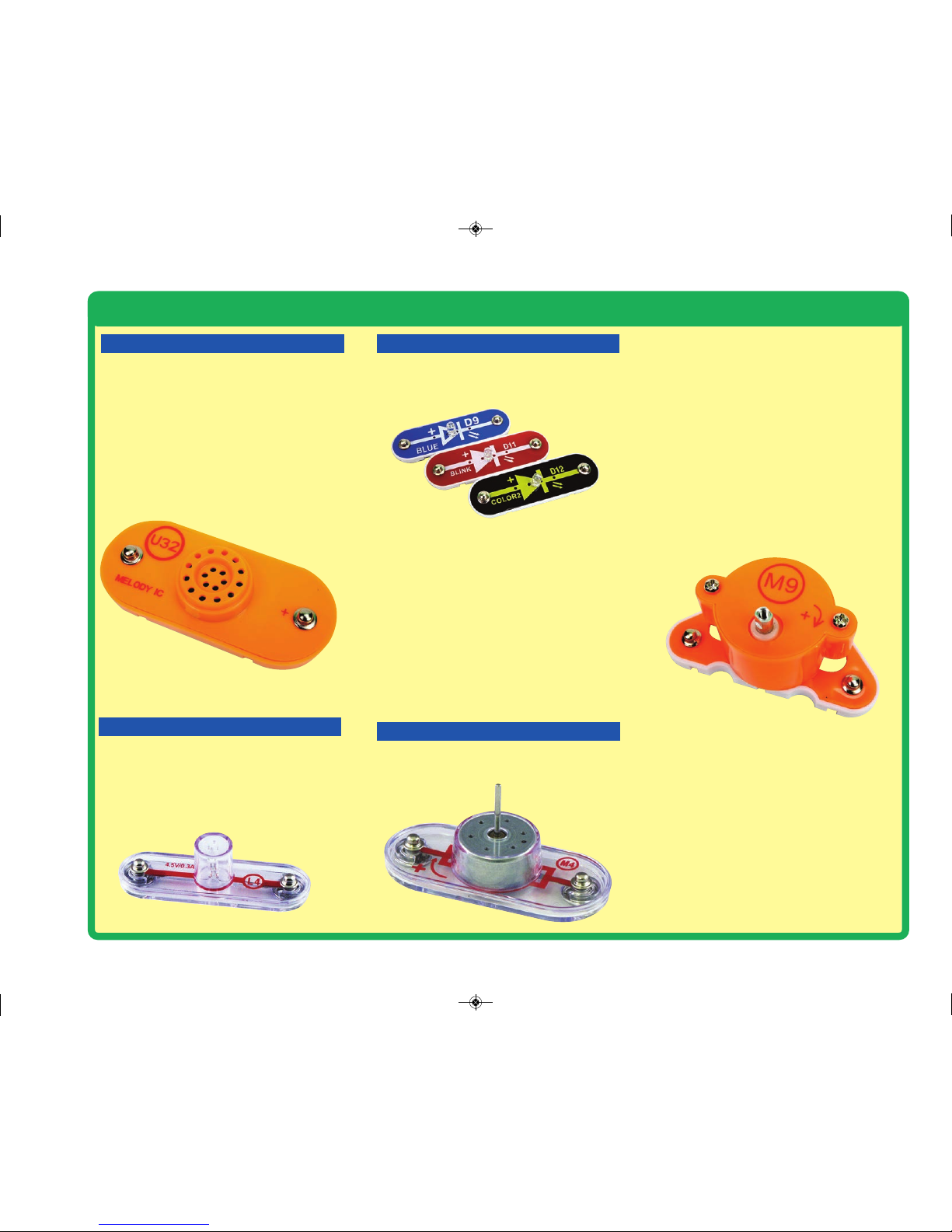
The melody IC(U32) contains a specialized
sound-generation integrated circuit (IC), a
small speaker, and a few supporting
components. The IC has a recording of the
melody, which it makes into an electrical signal
for the speaker. The speaker converts the
signal into mechanical vibrations. The
vibrations create variations in air pressure,
which travel across the room. You “hear”
sound when your ears feel these air pressure
variations.
A light bulb, such as in the 4.5V lamp (L4),
contains a special thin high-resistance wire.
When a lot of electricity flows through, this wire
gets so hot it glows bright. Voltages above the
bulb’s rating can burn out the wire.
The blue, blink red, and color2 LEDs (D9,
D11 & D12) are light emitting diodes, and may
be thought of as a special one-way light bulbs.
In the “forward” direction, (indicated by the
“arrow” in the symbol) electricity flows if the
voltage exceeds a turn-on threshold
brightness then increases. The blink red LED
contains a microcircuit that turns it on and off.
The color2 LED contains red, green, and blue
LEDs, with a micro-circuit controlling them. A
high current will burn out an LED, so the
current must be limited by other components
in the circuit (Snap Circuits
®
LEDs have
internal resistors added, to protect them in
case you make wiring mistakes). LEDs block
electricity in the “reverse” direction.
The clear motor (M4) converts electricity into
mechanical motion. An electric current
through the motor will turn the shaft. It can
also be used as a generator, since it produces
an electric current when the shaft is turned.
How does electricity turn the shaft in the
motor? The answer is magnetism. Electricity
is closely related to magnetism, and an electric
current flowing in a wire has a magnetic field
similar to that of a very, very tiny magnet.
Inside the motor are several coils of wire with
many loops. If a large electric current flows
through the loops, the magnetic effects
become concentrated enough to move the
coils. The motor has a magnet inside, so as
the electricity moves the coils to align them
with the permanent magnet, the shaft spins.
The orange motor (M9) is a motor with a built-
in gearbox. The gearbox makes the shaft spin
slower but with greater force. Do not try to spin
its shaft manually to generate electricity
because you may break it. The middle snap is
only used for mechanical stability.
SOUND MODULE
MOTORS
LEDs
LAMP
-8-
SC-3DMEG_Manual.qxp_SC-3Di_Manual_060816 6/19/17 7:30 PM Page 9
Page 10
Introduction to Electricity
What is electricity? Nobody really knows. We only know how to produce it,
understand its properties, and how to control it. Electricity is the movement of subatomic charged particles (called electrons) through a material due to electrical
pressure across the material, such as from a battery.
Power sources, such as batteries, push electricity through a circuit, like a pump
pushes water through pipes. Wires carry electricity, like pipes carry water. Devices
like LEDs, motors, and speakers use the energy in electricity to do things. Switches
and transistors control the flow of electricity like valves and faucets control water.
Resistors limit the flow of electricity.
The electrical pressure exerted by a battery or other power source is called
voltage and is measured in volts (V). Notice the “+” and “–” signs on the battery;
these indicate which direction the battery will “pump” the electricity.
The electric current is a measure of how fast electricity is flowing in a wire, just
as the water current describes how fast water is flowing in a pipe. It is expressed
in amperes (A) or milliamps (mA, 1/1000 of an ampere).
The “power” of electricity is a measure of how fast energy is moving through a
wire. It is a combination of the voltage and current (Power = Voltage x Current). It
is expressed in watts (W).
The resistance of a component or circuit represents how much it resists the
electrical pressure (voltage) and limits the flow of electric current. The relationship
is Voltage = Current x Resistance. When the resistance increases, less current
flows. Resistance is measured in ohms (W), or kilo ohms (kW, 1000 ohms).
Nearly all of the electricity used in our world is produced at enormous generators
driven by steam or water pressure. Wires are used to efficiently transport this
energy to homes and businesses where it is used. Motors convert the electricity
back into mechanical form to drive machinery and appliances. The most important
aspect of electricity in our society is that it allows energy to be easily transported
over distances.
Note that “distances” includes not just large distances but also tiny distances. Try
to imagine a plumbing structure of the same complexity as the circuitry inside a
portable radio - it would have to be large because we can’t make water pipes so
small. Electricity allows complex designs to be made very small.
There are two ways of arranging parts in a circuit, in series or
in parallel. Here are examples:
Placing components in series increases the resistance; highest
value dominates. Placing components in parallel decreases the
resistance; lowest value dominates.
The parts within these series and parallel sub-circuits may be
arranged in different ways without changing what the circuit
does. Large circuits are made of combinations of smaller series
and parallel circuits.
Series Circuit
Parallel Circuit
-9-
SC-3DMEG_Manual.qxp_SC-3Di_Manual_060816 6/19/17 7:30 PM Page 10
Page 11
DOs and DON’Ts of Building Circuits
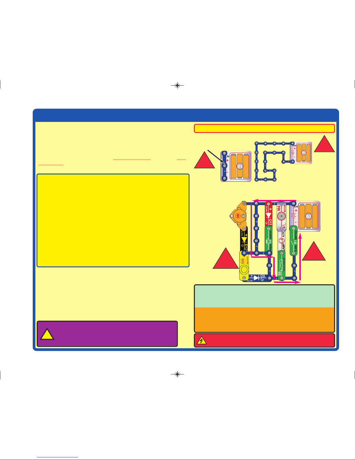
Placing a 3-snap wire directly
across the batteries is a
SHORT CIRCUIT.
This is also a
SHORT CIRCUIT.
When the slide switch (S1) is turned on, this large circuit has a SHORT
CIRCUIT path (as shown by the arrows). The short circuit prevents any
other portions of the circuit from ever working.
!
!
NEVER
DO!
NEVER
DO!
NEVER
DO!
!
NEVER
DO!
!
You are encouraged to tell us about new programs and circuits you create.
If they are unique, we will post them with your name and state on our
website at: www.snapcircuits.net/learning_center/kids_creation.
Send your suggestions to ELENCO
®
: elenco@elenco.com.
ELENCO®provides a circuit designer so that you can make your own Snap
Circuits®drawings. This Microsoft®Word document can be downloaded
from: www.snapcircuits.net/learning_center/kids_creation or through
the www.snapcircuits.net website.
Warning to Snap Circuits®owners: Do not connect
additional voltage sources from other sets, or you may
damage your parts. Contact ELENCO®if you have questions
or need guidance.
!
Examples of SHORT CIRCUITS - NEVER DO THESE!!!
WARNING: SHOCK HAZARD - Never connect Snap Circuits
®
to the electrical outlets in your home in any way!
After building the circuits given in this booklet, you may wish to experiment on your
own. Use the projects in this booklet as a guide, as many important design concepts
are introduced throughout them. Every circuit will include a power source (the
batteries), a resistance (which might be a motor, melody IC, or LED (which has an
internal protection resistor), etc.), and wiring paths between them and back.
You
must be careful not to create “short circuits” (very low-resistance paths across the
batteries, see examples below) as this will damage components and/or quickly drain
your batteries. Elenco®is not responsible for parts damaged due to incorrect
wiring.
Here are some important guidelines:
ALWAYS
USE EYE PROTECTION WHEN EXPERIMENTING ON YOUR OWN.
ALWAYS include at least one component that will limit the current through a
circuit, such as a motor, melody IC, or an LED (which has an internal
protection resistor).
ALWAYS use switches in conjunction with other components that will limit the
current through them. Failure to do so will create a short circuit
and/or damage those parts.
ALWAYS disconnect your batteries immediately and check your wiring if
something appears to be getting hot.
ALWAYS check your wiring before turning on a circuit.
NEVER connect to an electrical outlet in your home in any way.
NEVER leave a circuit unattended when it is turned on.
NEVER try to turn the shaft of the orange motor (M9) by hand or with tools, as
this may break it.
For all of the projects given in this book, the parts may be arranged in different
ways without changing the circuit. For example, the order of parts connected in
series or in parallel does not matter — what matters is how combinations of
these sub-circuits are arranged together.
3D Construction: Motors or other parts that produce motion (which you may
have from other snap Circuits
®
sets) should only be mounted overhead or on
walls with great care, as the vibrations they produce could cause them to fall.
The circuits in this set have been checked with the parts shown in them.
-10-
SC-3DMEG_Manual.qxp_SC-3Di_Manual_060816 6/19/17 7:30 PM Page 11
Page 12
Advanced Troubleshooting
(Adult supervision recommended)
Elenco®is not responsible for parts damaged due to incorrect
wiring.
If you suspect you have damaged parts, you can follow
this procedure to systematically determine which ones
need replacing:
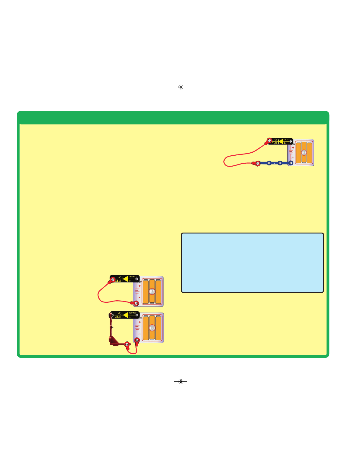
1. Lamp (L4), blue LED (D9), blink red LED(D11), color2 LED
(D12), melody IC(U32), and battery holder(B3):
Place
batteries in holder. Place the lamp directly across the battery
holder, it should light. Place the LEDs (D9, D11, & D12) directly
across the battery holder one at a time (LED + to battery +),
the LED should light (D11 should be blinking, and D12 should
slowly change colors). Place the melody IC directly across the
battery holder (+ to +), it should play a tune. If none work, then
replace your batteries and repeat, if still bad then the battery
holder is damaged.
2.
Clear motor (M4) and orange motor (M9): Place the clear
motor directly across the battery holder, the shaft should spin
(you can place the green fan on the shaft so the spinning is
easy to see). Place the orange motor directly across the battery
holder (note that the middle snap on the motor is not used), the
shaft should spin.
3.
Jumper wires: Use this mini-
circuit to test each jumper wire,
the lamp should light.
4.
Vertical snap wires (V1) and 45
degree vertical snap wires (V2):
Use this mini-circuit to test each of
the vertical snap wires (V1 & V2),
one at a time. The lamp should
light.
5.
Snap wires: Use this mini-circuit to test each of the snap
wires, one at a time. The lamp
should light.
6.
Slide switch (S1), press switch (S2), and reed switch (S9):
Build project 1; if the color2 LED (D12) doesn’t light then the
slide switch is bad. Replace the slide switch with the press
switch to test it. Replace the press switch with the reed switch
and hold the magnet near it to test it, there should be a magnet
position that turns on the LED, or the reed switch is bad.
ELENCO
®
150 Carpenter Avenue
Wheeling, IL 60090 U.S.A.
Phone: (847) 541-3800
Fax: (847) 520-0085
e-mail: help@elenco.com
Website: www.elenco.com
You may order additional / replacement parts at:
www.snapcircuits.net
-11-
SC-3DMEG_Manual.qxp_SC-3Di_Manual_060816 6/19/17 7:30 PM Page 12
Page 13

-12-
Project # Description Page #
1 Color Light 14
2 Blue Light 14
3 Red Light 14
4 Lamp Light 15
5 Play a Melody 15
6 Fun Seven 15
7 Rotation light 16
8 Rotation Lights 16
9 Fan 16
10 Suction Fan 16
11 Mirror Ball 16
12 Spinning Horizontal Lights 17
13 Ceiling Light 19
14 Efficient Ceiling light 21
15 Ceiling Speaker 21
16 Ceiling Fan 21
17 Four Lights 21
18 Lights & Sound 21
19 Lights & Motion 21
20 Festive House 22
21 Gears 23
22 Inverse Gear Ratio 23
23 Reed Switch 24
24 Magnet Controlled Sound 24
25 Magnet Controlled Motor 24
26 An Optical Illusion 24
27 More Optical Illusions 24
28 Funky Blinking Lights 25
Project # Description Page #
29 Funky Sounds 25
30 Low Funky Sounds 25
31 Variable Speed Fan 25
32 New Speed Fan 25
33 Any Angle LEDs 26
34 Any Angle LEDs Variants 26
35 Super Spinning Magnet 27
36 Spinning Vertical Lights 28
37 Faster Spinning Vertical Lights 28
38 Vaulted Ceiling House 29
39
Vaulted Ceiling House with Roof Lights 30
40 Box Cover Circuit 31
41 Disco Effects 33
42 Disco Effects (II) 34
43 Overhead Lights 35
44 Overhead Lights & More 36
45 Lifting 37
46 Windmill 38
47 Mini Windmill 38
48 Tall Angled Roof House 39
49 Tall Angled Roof House Variants 41
50
Enhanced Tall Angled Roof House
41
51
Enhanced Tall Angled Roof House Variants
41
52 House with Doorbell 42
53 Festive House with Roof Lights 43
54 Chandelier Circuit 45
55 Quiet Chandelier Circuit 46
56 Indoor & Outdoor Lights 47
Project # Description Page #
57 Indoor & Outdoor 48
58 Disco Lights 49
59 Angled Disco Projector 49
60 Both Sides Lights 50
61 Quiet Both Sides Lights 50
62 Spinning Magnet 50
63 Disco Spotlight 51
64 Spotlight 51
65 Spin the Magnet 51
66 2-Speed Mirror Ball 52
67 2-Speed Fan 52
68 Musical Mirror Ball 52
69 Musical Fan 52
70 Tree House 53
71 Brighter Tree House 54
72 Blue Tree House 54
73 Highlighted Tree House 55
74 Blinking Tree House 55
75 Egg House 55
76 Silent Tree House 55
77 Tree House with Fan 55
78 Manual Rotation Vertical Lights 56
79
Manual Rotation Vertical Lights Variants
79
80 Stay with the Magnet 56
81 Ceiling Disco Ball 57
82 Rotating Field 59
83 Flash & Sound 59
84 Lifter 60
Project Listings
SC-3DMEG_Manual.qxp_SC-3Di_Manual_060816 6/19/17 7:30 PM Page 13
Page 14

-13-
Project Listings
Project # Description Page #
85 Fast Lifter 61
86 Magnet Fan 61
87 Fast Magnet Fan 61
88 45° LEDs 61
89 Pivot LED bar 61
90 Side Ways 62
91 Side Ways 2 62
92 Swing LEDs 63
93 Swing LEDs ? 63
94 Follow the Field 63
95 Rocking Switch 64
96 Disco Ball Switch 64
97 Disco Ball Melody 64
98 Rocking Switch LEDs 64
99 Speed Change 65
100 Fan Power 65
101 Fan Power 2 65
102 Door Bell 66
103 Door Bell Lights 66
104 Fan Speed 66
105 Disco Ball Switch 66
106 Fan Speed 67
107 Manual Fan Speed 67
108 Fan Speed 2 67
109 Mirror Ball Speed Control 68
110 Mirror Ball Speed Control (II) 68
111 Mirror Ball Speed Control (III) 68
112 Fan Speed Control 68
Project # Description Page #
113 Illusion Card Speed Control 68
114 Generator 69
115 Generator 2 69
116 Water Completes the Circuit 69
117 You Complete the Circuit 69
118 Arrow LEDs 70
119 Arrow Melody 70
120 Light Stairs 71
121 Light Stairs 2 71
122 Egg Head 72
123 Robot 72
124 Plane 73
125 Mini Plane 74
126 Music Mini Plane 74
127 Triple Series 75
128 Triple Parallel 75
129 AND Circuit 76
130 OR Circuit 76
131 Back EMF 77
132 EMF 2 77
133 Lamp & Fan Independent 77
134 LEDs in Series 78
135 LEDs in Parallel 78
136 Cross Over 78
137 Cross Over Tree 78
138 Lighted Cross 79
139 Green Dot 79
140 2-Sided Grid 79
Project # Description Page #
141 Wall Fan 80
142 Wall Fan 2 80
143 Green Light Ball 80
144 Showcase 81
145 Current Law 82
146 Two Pull Power 82
147 On Off 83
148 On Off 2 83
149 Twice On Off 83
150 Twice On Off 2 83
151 Twice On Off 3 83
152 Compass 84
153 Downdraft 85
154 Strobe 87
155 Super Spotlight 88
156 Super Spotlight (II) 88
157 Tower 89
158 Mega Tower 90
159 Super Tower 91
160 Spinning Reed Switch 92
161 Spinning Reed Switch 2 92
162 Spinning Reed Switch 3 92
163 Spinning Reed Switch 4 92
B1 Bonus Spinning Mirror Beeper 93
B2
Bonus Spinning Mirror Beeper 90°
94
B3 Bonus Blinking Lamp 94
B4 Bonus Reflection Light 95
B5 Bonus House with Loft 95
SC-3DMEG_Manual.qxp_SC-3Di_Manual_060816 6/19/17 7:30 PM Page 14
Page 15
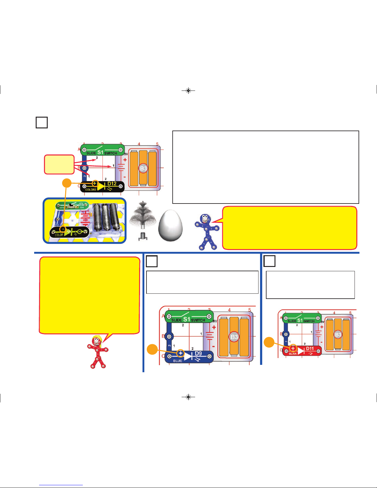
Project 1
Color Light
Snap Circuits®uses electronic blocks that snap onto a clear plastic base grid to build
different circuits. These blocks have different colors and numbers on them so you can
easily identify them. This set contains both large (11” x 7.7”) and small (7.7” x 5.5”) base
grids; you may use either size for this small circuit.
Build the circuit shown on the left by placing all the parts with a black 1 next to them on
the base grid first. Then, assemble parts marked with a 2. Install three (3) “AA” batteries
(not included) into the battery holder (B3) if you have not done so already; be sure the
battery springs are compressed straight back, and not bent up, down, or to one side.
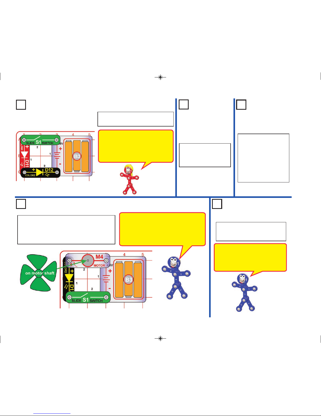
Turn on the slide switch (S1), and enjoy the light show from the color2 LED (D12). For
best effects, place one of the LED attachments (fiber optic festive tree or egg), and dim
the room lights. The fiber optic festive tree must be used with its mounting base.
+
Project 2 Blue Light
Modify the preceding circuit by replacing the color2
LED (D12) with the blue LED (D9), as shown. The
blue LED is brighter, but does not change colors.
Modify the preceding circuit by replacing
the blue LED (D9) with the blink red
LED (D11), as shown. The blink red
LED flashes about once a second.
Project 3 Red Light
Snappy says when you turn on the slide switch,
electricity flows from the batteries, through the
color LED and back to the battery through the
switch. If the switch is off, the flow of electricity is
blocked, and the color2 LED won’t light.
LEDs are light emitting diodes, which convert
electrical energy into light. The color of the light
depends on the characteristics of the material used
in them. The color2 LED actually contains separate
red, green, and blue lights, with a micro-circuit
controlling them; the colors can be combined to
produce yellow, cyan, purple, and white.
NOTE: this circuit (and many others in this book) have an LED
being used without a resistor or other component to limit the
electric current through it. Normally this could damage an LED but
your Snap Circuits
®
LEDs include internal protection resistors, and
will not be damaged. Be careful if you later use other electrical sets
with unprotected LEDs.T he festive tree and egg may also be used
with other Snap Circuits® LEDs from different sets.
+
Placement
Level
Numbers
LED Attachments
+
-14-
SC-3DMEG_Manual.qxp_SC-3Di_Manual_060816 6/19/17 7:30 PM Page 15
Page 16
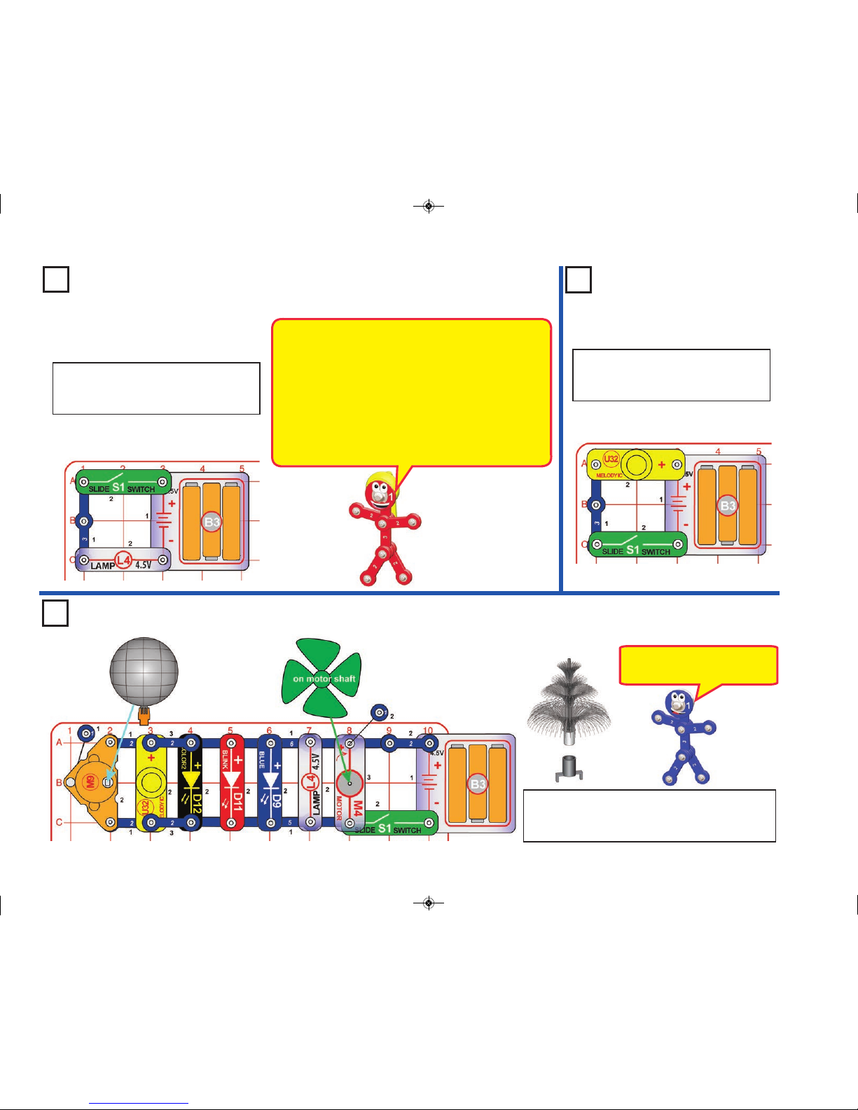
Project 4 Lamp Light
Modify the preceding circuit to be this
one. Turn on the slide switch (S1) to light
the lamp (L4).
The lamp (L4) converts electricity into light. It is an
incandescent light bulb, just like other incandescent bulbs
in homes except smaller. In an incandescent bulb
electricity heats up a high-resistance wire until it glows,
producing light. Incandescent light bulbs are very
inefficient, converting less than 5% of the electricity used
into light, with the rest becoming heat.
LEDs are much more efficient than incandescent light
bulbs, and are increasingly being used for home lighting
and flashlights.
Project 5
Play a Melody
Build this circuit, then turn on the slide
switch (S1) to play a melody with the
melody IC (U32).
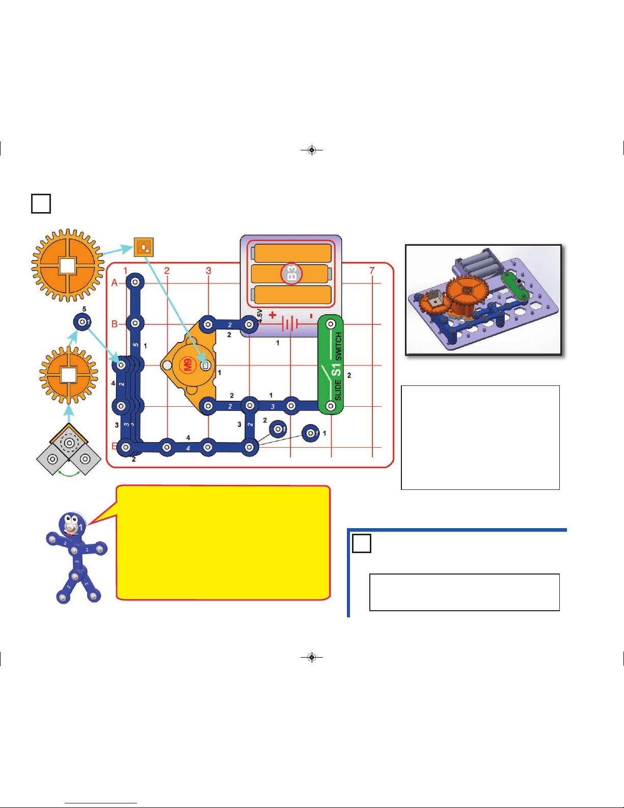
Project 6
Build the circuit shown, and place the fiber optic festive
tree in its mounting base and on the blink red LED (D11).
Turn on the slide switch (S1) and enjoy the show.
This circuit has four lights, 2 motors,
and music. Lights, sound, & motions!
-15-
Fun Seven
SC-3DMEG_Manual.qxp_SC-3Di_Manual_060816 6/19/17 7:30 PM Page 16
Page 17
Project 7 Rotation Light
Build the circuit as shown; it has
two 3D snaps mounted on two 90
degree vertical snap wires (V1),
and then the color2 LED (D12) is
mounted on the 3D snaps.
Turn on the circuit and the color2
LED lights. Rotate the LED to any
position.
You can replace the color2 LED
with the blue LED (D9), blink red
LED (D11), or lamp (L4).
Note: if the LED assembly fit seems
loose, add a 1-snap wire between
one of the 3D snaps and a V1.
+
Use the preceding circuit
but add a second light
(blue LED (D9), blink red
LED (D11), or lamp (L4)) to
the female snaps on the
3D snaps, as shown. The
“+” side of the LEDs should
be oriented to the right.
Project 8
Rotation
Lights
The 3D snaps enable
you to rotate a light to
any position.
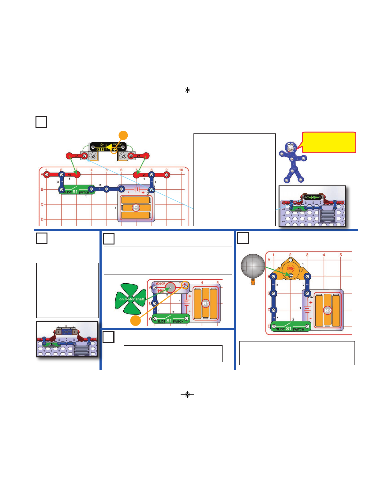
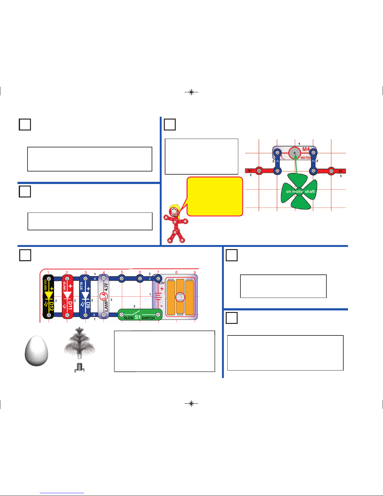
Project 9 Fan
Build the circuit and place the wind fan on the clear motor
(M4). Turn on the slide switch (S1) to spin the fan. Place
your hand near the fan without touching it, and you can feel
air being blown up towards you.
+
Project 10 Suction Fan
Use the preceding circuit but reverse the clear
motor (M4). Now the fan sucks air downward.
Project 11 Mirror Ball
Build the circuit and place the mirror ball on the
orange motor (M9). Turn on the slide switch (S1) to
spin the mirror ball.
-16-
SC-3DMEG_Manual.qxp_SC-3Di_Manual_060816 6/19/17 7:30 PM Page 17
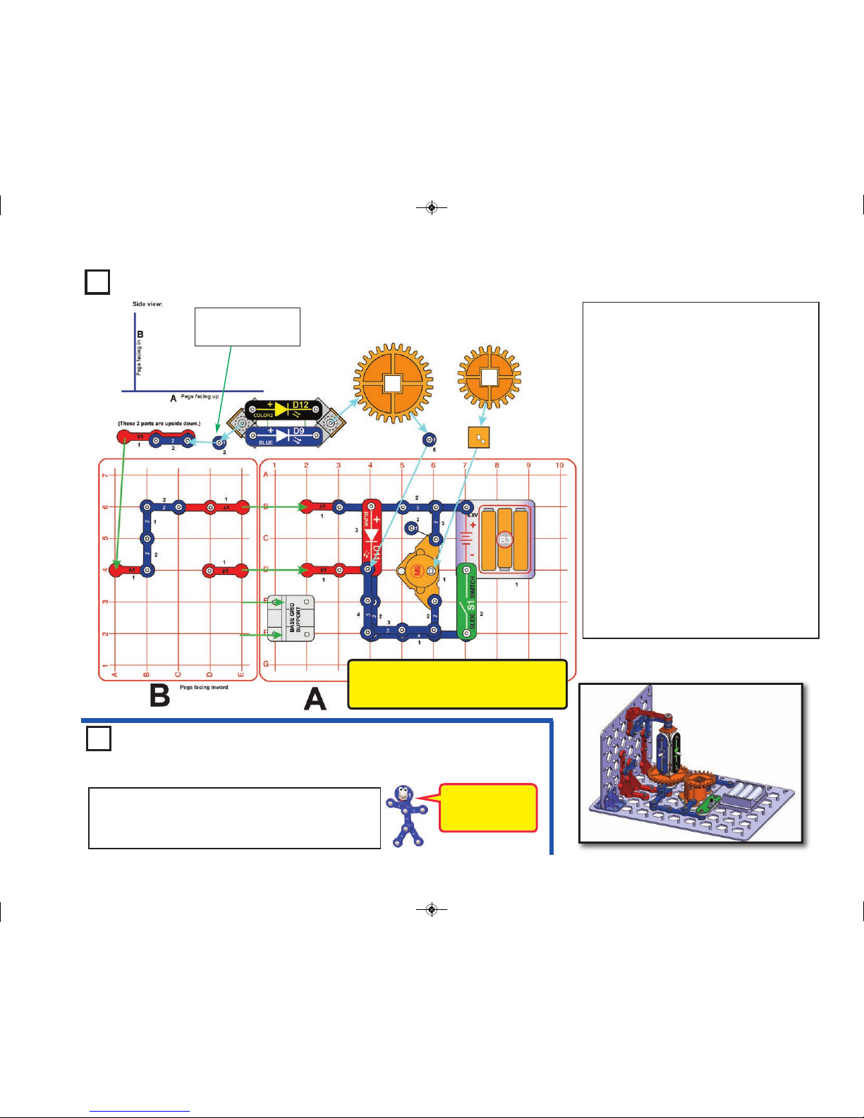
Page 18
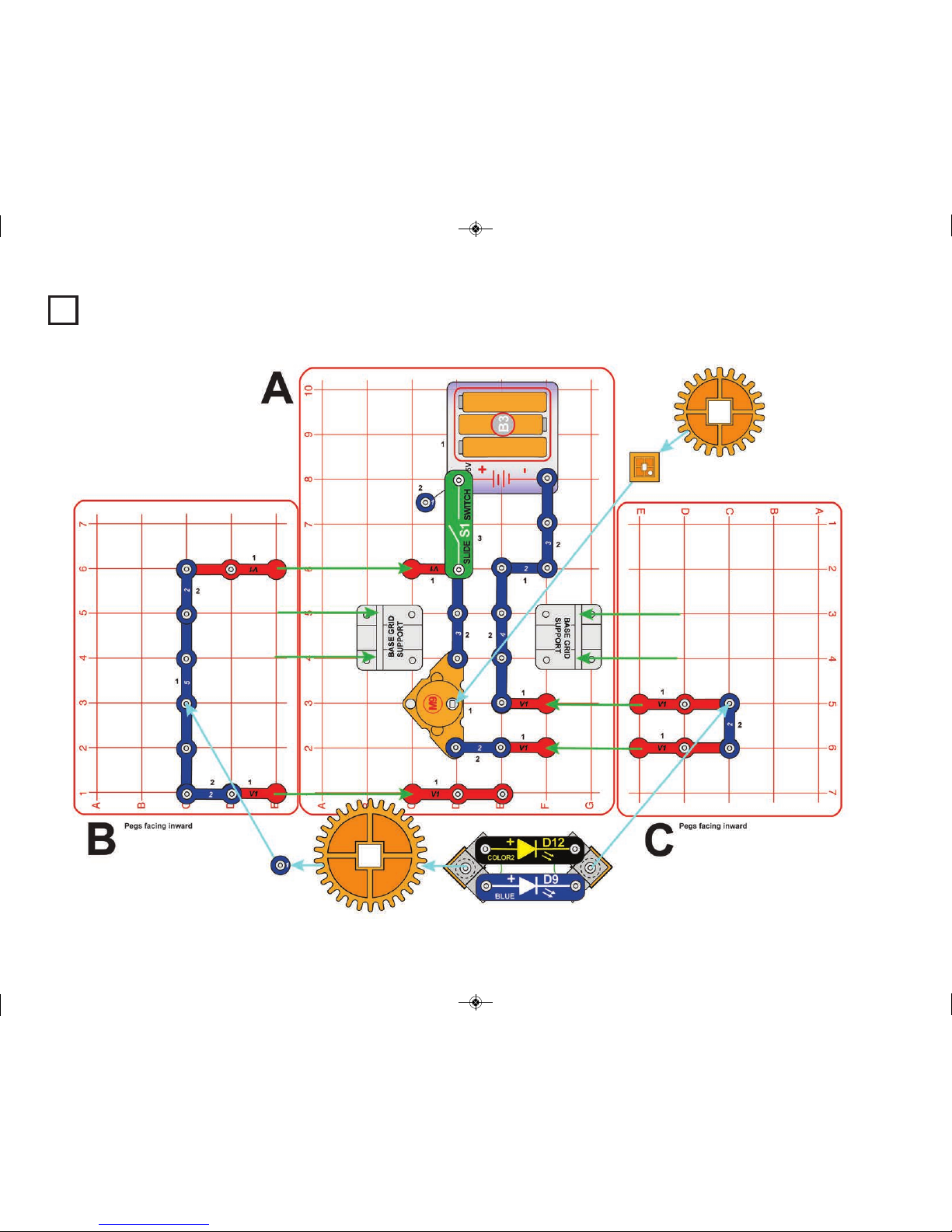
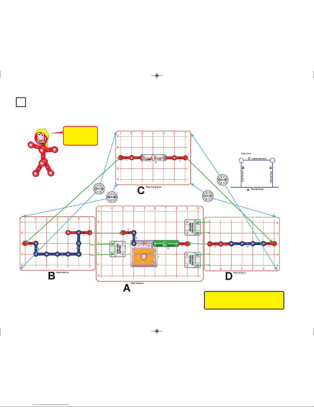
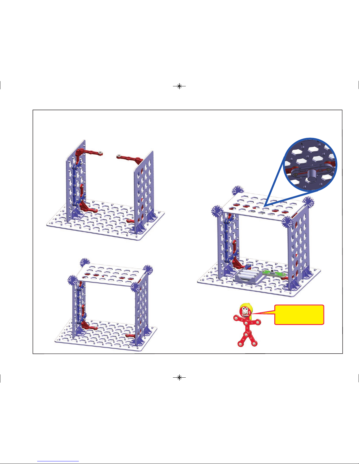
Project 12 Spinning Horizontal Lights
-17-
SC-3DMEG_Manual.qxp_SC-3Di_Manual_060816 6/19/17 7:30 PM Page 18
Page 19

Assembly (adult supervision recommended):
1. Place base grid supports and orange motor (M9) on base grid A.
Place the small gear on the gear insert and mount on the orange
motor. The teeth on the gear should face up.
2. Mount the blue & color2 LEDs (D9 & D12) to the 3D snaps, and
attach the large gear and a 1-snap wire, as shown. The teeth on the
gear should face the LEDs, and the “+” side of the LEDs should be
towards the gear.
3. Mount parts on grids B & C, and install in base grid supports in grid
A. The pegs should be facing inward.
4. Mount the LED assembly from step 2 between the 5-snap wire on
grid B and the 2-snap wire on grid C, as shown. The teeth on the large
and small gears should align.
5. Place remaining parts on grid A.
Turn on the slide switch (S1). The color2 and blue LEDs should light,
and be rotated by the gears.
Note: If the gears do not rotate properly, you may get better
performance if you spread the tops of the mini base grids apart. You
can do this by adding another base grid as a “roof” and securing with 4
stabilizers, as done in project 20.
-18-
Note: Go to: www.snapcircuits.net/sc3dmeg
for interactive 3D pictures to help with
building the 3D circuits.
SC-3DMEG_Manual.qxp_SC-3Di_Manual_060816 6/19/17 7:30 PM Page 19
Page 20
Project 13
-19-
Ceiling Light
Think of this circuit
as a room with a
ceiling light fixture.
Note: Go to: www.snapcircuits.net/sc3dmeg
for interactive 3D pictures to help with
building the 3D circuits.
SC-3DMEG_Manual.qxp_SC-3Di_Manual_060816 6/19/17 7:30 PM Page 20
Page 21
-20-
Assembly (adult supervision recommended):
1. Place base grid supports on base grid A.
2. Place parts on base grids B, & D, and install into base grid supports
on grid A. The pegs should be facing inward.
3. Mount grid C on top of grids B & D using 4 stabilizers, attaching the 2
90 degree vertical snap wires (V1) as you do it.
4. Place the remaining parts on grids A & C.
Turn on the slide switch (S1) to light the 4.5 Lamp (L4).
Underside
view
LEDs are increasingly
being used for room
lighting.
SC-3DMEG_Manual.qxp_SC-3Di_Manual_060816 6/19/17 7:30 PM Page 21
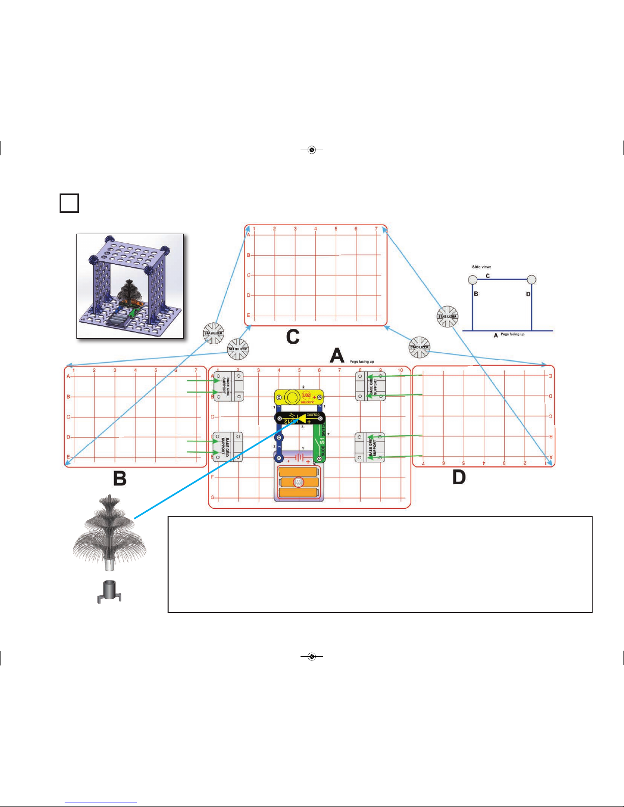
Page 22
-21-
Project 17
Four Lights
Build the circuit shown and turn on the slide
switch (S1). For best effects, place one of the
LED attachments (fiber optic festive tree or
egg), and dim the room lights. The fiber optic
festive tree must be used with its mounting
base.
Project 18
Lights & Sound
Use the preceding circuit but replace
one of the lights with the melody IC
(U32, “+” towards the 6-snap wire).
Project 19
Lights & Motion
Use either of the preceding circuits but replace one
of the lights with the clear motor (M4), and place the
green fan on the motor. Don’t place the motor next
to the melody IC (U32), and be sure that the fan
won’t hit any of the LED attachments.
Use the preceding circuit, but carefully replace the lamp
(L4) with the blue or color2 LED (D9 or D12, “+” to the
right).
Project 14
Efficient Ceiling Light
Use the preceding circuit, but carefully replace the LED
with the melody IC (U32, “+” to the right).
Project 15
Ceiling Speaker
Project 16 Ceiling Fan
Use the preceding circuit, but
replace the melody IC with the
clear motor, wind fan, and two
2-snap wires, mounted as
shown here.
The added 2-snaps help
to secure the clear motor
to the ceiling, otherwise
the vibration it produces
might cause it to come
loose and fall.
SC-3DMEG_Manual.qxp_SC-3Di_Manual_060816 6/19/17 7:30 PM Page 22
Page 23
-22-
Festive House
Assembly:
1. Place base grid supports on base grid A.
2. Install grids B & D into base grid supports on grid A. The pegs can be pointed in either direction.
3. Mount grid C on top of grids B & D using 4 stabilizers.
4. Place the remaining parts on grid A. Place the fiber optic festive tree on the color2 LED (D12) using the mounting base.
Turn on the slide switch (S1) to light the color2 LED and play a tune on the melody if (U32). This circuit looks best in a dark
room. The melody IC may be removed if desired.
Project 20
SC-3DMEG_Manual.qxp_SC-3Di_Manual_060816 6/19/17 7:30 PM Page 23
Page 24
Project 21
Build the circuit as shown. The large gear
is placed on the gear insert and mounted
on the orange motor (M9), and the small
gear is placed on a 3D snap which is
mounted on a stack of snap wires (a 5-snap
on level 1, 3-snaps on levels 2 and 3, a 2snap on level 4, and a 1-snap on level 5).
The teeth should be pointed up on both
gears. Turn on the slide switch (S1) to spin
the gears.
Gears can be used to make things spin faster or slower.
When one gear has more teeth than another, it will spin
slower. Using gears to reduce rotation speed also increases
the turning force, allowing it to overcome more friction. Using
gears also changes the direction of rotation.
Inside the orange motor (M9) is a motor spinning very fast,
but with little force (too little to spin both orange gears).
Several small internal gears connect the internal motor to
the metal shaft that you see; these reduce the rotation
speed, give the shaft enough force to spin the orange gears,
and also make it easier to control.
Project 22
Inverse Gear Ratio
Use the preceding circuit but swap the locations of
the large and small gears. Now the 3D snap spins
more slowly.
Gears
-23-
SC-3DMEG_Manual.qxp_SC-3Di_Manual_060816 6/19/17 7:30 PM Page 24
Page 25

An Optical Illusion
Build the circuit, and place one of the illusion
cards in the illusion card holder, and place it
on the clear motor (M4). Turn on the slide
switch (S1), then push the press switch
(S2). The motor should be spinning the
illusion card, making the pictures on each
side appear to blend together.
The motor speed will vary a little depending
on the color of the color2 LED (D12) light.
Push the press switch again if you want to
speed up the motor.
If the illusion card comes out at high speed
then insert a small piece of paper into the
cardholder with the illusion card to make it
fit more snugly. see on page 6.
Project 27
More Optical
Illusions
Use the preceding circuit but try
the other 3 illusion cards. Also
try replacing the color2 LED
(D12) with the blink red LED
(D11) for different effects. If you
have a color LED (D8) from
another Snap Circuits® set,
then you can use it in place of
the LED in this circuit. D8
changes the motor speed in
bursts, giving some different
effects.
Project 25
Magnet Controlled
Motor
Use the preceding circuit but replace the melody IC (U32)
with the clear motor (M4) with green fan, or the orange
motor (M9, use a 1-snap wire to support its 3rd snap) with
the mirror ball. Use the magnet to activate the reed switch
and spin the motor.
Project 24
Magnet Controlled
Sound
Use the preceding circuit but replace the color2 LED
(D12) with the melody IC (U32, “+” on left). Use the
magnet to activate the reed switch and play a tune.
Build the circuit, and hold the magnet next to the reed
switch (S9) to turn on the color2 LED (D12). Move the
magnet around to turn the switch and LED on and off.
If you listen closely you may hear the reed switch
turning on or off. You can replace the color2 LED with
the lamp (L4) or the other LEDs (D9 or D11).
Project 23 Reed Switch
-24-
Project 26
The reed switch (S9) is an electrical
switch that can be controlled by a
magnet. It has two metal contacts
close together. The magnetic field
from the magnet makes the contacts
come together, completing a circuit
just like a switch does. If you look at
the reed switch contacts with a
magnifying glass then you may be
able to see them move slightly when
the magnet turns the reed switch on
and off.
SC-3DMEG_Manual.qxp_SC-3Di_Manual_060816 6/19/17 7:30 PM Page 25
Page 26
Project 28 Funky Blinking Lights
Build the circuit and turn on the slide switch
(S1). The LEDs (D11 & D12) are blinking.
Notice that when the blink red LED (D11) is on,
the brightness of the color2 LED (D12) is lower,
because the voltage from the batteries is
divided between the two LEDs. When the blink
red LED is off, the color2 LED gets the full
battery voltage, and gets brighter.
Project 29
Use the preceding circuit
but replace the color2 LED
(D12) with the melody IC
(U32, “+” on left).
Project 31 Variable Speed Fan
Build the circuit, place the wind fan on the motor
(M4), and turn on the slide switch (S1). The fan
speed varies a little depending on the color of the
color2 LED (D12). If the fan does not start spinning
then give it a push.
The clear motor (M4) and color2 LED (D12) are connected
in series, so the voltage from the batteries is divided
between them. The electricity used by the color2 LED
varies a little depending on the color of light it is producing.
When the color2 LED uses more electricity, there is less
electricity for the motor, and the motor slows down.
Project 32
Use the preceding circuit but replace
the color2 LED (D12) with the blue
(D9) or the blink red LED (D11).
The clear motor (M4) does not spin at full
speed because the LED is connected in
series with it. With the blink red LED, the
motor speeds up a little when the LED is
off, but it is hard to see the difference.
Project 30
Use the preceding circuit
but replace the blink red
LED (D11) with the color2
LED (D12). The sound will
vary depending on the
color of the color2 LED,
but will not be very loud
and sometimes there may
be no sound at all.
Funky Sounds
Low Funky
Sounds
New Speed Fan
-25-
SC-3DMEG_Manual.qxp_SC-3Di_Manual_060816 6/19/17 7:30 PM Page 26
Page 27
Project 33 Any Angle LEDs
Assembly (adult supervision recommended):
1. Place base grid supports on base grid A.
2. Mount parts on grids B & C, and install in base grid supports in
grid A. The pegs should be facing inward.
3. Place remaining parts on grid A.
4. Mount the blue & color2 LEDs (D9 & D12) to the 3D snaps,
connect 1-snap wires on both sides, and attach to the parts on grids
B & C, as shown. The “+” side of the LEDs should be towards grid C.
Turn on the slide switch (S1). The color2 and blue LEDs light; rotate
them to any position. The circuit looks best in a dimly lit room.
Use the preceding circuit but
replace the blue or color2 LEDs
with the blink red LED (D11),
lamp (L4), or melody IC (U32
“+”
on right
). You may also remove
one of the lights.
Project 34
Any Angle LEDs
Variants
-26-
Note: If the LED
assembly fit seems tight,
remove this 1-snap wire.
SC-3DMEG_Manual.qxp_SC-3Di_Manual_060816 6/19/17 7:30 PM Page 27
Page 28
Project 35 Super Spinning Magnet
Assembly:
1. Place base grid supports on base grid A.
2. Mount parts on grid B (except the blue jumper wire),
and install in base grid supports in grid A. The pegs should
be facing inward.
3. Place remaining parts on grid A, including the blue
jumper wire. Note that the color LED (D12) and lamp (L4)
are mounted on the 3D snaps, which are then mounted on
the 90 degree vertical snap wires (V1).
4. Place the gear insert on the shaft of the orange motor
(M9) and place the magnet on it, centered so it balances.
Turn on the slide switch (S1). The color2 LED (D12) and
lamp (L4) light; rotate their position as
desired. The orange motor spins the magnet, and the blue
LED (D9) lights when the reed switch (S9) is triggered by
the magnet.
If desired, swap the locations of the LEDs and lamp, or
replace one with the blink red LED (D11).
Note: if the LED assembly fit seems loose, add a 1-snap
wire between one of the 3D snaps and a V1.
-27-
SC-3DMEG_Manual.qxp_SC-3Di_Manual_060816 6/19/17 7:30 PM Page 28
Page 29
-28-
Project 37
Faster Spinning Vertical Lights
Project 36
Spinning Vertical Lights
Assembly (adult supervision recommended):
1.
Place base grid support on base grid A.
2. Place parts on grid B, and install into base grid
support on grid A. The pegs should be facing inward.
Also attach the 2-snap wire to the 90 degree vertical
snap wire (V1) that hangs off the top of grid B.
3. Mount the blue & color2 and LEDs (D9 & D12) to the
3D snaps, and attach the large gear and two 1-snap
wires on opposite sides, as shown. The teeth on the
gear should face the LEDs, and the “+” side of the LEDs
should be away from the gear.
4. Place the remaining parts on grid A. Place the small
gear in the gear insert and mount on the orange motor
(M9); the teeth on the gear should face up.
5. Mount the LED assembly from step 3 between the 2snap wire that hangs upside down and the 3-snap wire
on level 4 on grid A, as shown. The teeth on the large
and small gears should align.
Turn on the slide switch (S1). The color2 and blue LEDs
should light, and be rotated by the gears. The blink red
LED (D11) is blinking (and providing mechanical
stability).
Use the preceding circuit, but carefully swap the gears, so that
the larger gear is on the motor and the small gear is on the 3D
snap. The LEDs spin faster now, but the circuit may fall apart
too easily.
The circuit is more
stable when the gears
spin slowly.
Note: Go to: www.snapcircuits.net/sc3dmeg
for interactive 3D pictures to help with
building the 3D circuits.
Note: If the LED
assembly fit seems tight,
remove this 1-snap wire.
SC-3DMEG_Manual.qxp_SC-3Di_Manual_060816 6/19/17 7:30 PM Page 29
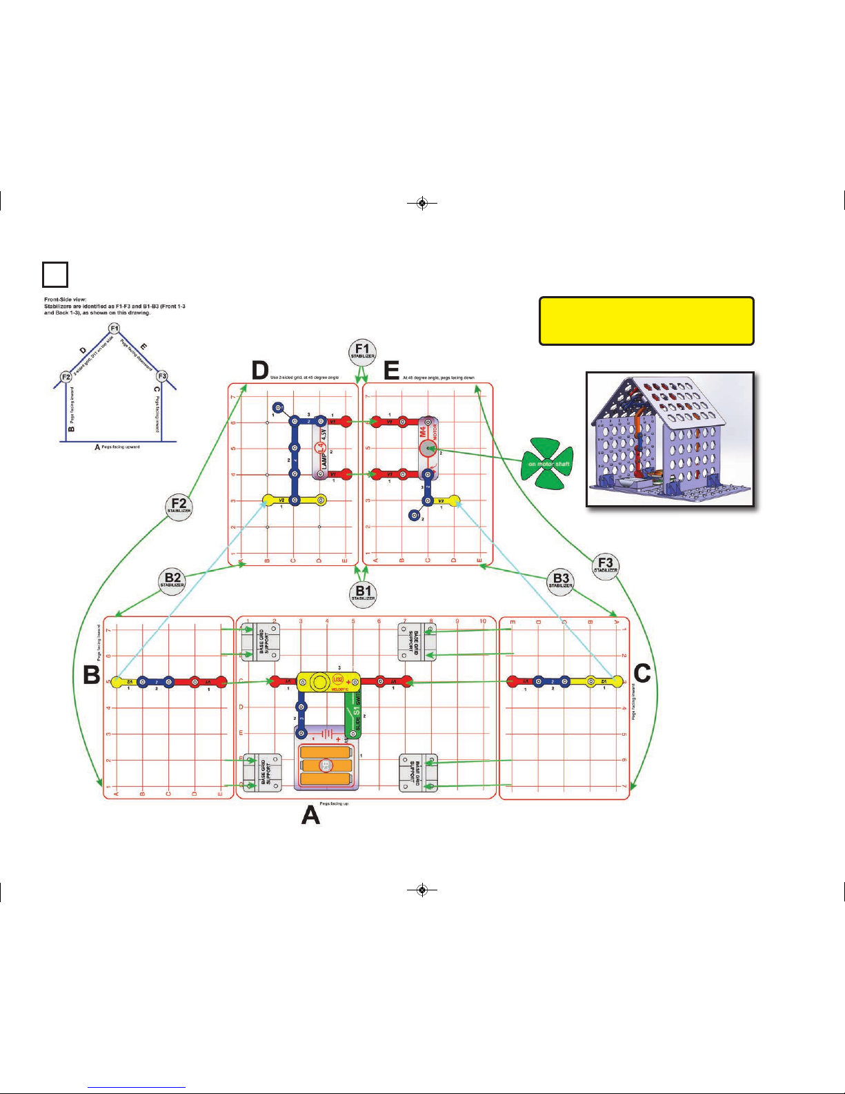
Page 30
-29-
Project 38
Vaulted Ceiling House
Note: Go to: www.snapcircuits.net/sc3dmeg
for interactive 3D pictures to help with
building the 3D circuits.
SC-3DMEG_Manual.qxp_SC-3Di_Manual_060816 6/19/17 7:30 PM Page 30
Page 31

-30-
Assembly (adult supervision highly recommended):
1. Place base grid supports on base grid A.
2. Mount parts on grids B & C and install in base grid supports in grid A.
The pegs should be facing inward. Do not use the double-sided grid.
3. Place remaining parts on grid A.
4. Mount grids D & E at the angles shown and with pegs facing down, on
top of grids B & C using six stabilizers, attaching the two angled snap
wires (V2) and two 90 degree vertical snap wires (V1) as you do it. Note
that grid D is the double-sided grid. Adjust the positions of the stabilizers
as needed.
5. Add the remaining parts on grids D & E.
Turn on the slide switch (S1). The clear motor (M4) spins a ceiling fan,
the melody IC (U32) plays a tune, and the lamp (L4) lights.
Use the preceding circuit, but carefully add parts on the top side of grid
D, as shown. If desired place the LED attachments on the LEDs.
Project 39
Vaulted Ceiling House
with Roof Lights
LED
Attachments
SC-3DMEG_Manual.qxp_SC-3Di_Manual_060816 6/19/17 7:30 PM Page 31
Page 32

-31-
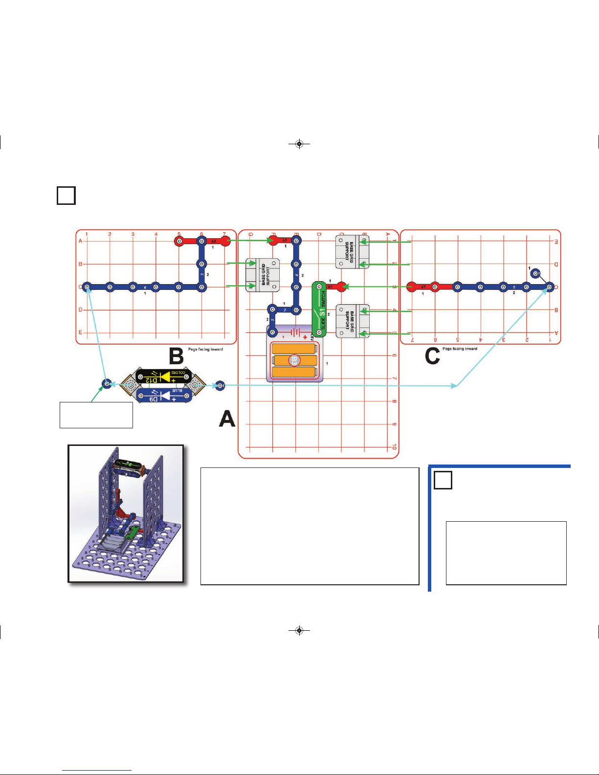
Project 40 Box Cover Circuit
This circuit is shown on the
cover of the Snap Circuits
®
3D
Illumination box and manual.
Use that picture to help with
building it.
Note: Go to: www.snapcircuits.net/sc3dmeg
for interactive
3D pictures to help with building the 3D circuits.
SC-3DMEG_Manual.qxp_SC-3Di_Manual_060816 6/19/17 7:30 PM Page 32
Page 33

-32-
Assembly (adult supervision highly recommended):
1. Place base grid supports on base grid A.
2. Mount parts on grids B & C (for jumper wires, leave one end
unconnected), and install in base grid supports in grid A. The pegs
should be facing inward. Do not use the double-sided grid.
3. Place remaining parts on grid A, and finish connecting the jumper
wires.
4. Mount grids D & E at the angles shown and with pegs facing down,
on top of grids
B & C using six stabilizers, attaching the two angled snap wires (V2) and
two 90 degree vertical snap wires (V1) as you do it. Note that grid D is
the double-sided grid. Adjust the positions of the stabilizers as needed.
5. Add the remaining parts on grids D & E. Note that the blinking red LED
is on the male-male snaps on grid D, facing up.
6. Tie string to the magnet and hang it from the ceiling so that it hangs
level near the reed switch (S9). When the circuit is on, adjust the string
so spinning the magnet with your finger lights the blue LED (D9), then
secure the string with tape.
Turn on the slide switch (S1). The clear motor (M4) spins a ceiling fan,
the lamp (L4) lights, the blink red LED (D11) lights, the color LED (D12)
lights up the fiber optic festive tree, the orange motor (M9) spins the
mirror ball, and the melody IC (U32) makes sound. Gently spin the
magnet with your finger; the compass needle should follow it. Push the
magnet near the reed switch (S9) and the blue LED (D9) lights.
SC-3DMEG_Manual.qxp_SC-3Di_Manual_060816 6/19/17 7:30 PM Page 33
Page 34

Project 41 Disco Effects
Assembly (adult supervision recommended):
1. Place base grid supports on base grid A.
2. Place parts on base grids B, & C, and install into base grid supports on grid A. The
pegs should be facing inward.
3. Place the remaining parts on grid A.
4. Place the mirror ball on the orange motor (M9).
Turn on the slide switch (S1) to spin the mirror ball and light the LEDs (D9 and D12).
Take the circuit into a dark room for best effects.
-33-
SC-3DMEG_Manual.qxp_SC-3Di_Manual_060816 6/19/17 7:30 PM Page 34
Page 35

Project 42
Disco Effects (II)
Assembly (adult supervision recommended):
1. Place base grid supports on base grid A.
2. Place parts on base grids B, & D, and install into base grid
supports on grid A. The pegs should be facing inward.
3. Mount grid C on top of grids B & D using 4 stabilizers,
attaching the 2 vertical snap wires (V1) as you do it.
\
4. Place the remaining parts on grids A & C. Note that grid C is
upside down, so place the parts on it carefully. The mirror ball
is placed on the orange motor (M9).
Turn on the slide switch (S1) to spin the mirror ball and light the
LEDs (D9, D11, and D12). Take the circuit into a dark room for
best effects.
-34-
SC-3DMEG_Manual.qxp_SC-3Di_Manual_060816 6/19/17 7:30 PM Page 35
Page 36

-35-
Project 43
Overhead Lights
SC-3DMEG_Manual.qxp_SC-3Di_Manual_060816 6/19/17 7:30 PM Page 36
Page 37

-36-
Use the preceding circuit, but carefully replace the blink red LED
(D11) with the clear motor (M4) with the green fan, or replace any of
the LEDs (D9, D11, or D12) with the lamp (L4) or the melody IC
(U32, “+” on right).
Project 44
Overhead Lights & More
Assembly (adult supervision recommended):
1. Place base grid supports on base grid A.
2. Place parts on base grids B, & D, and install into base grid supports
on grid A. The pegs should be facing inward.
3. Mount grid C on top of grids B & D using 4 stabilizers, attaching the 2
vertical snap wires (V1) as you do it.
4. Place the remaining parts on grids A & C.
Turn on the slide switch (S1) to light the three LEDs.
SC-3DMEG_Manual.qxp_SC-3Di_Manual_060816 6/19/17 7:31 PM Page 37
Page 38

-37-
Project 45
Lifting
Assembly (adult supervision recommended):
1. Place base grid supports on base grid A.
2. Tie one end of a piece of string to the hole
in the gear insert, and place the gear insert
on the orange motor (M9). Insert the screw
into the orange motor shaft but do not
screw it in very far.
3. Place parts on base grid B and install into
base grid supports on grid A. Grid B
should be the two-sided grid.
4. Place the remaining parts on grid A and
connect the red and black jumper wires.
Tie a light object (such as an extra base grid support) to the other end of the string. Turn on
the slide switch (S1). The orange motor spins; pull the string away from the gear insert a
little so that the string winds around the screw, slowly raising your object. You can place the
circuit near the edge of a table to lift the object farther. Turn off the slide switch before the
lifted object reaches the slow motor and interferes with it.
Swap the connections of one end of the red and black jumper wires to make the orange
motor turn in the opposite direction and lower the object.
Don’t lift a heavy object or the orange motor may fall off the base grid.
SC-3DMEG_Manual.qxp_SC-3Di_Manual_060816 6/19/17 7:31 PM Page 38
Page 39

Project 46
Windmill
Assembly:
1. Place base grid supports on base grid B.
2. Place parts on grid A, and install into base
grid supports on grid B.
3. Install remaining parts on grid B.
Blow on the fan to simulate a strong wind. If
you blow hard enough then the color2 LED
(D12) will light.
Here the clear motor (M4) is used as a
generator, using mechanical motion to
produce electricity. Commercial windmills
have more efficient motors, better fan
blade shapes, and low friction between
their components, so they can produce
electricity even in light winds.
Modify the preceding circuit to be this one.
Blow on the fan to simulate wind. If you blow
hard enough then the color2 LED (D12)
lights. See if it is easier to light the LED than
with the previous circuit.
Project 47 Mini Windmill
This circuit improves the
air flow by removing the
base grid from behind the
fan, but may not be as
stable.
-38-
SC-3DMEG_Manual.qxp_SC-3Di_Manual_060816 6/19/17 7:31 PM Page 39
Page 40

Project 48 Tall Angled Roof House
-39-
SC-3DMEG_Manual.qxp_SC-3Di_Manual_060816 6/19/17 7:31 PM Page 40
Page 41

Assembly (adult supervision highly recommended):
1. Place base grid supports on base grid A.
2. Place parts on base grids B & C, and install into base grid supports on
grid A. The pegs should be facing inward. Do not use the double-sided
grid.
3. Place remaining parts on grid A.
4. Mount grids D & E, at the angles shown and with pegs facing down,
on top of grids B & C using 6 stabilizers, and attaching the 45 degree
vertical snap wires (V2) from grids B & C and adding one 90 degree
vertical snap wire (V1) as you do it. Note that grid D should be the
double-sided grid. Adjust the positions of the stabilizers as needed.
5. Add the remaining parts on grids D & E.
Turn on the slide switch (S1) to light the lamp (L4).
Underside
view
-40-
SC-3DMEG_Manual.qxp_SC-3Di_Manual_060816 6/19/17 7:31 PM Page 41
Page 42

Use the preceding circuit, but carefully replace the lamp (L4) with the melody IC (U32), clear
motor (M4, with green fan), or one of the LEDs (D9, D11, or D12). The “+” side should be to
the left.
Project 49
Tall Angled Rood House Variants
Use the preceding circuit, but
carefully change the parts on
grid D to match the circuit
shown here.
Project 50
Enhanced Tall Angled Roof House
Underside
view
Use the preceding circuit, but carefully rearrange any of the lights, or replace them
with the melody IC (U32) or clear motor (M4, with green fan). “+” side should always
be on the left. Exception: do not replace the color2 LED (D12) with the clear motor,
because vibration could cause the Motor to come loose and fall.
Project 51
Enhanced Tall Angled Roof
House Variants
-41-
SC-3DMEG_Manual.qxp_SC-3Di_Manual_060816 6/19/17 7:31 PM Page 42
Page 43

-42-
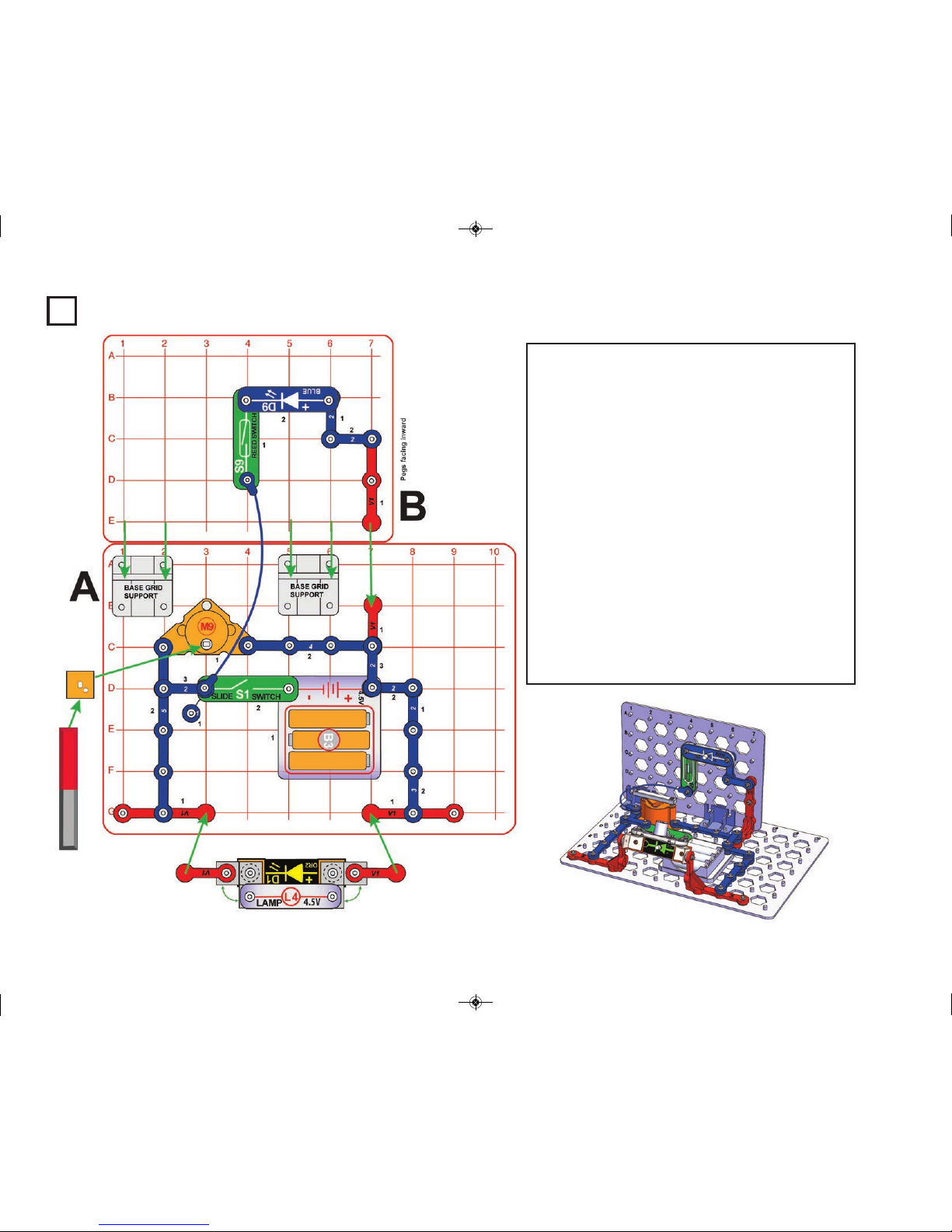
Project 52 House with Doorbell
Assembly:
1. Place parts on grid B, including the base grid support, 90 degree vertical
snap wires (V1), and press switch (S2). Note that grid B is the two-sided
grid, and the press switch is on the reverse side. Install grid B on grid A.
2. Place remaining parts on grid A.
3. Install grids C, D, & E into base grid supports on grid A, and secure with
4 stabilizers.
Push the press switch to ring the doorbell. It sounds best if you press it for
a few seconds.
SC-3DMEG_Manual.qxp_SC-3Di_Manual_060816 6/19/17 7:31 PM Page 43
Page 44

-43-
Project 53 Festive House with Roof Lights
SC-3DMEG_Manual.qxp_SC-3Di_Manual_060816 6/19/17 7:31 PM Page 44
Page 45

-44-
Assembly (adult supervision highly recommended):
1. Place base grid supports on base grid A.
2. Mount parts on grids B and install in base grid supports in grid A. The
pegs should be facing inward. Do not use the double-sided grid.
3. Place remaining parts on grid A.
4. Mount grids D & E at the angles shown and with pegs facing down, on
top of grids
B & C using six stabilizers, attaching the two angled snap wires (V2) and
two 90 degree vertical snap wires (V1) as you do it. Note that grid D is the
double-sided grid. Adjust the positions of the stabilizers as needed.
5. Add the remaining parts on grid D.
Turn on the slide switch (S1). The clear motor (M4) spins a ceiling fan, the
melody IC (U32) plays a tune, and the lamp (L4) lights. This circuit looks
best in a dark room.
SC-3DMEG_Manual.qxp_SC-3Di_Manual_060816 6/19/17 7:31 PM Page 45
Page 46

-45-
Project 54
Chandelier Circuit
1
SC-3DMEG_Manual.qxp_SC-3Di_Manual_060816 6/19/17 7:31 PM Page 46
Page 47

-46-
Assembly:
1. Place base grid supports on base grid A.
2. Place parts base grid B, then install grids B & D into base grid
supports on grid A. The pegs on grid B must be pointed inward. Any
of the mini grids can be the two-sided grid.
3. Attach the large gear to the gear insert, place it on the orange motor
(M9) and secure it with the screw.
4. Place the orange motor on grid C, then mount grid C on top of grids
B & D using 4 stabilizers.
5. Place the remaining parts on grids A & C.
Turn on the slide switch (S1) to spin the large gear, light the lamp (L4),
and play a melody.
Use the preceding circuit, but remove the melody IC (U32),
or replace it with one of the LEDs (D9, D11, or D12).
Project 55
Quiet Chandelier Circuit
SC-3DMEG_Manual.qxp_SC-3Di_Manual_060816 6/19/17 7:31 PM Page 47
Page 48

-47-
Project 56 Indoor & Outdoor Lights
SC-3DMEG_Manual.qxp_SC-3Di_Manual_060816 6/19/17 7:31 PM Page 48
Page 49

-48-
Assembly:
1. Place base grid supports on base grid A.
2. Place parts base grids B & C, then install grids B, C, & D into base
grid supports on grid A. The pegs on grids C must be pointed inward.
Grid B must be the two-sided grid.
3. Mount grid E on top of grids B & D using 4 stabilizers.
4. Place the remaining parts on grid A.
Turn on the slide switch (S1) to light the LEDs (D9, D11, & D12) and
lamp (L4), and play a melody.
Use the preceding circuit, but remove the melody IC
(U32), or replace it with the clear motor (M4) and wind
fan. You can also re-arrange the lights, melody IC, or
clear motor.
Project 57
Indoor &
Outdoor
SC-3DMEG_Manual.qxp_SC-3Di_Manual_060816 6/19/17 7:31 PM Page 49
Page 50

-49-
Project 58 Disco Lights
Build the circuit as shown; it has the blue LED (D9) and
color2 LED (D12) each mounted on two vertical snap
wires (V1). Place the mirror ball on the orange motor (M9).
Turn on the slide switch (S1. Place the circuit in a dark
room, so that light from the blue and color2 LEDs reflects
off the mirror ball to the walls and ceiling. The press and
reed switches (S2 & S9) are used only for mechanical
support, and not electrically connected.
Project 59
Angled Disco Projector
Build the circuit as shown; it has the blue LED (D9) mounted on two 45
degree vertical snap wires (V2). Place the mirror ball on the orange
motor (M9).
Turn on the slide switch (S1) and place the circuit in a dark room, so
that light from the blue LED reflects off the mirror ball to a nearby wall
and ceiling.
SC-3DMEG_Manual.qxp_SC-3Di_Manual_060816 6/19/17 7:31 PM Page 50
Page 51

Project 60
Both Sides Lights
Assembly:
1. Place base grid supports on base grid A.
2. Place parts base grids B, then install grid
B into base grid supports on grid Grid B
must be the two-sided grid.
3. Place the remaining parts on grid A.
Turn on the slide switch (S1) to light the
LEDs (D9, D11, & D12) and lamp (L4), and
play a melody.
Project 61
Quiet Both Sides Lights
Use the preceding circuit, but remove the
melody IC (U32). You can also re-arrange
the lights.
Project 62
Spinning Magnet
Build the circuit, place the gear
insert on the orange motor (M9),
then lay the magnet so it is
centered on the gear insert. Turn
on the slide switch (S1). The
orange motor slowly spins the
magnet, activating the blue LED
(D9) as the magnet passes over
the reed switch (S9).
-50-
SC-3DMEG_Manual.qxp_SC-3Di_Manual_060816 6/19/17 7:32 PM Page 51
Page 52

Project 63 Disco Spotlight
Assembly:
1. Place base grid supports on base
grid A.
2. Place parts base grids B, then
install grid B into base grid
supports on grid A. Note that the
blue LED (D9) is mounted on the
45 degree vertical snap wires
(V2) so it can shine over grid A.
3. Place the remaining parts on grid
A. Mount the mirror ball on the
orange motor (M9).
Turn on the slide switch (S1). The
orange motor spins the mirror ball,
and the blue LED shines on it. Place
the circuit in a dark room to see
disco lights on the walls and ceiling.
The reed switch is used here only for
mechanical support, so do not
activate it.
Project 64
Spotlight
Use the preceding circuit, but replace the
blue LED(D9) with the color2 LED (D12),
blink red LED (D11), or the lamp (L4). You
can also replace the orange motor (M9) and
mirror ball with the clear motor (M4) and
wind fan.
Project 65 Spin the Magnet
Build the circuit, with the wind fan
mounted on the clear motor (M4).
Lay the magnet on the fan and
slowly spin the fan with your
finger, keeping the magnet on the
fan. The blue LED (D9) should
turn on and off as the magnet
moves over the reed switch (S9).
-51-
SC-3DMEG_Manual.qxp_SC-3Di_Manual_060816 6/19/17 7:32 PM Page 52
Page 53

Project 66
2-Speed Mirror Ball
Build the circuit,
placing the mirror
ball on the orange
motor (M9) and
the wind fan on
the clear motor
(M4). Turn on the
slide switch (S1);
both the mirror
ball and the fan
spin. Push the
press switch (S2)
to speed up the
mirror ball and
shut off the fan.
Use the preceding circuit but swap the locations of the
orange and clear motors, to match the circuit shown
here. Turn on the slide switch (S1); both the mirror ball
and the fan spin. Push the press switch (S2) to speed
up the fan and stop the mirror ball.
Project 67
2-Speed Fan
Project 68
Musical Mirror
Ball
Build the circuit, placing
the mirror ball on the
orange motor (M9). Turn
on the slide switch (S1). A
melody plays and the
mirror ball spins. The
speed of the mirror ball
varies as the melody
changes. The sound may
be abnormal, especially if
your batteries are weak.
Project 69
Musical
Fan
Use the preceding circuit, but replace the orange
motor (M9) and mirror ball with the clear motor (M4)
and wind fan. The fan speed may vary a little as the
melody changes, and the sound may be abnormal.
-52-
The clear motor briefly stops
or reduces speed as the
melody changes, but may
be spinning too fast for the
effects to be easily seen.
SC-3DMEG_Manual.qxp_SC-3Di_Manual_060816 6/19/17 7:32 PM Page 53
Page 54

Project 70
Tree House
-53-
SC-3DMEG_Manual.qxp_SC-3Di_Manual_060816 6/19/17 7:32 PM Page 54
Page 55

Assembly (adult supervision recommended):
1. Place base grid supports on base grid A.
2. Place parts base grids B & D, then install grids B, C, & D into base grid supports
on grid A. The pegs must be pointed inward. Do not use the two-sided grid.
3. Place the blue & color2 LEDs (D9 & D12) on grid E, then mount grid E on top
of grids B & D using 4 stabilizers, attaching the two 90 degree vertical snap
wires (V1) as you do it. Grid E must be the two-sided grid. Place the remaining
parts on grid E.
4. Place the remaining parts on grid A .Mount the mirror ball on the orange motor (M9),
and mount the fiber optic festive tree on the color2 LED using the mounting base.
Turn on the slide switch (S1). The blue LED shines on the spinning mirror ball,
the color2 LED lights up the festive tree, and the melody IC (U32) plays music.
For best effects place the circuit in a dark room.
Use the preceding circuit, but replace the blue LED (D9)
with the lamp (L4).
Project 71 Brighter Tree House
Use the project 70 circuit, but swap the locations of the blue
LED (D9) and color2 LED (D12).
Project 72
Blue Tree House
-54-
SC-3DMEG_Manual.qxp_SC-3Di_Manual_060816 6/19/17 7:32 PM Page 55
Page 56

Use any of the preceding
6 circuits, but remove the
melody IC (U32).
Project 76
Use the project 70 circuit, but add two 45
degree vertical snap wires (V2) beneath the
color2 LED (D12). Then add the reed switch
(S9) and lamp, so that the lamp will shine
towards the festive tree. The reed switch is
only used here for mechanical support, so
do not use the magnet to activate it.
Project 73
Use any of the preceding
5 circuits but replace the
fiber optic festive tree
with the egg.
Project 75
Egg House
Use the preceding 4
circuits, but replace the
lamp (L4), blue LED
(D9), or color2 LED
(D12) with the blink red
LED (D11).
Project 74
Blinking Tree
House
Use any of the preceding 7 circuits, but remove the orange
motor (M9) and mirror ball, move the melody IC (U32) to where
the orange motor was, then place the clear motor (M4) and
wind fan where the melody IC was.
Project 77
Tree House with Fan
Silent Tree
House
-55-
Highlighted Tree House
SC-3DMEG_Manual.qxp_SC-3Di_Manual_060816 6/19/17 7:32 PM Page 56
Page 57

Project 78 Manual Rotation Vertical Lights
Assembly (adult supervision recommended):
1. Place base grid supports on base grid A.
2. Place parts on grid B, and install into base grid support on grid A. The pegs should be facing inward.
3. Mount the blue & color2 and LEDs (D9 & D12) to the 3D snaps, and attach two 1-snap wires on
opposite sides, as shown.
4. Place the remaining parts on grid A.
5. Mount the LED assembly from step 3 between the vertical snap wire that hangs upside down from
grid B and the 3-snap wire on grid A, as shown. The “+” side of the LEDs should be up.
Turn on the slide switch (S1). The color2 and blue LEDs should light; rotate them to any desired
position.
Use the preceding circuit, but
replace any of the LEDs (D9 &
D12) with the blink red LED
(D11), the lamp (L4), or the
melody IC (U32).
Manual Rotation
Vertical Lights
Variants
Project 80 Stay with the Magnet
Build the circuit, mounting the gear insert
on the orange motor (M9) and placing the
compass so it is centered on the gear
insert. Turn on the slide switch (S1) and
hold the magnet near the side of the
compass. The compass needle should
always point towards the magnet, even as
the motor rotates the compass. Move the
magnet around until you find a position
where this works well. Next, move the
magnet far away. The compass needle
should point north, and continue pointing
north as the compass itself is rotated by the
motor.
Project 79
-56-
SC-3DMEG_Manual.qxp_SC-3Di_Manual_060816 6/19/17 7:32 PM Page 57
Page 58

Project 81 Ceiling Disco Ball
-57-
SC-3DMEG_Manual.qxp_SC-3Di_Manual_060816 6/19/17 7:32 PM Page 58
Page 59

Assembly (adult supervision recommended):
1. Place base grid supports on base grid A.
2. Place parts on base grids B & C, and then install grids B & C into base
grid supports on grid A. The pegs must be pointed inward. Do not use
the two-sided grid.
3. Place the parts on grid A.
4. Mount the mirror ball (MB) on the orange motor (M9). Place the motor
and color Led (D12) on the grid D, then connect the both parts use two
2-snaps.
5. Mount grid D on top of grids B & C using 4 stabilizers, attaching the two
vertical snap wires (V1) as you do it.
6. Place the remaining parts on grid D.
Turn on the slide switch (S1). The blue LED and lamp shines on the
spinning mirror ball and the melody IC (U32) plays music. For best effects
place the circuit in a dark room.
-58-
SC-3DMEG_Manual.qxp_SC-3Di_Manual_060816 6/19/17 7:32 PM Page 59
Page 60

Project 82
Rotating Field
Project 83 Flash and Sound
Turn on the slide switch (S1). The
circuit makes strange sounds and
lights. The sound is not very loud.
You can replace either LED (D9 or
D12) with the blink red LED (D11).
-59-
Build the circuit, mounting the gear insert
and the large gear on the orange motor (M9).
Place the magnet in the center of the gear.
Turn the slide switch (S1) on and the gear
starts to rotate. When one end of the magnet
faces the reed switch (S9), the fan spins
and blue LED flashes. The compass needle
will also rotate as it follows the rotating the
magnetic field.
SC-3DMEG_Manual.qxp_SC-3Di_Manual_060816 6/19/17 7:32 PM Page 60
Page 61

Project 84 Lifter
Assembly :
1. Place base grid supports on base grid A.
2. Place parts on both sides of the double sided grid B, then install grid B into base grid supports on grid A.
3. Place remaining parts on grid A. Mount the gear insert and the large gear on the orange motor (M9). Place the
magnet in the center of the gear.
4. Mount the Illusion card holder onto the clear motor (M4) and insert string into the slots as shown.
5. Wind the string around the shaft several times to get it started.
6. Tie the other end of the string to a 45 degree vertical snap wire (V2) or base grid support.
7. Place circuit so the motor is over the edge of the table as shown.
8. Place the 45 degree vertical snap wire on the floor and wind the string around the shaft so it is straight.
Turn on the slide switch (S1). The gear starts turning as the red and blue LEDs (D11 & D9) light. When the magnet
passes the reed switch (S9) the 45 degree vertical snap wire (or base grid support) rises then falls and the color2
LED (D12) flashes. Push the press switch (S2) if the orange motor does not start.
If the base grid support does not have enough weight to pull the string down, then tie the string to something heavier.
When the motor spins
backwards it generates a
voltage which lights the
color LED.
-60-
SC-3DMEG_Manual.qxp_SC-3Di_Manual_060816 6/19/17 7:32 PM Page 61
Page 62

Use Project 84 circuit, but remove the
string and 45 degree vertical snap wire
(V2). Replace with the Illusion card
holder with the fan. Turn on the slide
switch (S1); when the magnet passes
the reed switch (S9) the fan spins and
then turns off. The color2 LED (D12) will
not flash since the motor does not turn
backwards.
Project 86
Magnet Fan
Use the preceding circuit, but place the
blue jumper wire across the red LED
(D11). Turn on the slide switch (S1); the
fan spins more often since the gear
spins faster.
You can also swap the blue & red LEDs
(D9 & D11) to make the lights different.
Project 87
Fast Magnet Fan
Project 88 45° LEDs
Place all the parts on the base grid,
then install the blue LED (D9) and
color LED (D12) on the 45 degree
snap wires (V2). Turn on the slide
switch (S1); both LEDs should light.
Project 85
Fast Lifter
Place a blue jumper wire across the
red LED (D11). Turn on the slide
switch (S1); the 4
5 degree vertical
snap wire
(V2) rises and falls more
often since the gear spins faster.
You can also swap the blue & red
LEDs (D9 & D11) to make the lights
different.
Project 89 Pivot LED Bar
-61-
Place the parts on the base grid, then
assemble the parts on the vertical snap
wires (V1).
Push the press switch (S2) on; the LEDs and
lamp turn on. The LEDs pivots around the
top snap of vertical snap wires; move the
LEDs to different positions,
SC-3DMEG_Manual.qxp_SC-3Di_Manual_060816 6/19/17 7:32 PM Page 62
Page 63

Project 90 Side Ways
Place all the parts on the base
grid, then the parts on the four
vertical snap wires. Turn on the
slide switch (S1); the lights turn
on, the fan spins, and the music
plays.
Project 91 Side Ways 2
-62-
Use the preceding circuit, but attach a 3D snap
on the back of the two vertical snap wires (V1)
connected to the clear motor (M4) and lamp
(L4). Attach the orange motor (M9) across the
two 3D snaps as shown. Mount the gear insert
and large gear on the orange motor.
Turn on the slide switch (S1). The lights turn on,
music plays, the fan spins, and the gear rotates.
SC-3DMEG_Manual.qxp_SC-3Di_Manual_060816 6/19/17 7:32 PM Page 63
Page 64

Project 92
Swing LEDs
Place the circuit on a white page and
rotate so the LEDs are facing down.
Turn on the switch; a color pattern
shines on the page. Change the
image size by rotating the LEDs
upwards.
Project 94 Follow the Field
Project 93
Swing LEDs ?
Build the circuit as shown,
mounting the gear insert and the
small gear on the orange motor
(M9). Place the magnet in the
center of the gear.
Mount the compass on the 3D
snap, making sure it is level. Turn
on the slide switch (S1). The gear
and compass needle should be
turning in opposite directions.
You can use a compass to trace
out the magnetic field lines of a
bar magnet. The needle of a
compass is itself a permanent
magnet and the north indicator
of the compass is a magnetic
north pole.
A magnetic north pole will
attract the south pole of another
magnet, and repel a north pole.
Place all the parts on the base
grid, then assemble the LEDs on
the vertical snap wires (V1).
Turn on the slide switch (S1) and
all the LEDs light. Adjust the
LEDs to different angles.
-63-
SC-3DMEG_Manual.qxp_SC-3Di_Manual_060816 6/19/17 7:32 PM Page 64
Page 65

Project 95 Rocking Switch
Build the circuit, then place the magnet across the base grid
supports as shown. Turn on the slide switch (S1) and the red
LED (D11) starts blinking. Slowly rotate the reed switch (S9)
towards the magnet. When the reed switch is close enough to
the magnet the switch closes, the lamp (L4) lights, and the LED
turns off.
The magnetic field holding the switch closed decreases as the
switch moves past the magnet. The switch opens again, lamp
turns off, and the LED blinks.
Project 96
Disco Ball Switch
Use the preceding circuit. Place the orange
motor (M9) across base grid locations F4 &
F6 on level 1. Connect the motor across the
lamp using two blue jumper wires (J4). Mount
the mirror ball on the motor and move the
reed switch (S9) away from the magnet. Turn
on the slide switch (S1); when the reed switch
is on, the disco ball rotates and the lamp
lights.
Project 97
Rocking Switch LEDsDisco Ball Melody
Use project 95. Place the color2 LED (D12)
and the blue LED (D9) across base grid
locations F4 & F6 and G4 & G6 on level 1.
Connect the LEDs using 2-snaps across F4
& G4 and F6 & G6 on level 2. Place two blue
jumper wires (J4) across E4 & F4 and E6 &
F6. Now, all lights turn on when the reed
switch is closed.
Project 98
Use the preceding circuit, but replace the
lamp (L4) with the melody IC (U32, + on
left). Turn on the slide switch (S1); when
the reed switch (S9) is closed the disco
ball rotates and the melody IC sounds.
-64-
Reed switches are used in
security systems to indicate if a
door or window is opened.
Note: If the LED
assembly fit seems
loose add a 1-snap
wire between one of
the 3D snaps and a V1.
SC-3DMEG_Manual.qxp_SC-3Di_Manual_060816 6/19/17 7:32 PM Page 65
Page 66

Project 99 Speed Change
Build the circuit as shown; mounting the gear insert and
the small gear on the orange motor (M9). Place the
magnet in the center of the gear.
Turn the slide switch (S1) on; the gear rotates, and the
blue LED (D9) lights as a melody plays. Rotate reed
switch to different positions.
When the end of the magnet is towards the reed switch
(S9), the reed switch turns on. The orange motor slows,
the red LED (D11) starts blinking, and the blue LED and
melody IC (U32) turn off until the magnet end passes.
Build the circuit shown. Blow on the
fan so the
clear motor (M4)
generates
enough voltage to light the blink red
LED (D11).
Now place the color2 LED (D12)
across base grid locations B4-D4 (+ at
D4). Blow on the fan again to light
both LEDs.
Project 100
Fan Power
Use the preceding circuit, but
place the blue LED (D9)
across base grid locations B4
& D4 and the melody IC
(U32) across B5 & D5 (+ at
bottom). The fan really needs
to spin very fast for all the
LEDs to light and the melody
IC to make sound.
Project 101
Fan Power 2
-65-
Note: If the LED
assembly fit seems
loose add a 1-snap
wire between one of
the 3D snaps and a V1.
SC-3DMEG_Manual.qxp_SC-3Di_Manual_060816 6/19/17 7:32 PM Page 66
Page 67

Project 102 Door Bell
Build the circuit; mounting the gear insert and the
small gear on the orange motor (M9) as shown.
Place the magnet on the gear. Turn the slide switch
(S1) on; the gear rotates and the blue LED (D9)
lights. When the magnet moves near the reed
switch (S9), the melody IC (U32), color2 LED
(D12), and lamp (L4) turn on and off twice. The
melody IC sounds like a door bell.
Project 104
Fan Speed
Use the project 102 circuit, but replace
the lamp (L4) with the clear motor (M4)
and fan. Turn the slide switch (S1) on;
the blue lights and the fan spins slowly.
When the reed switch closes U32, D12
and L4 turn on and the fan speeds up.
Project 105
Disco Ball Switch
Use the project 102 circuit, but replace the
melody IC (U32) with the blink red LED
(D11) and remove the lamp (L4). Place the
egg on the blink red LED and the fiber optic
festive tree on the color2 LED (D12) using
the mounting base. Turn on the slide
switch; now the egg and tree light together.
Project 103
Door Bell Lights
Use the preceding circuit, but place one
of the LED attachments (fiber optic
festive tree or egg) on the color2 LED
(D12), and dim the room lights. The fiber
optic festive tree must be used with its
mounting base.
-66-
Note: If the LED
assembly fit seems
loose add a 1-snap
wire between one of
the 3D snaps and a V1.
SC-3DMEG_Manual.qxp_SC-3Di_Manual_060816 6/19/17 7:32 PM Page 67
Page 68

Project 106
Fan Speed
Build the circuit as shown, mounting the gear insert and
the large gear on the orange motor (M9). Place the magnet
in the center of the gear.
Turn the switch on, the gear slowly rotates, the blue LED
lights and the fan spins. When the end of the magnet is
towards the reed switch the orange motor (M8) speeds up,
clear motor (M4) slows down and the blinking LED (D11)
gets brighter.
Project 107
If you have any extra
magnets compare
their strenth using
this project. See
which one can be
held farthest away
from the reed switch.
Project 108
-67-
Use the preceding circuit, remove
the magnet and hold it next to the
reed switch. The fan and blue LED
turn off, geared motor speeds up and
LED D11 is blinking. See how close
the magnet must be to the reed
switch.
Manual Fan Speed
Use the preceding circuit, remove the two snap
on B6 & C6. Turn the switch on, only LED D11
blinking and the fan spins slowly. Stop the fan by
placing the magnet next to the reed switch.
Fan Speed 2
SC-3DMEG_Manual.qxp_SC-3Di_Manual_060816 6/19/17 7:33 PM Page 68
Page 69

-68-
Project 109
Mirror Ball Speed Control
Build the circuit and turn on the
slide switch (S1). The mirror
ball spins and three LEDs light.
Push the press switch (S2) to
make the mirror ball spin faster.
Use the preceding circuit, but remove any one or
two of the LEDs (D9, D11, and D12).
Next, add the lamp (L4) in place of one of the
removed LEDs. Compare the mirror ball speed.
Project 110
Mirror Ball Speed
Control (II)
Use the project 109 circuit,
but replace one of the LEDs
with the clear motor (M4)
and fan. Compare the mirror
ball speed.
Next, remove another of the
LEDs and compare the
mirror ball speed.
Project 111
Mirror Ball Speed
Control (III)
Use the project 109 and 110
circuits but replace the
orange motor (M9) and
mirror ball with the clear
motor (M4) and fan.
Compare the fan speed as
you push the press switch
(S2) or remove one or two
LEDs.
Project 112
Fan Speed
Control
Use the project 109 and 110
circuits but replace the
orange motor (M9) and
mirror ball with the clear
motor (M4) and illusion card
holder, with one of the
illusion cards in it. Compare
the image on the spinning
illusion card as you vary the
spin speed.
If the illusion card comes out
at high speed then insert a
small piece of paper into the
cardholder with the illusion
card to make it fit more
snugly.
Project 113
Illusion Card
Speed Control
The lamp has low
resistance, so adding it
will be similar to pushing
the press switch (S2).
All the electricity flowing
through the orange motor
(M9) splits up between the
three LEDs. The press switch
speeds up the orange motor
by bypassing the LEDs.
SC-3DMEG_Manual.qxp_SC-3Di_Manual_060816 6/19/17 7:33 PM Page 69
Page 70

Project 114
Generator
Build the circuit as shown; then mount the illusion card holder on
the motor shaft. Wind the string through the mirror holder and then
around the motor shaft about 10 times. Holding the base with one
hand pull the string; the blue LED (D9) lights briefly. Spinning the
motor generates enough voltage to light the LED. Push the press
switch (S2) to rewind the string and try lighting the LED again.
Now move the end of the red jumper wire from base grid location
B3 to D4, to add the blink red LED (D11) to the circuit. When you
pull the string now, LEDs D9 and D11 light briefly.
Project 115
Generator 2
Use the preceding circuit, but place the color2 LED
(D12) across base grid locations B5 & D5 (+ side to D5),
and add a 2-snap across base grid locations D4 & D5.
Move the end of the red jumper wire from base grid
location B3 to B5. Pull the string and all three LEDs
should light.
-69-
Project 116
Build the circuit as shown, leaving the ends of the red &
black jumper wires unconnected for now. Turn on the slide
switch (S1); the blue LED (D9) should be off.
Place the loose ends of the red & black jumper wires into
a cup of water (but not distilled water), without them
touching each other. The blue LED should be on now,
because water conducts electricity, completing this circuit.
Try dissolving some salt in the water or using different
liquids, and see how the LED brightness changes.
Don’t drink any liquids used here.
Use the preceding circuit, but
instead of placing the red & black
jumper wires in water, touch the
metal part of each with your
fingers, using your body to
complete the circuit. Wet your
fingers to get better electrical
contact. The blue LED (D9)
should be on, but brightness may
vary.
Project 117
You Complete the Circuit
Water Completes the Circuit
The clear motor (M4) can also be used to generate electricity,
all that you have to do is turn the shaft. But you have to turn
the shaft very fast to generate enough electricity to do much.
SC-3DMEG_Manual.qxp_SC-3Di_Manual_060816 6/19/17 7:33 PM Page 70
Page 71

-70-
Project 118
Arrow LEDs
Place all the parts on the base grid then
assemble the parts on and around the two 45
degree vertical snap wires (V2) Turn the slide
switch (S1); the LEDs light and form a arrow
shape. You can attach the egg to one of the
LEDs.
Project 119 Arrow Melody
Use the preceding circuit, add sound by placing the
melody IC (U32) across base grid locations C3-E3 on
level 3 (+ towards battery holder). Turn on the slide
switch(S1), the LEDs light and as the melody plays.
SC-3DMEG_Manual.qxp_SC-3Di_Manual_060816 6/19/17 7:33 PM Page 71
Page 72

Project 120 Light Stairs
Place all the parts on the
base grid, then assemble the
parts on the two 90 degree
vertical snap wires (V1).
Position the LEDs to the right
as shown. Turn on the slide
switch (S1); all the lights turn
on and a melody plays.
Adjust the light assembly to
different positions.
Project 121 Light Stairs 2
Use the preceding
circuit, but replace
the 2-snap wires and
1-snap wires under
LEDs D11 and D12
with two 45 degree
vertical snap wires.
Turn on the slide
switch (S1) and adjust
the light assembly to
different positions.
-71-
SC-3DMEG_Manual.qxp_SC-3Di_Manual_060816 6/19/17 7:33 PM Page 72
Page 73

Project 122
Egg Head
Place all the parts on the base grid then assemble the parts on the two 90 degree
vertical snap wires (V1). Install the egg on the color2 LED (D12).
Turn on the slide switch (S1). The LEDs and lamp all light as the egg changes colors.
Place the parts on the base grid, then mount the 3-snap wires and lights on the 90 degree
vertical snap wires (V1), then add the 3D snaps and orange motor (M9), then add the 45
degree vertical snap wires (V2), then place the mirror ball on the orange motor.
Turn the switch on, the robot’s head spins and his body light up.
Project 123 Robot
-72-
SC-3DMEG_Manual.qxp_SC-3Di_Manual_060816 6/19/17 7:33 PM Page 73
Page 74

Project 124
Plane
Place the parts on the base grid, then assemble the parts on the
four 90 degree vertical snap wires (V1).
Be sure to hold the “plane” so that the green fan does not touch
the base grid.
Turn the slide switch (S1) on; the plane’s prop spins with lights and
sound. Rotate the body to simulate flying up or down.
-73-
SC-3DMEG_Manual.qxp_SC-3Di_Manual_060816 6/19/17 7:33 PM Page 74
Page 75

Project 125
Mini Plane
Place the parts on the base grid then assemble the parts on the four
90 degree vertical snap wires (V1).
Be sure to hold the “plane” so that the green fan does not touch the
base grid.Turn the slide switch (S1) on; the mini plane is flying with a
flashing tail light. Rotate the body to simulating flying up or down. if
desired, place the egg LED attachment on the blue LED (D9).
Use the preceding circuit, but replace the blue LED (D9) with the melody
IC (U32) and replace the blink red LED (D11) with the lamp (L4). Turn
the switch on; the mini plane now has sound and a white light.
Project 126
Music Mini Plane
-74-
Note: If the LED
assembly fit seems
loose add a 1-snap
wire between one of
the 3D snaps and a V1.
SC-3DMEG_Manual.qxp_SC-3Di_Manual_060816 6/19/17 7:33 PM Page 75
Page 76

Project 127 Triple Series
Build the circuit as shown, leaving the press switch (S2) out of the circuit
for now. Turn on the slide switch (S1); most likely nothing will happen.
Now add the press switch between the points labeled A&B, B&C, or
C&D, and push it. Try it at all 3 locations.
Most likely the battery voltage (4.5V)
will not be strong enough to turn on
any of the LEDs when all are
connected together in series. Adding
the press switch (S2) bypasses one
of them, and should allow the
remaining ones to operate, though
probably not at their best.
Project 128
Triple Parallel
Build the circuit and turn on the slide switch (S1). All the LEDs are bright.
All the LEDs are all connected
in parallel, and have enough
voltage to perform at their best.
ABC
D
-75-
SC-3DMEG_Manual.qxp_SC-3Di_Manual_060816 6/19/17 7:33 PM Page 76
Page 77

-76-
Project 129
AND Circuit
Place the magnet next to the reed switch (S9)
to turn it on, push the press switch (S2), and
turn on the slide switch (S1) in different
combinations while seeing if the lamp (L4)
lights. Fill out this table with the results:
Project 130
OR Circuit
S9 S1 S2 L4
OFF OFF OFF
OFF OFF ON
OFF ON OFF
OFF ON ON
ON OFF OFF
ON OFF ON
ON ON OFF
ON ON ON
Place the magnet next to the reed switch (S9)
to turn it on, push the press switch (S2), and
turn on the slide switch (S1) in different
combinations while seeing if the lamp (L4)
lights. Fill out this table with the results:
S9 S1 S2 L4
OFF OFF OFF
OFF OFF ON
OFF ON OFF
OFF ON ON
ON OFF OFF
ON OFF ON
ON ON OFF
ON ON ON
If switch S9, switch S1, AND switch S2 are on then the lamp will be on. Engineers refer
to this
switching combination as an AND sub-circuit (short for “this AND that”).
Having to turn on several switches just to turn on a lamp seems simple but is very
important. The press switch could represent an on/off switch on an electric saw,
one of the slide switches could be a safety switch on the saw, and the reed switch
could be a fuse box in your basement. Safety is very important in electrical wiring.
if switch S9, switch S1 OR switch S2 is on then the lamp will
be on. Engineers refer to this
switching combination as an
OR sub-circuit (short for “this OR that”). The same type
of circuit is used throughout your home, such as having
several sensors controlling a security light.
SC-3DMEG_Manual.qxp_SC-3Di_Manual_060816 6/19/17 7:33 PM Page 77
Page 78

-77-
Project 131
Back EMF
Build the circuit as shown.
Push the press switch
(S2) for a few seconds;
the fan spins but the red
LED (D11) doesn’t light.
When you release the
switch, the red LED
flashes. Wait until the fan
stops before pushing S2
again. The red LED is not
bright so dim the room
lights to see it better.
Use the preceding circuit, but remove the
blue jumper wire across base grid
locations C2 & E2. Press the switch the fan
spins. Release the press switch and now
both LEDs light. The LEDs are not bright
so dim the room lights.
See if the circuit has enough power to light
all the LEDS by removing the blue jumper
wire across base grid locations A2 & C2.
Project 132
EMF 2
Project 133 Lamp & Fan Independent
Build the circuit as shown.
Depending on which of the
switches (S1 & S2) are on, you
can turn on either the lamp (L4),
the clear motor (M4), or both
together. The color2 LED (D12) is
connected across the battery, so
it’s always on.
When the switch is pressed, electricity flows from
the battery (+), through the clear motor (M4) and
press switch, then back to the negative side (-) of
the battery, but does not flow through the LED
since it is backwards.
Electric current produces a magnetic field in the
motor and when the press switch is released, the
magnetic field collapses and generates an EMF
in the electromagnet coil windings. The voltage
produced by a motor when it is spinning is called
its Back Electro-Motive-Force (Back EMF).
The voltage can only power the LED for a second.
SC-3DMEG_Manual.qxp_SC-3Di_Manual_060816 6/19/17 7:33 PM Page 78
Page 79

-78-
When you close (turn on) the slide switch (S1), both LEDs (D9 & D11) turn
on. Current flows from the batteries through the switch back to the battery
through the LEDs. Remove the red LED (D11) and notice that the blue LED
(D9) does not change in brightness. In a parallel circuit each part has its
own path to the battery so removing one LED does not affect the other one.
The voltage is the same across the LEDs, but not the current.
LEDs in Parallel
Build the circuit and close (turn on) the slide switch (S1). The LEDs (D9 &
D11) light.
Current flows from the batteries through the LEDs and back to the battery
through the switch. The closed (on) switch completes the circuit. In
electronics this is called a closed circuit. When the switch is open (off), the
current can no longer flow back to the battery, so the LEDs turn off. In
electronics this is called an open circuit. Engineers refer to switches being
open or closed because the switch symbol resembles an architect’s
symbol for a door.
Project 134 LEDs in Series
Project 135
Project 136
Cross Over
Project 137
Cross Over Tree
Use the preceding circuit, but
place the fiber optic festive tree
on the color2 LED (D12) using
the mounting base.
Place the parts on the base grid, then assemble the parts on the three 90 degree
vertical snap wires (V1). The LEDs are in parallel so when you turn the switch
on, all should light.
Change the circuit by switching the LEDs around or add sound by replacing the
color2 LED (D12) with the melody IC (U32).
SC-3DMEG_Manual.qxp_SC-3Di_Manual_060816 6/19/17 7:33 PM Page 79
Page 80

-79-
Project 138
Project 140
Green Dot
Place the parts on the base grid, then assemble the
parts on the two 45 degree vertical snap wires (V2).
Turn on the slide switch (S1); the LEDs light as the
melody IC (U32) makes a strange sound; the sound
may not be very loud. The blue LED (D9) next to the
motor (M4) creates a green line across the spinning
fan.
Remove the clear motor (M4). Now the sound is much
louder.
Lighted Cross
Project 139
Build this circuit and turn on the slide switch
(S1) The lights turn on, forming a cross.
2-Sided Grid
Assembly:
1. Place base grid supports on base grid A.
2. Place the parts (except for attachments on the
motors) on grid B, and install into base grid
supports on grid A.
3. Mount the gear insert and the large gear on the
orange motor (M9), teeth facing out.
4. Attach the fan to the clear motor (M4).
5. Place the remaining parts on grid A.
This circuit demonstrates using the 2-sided base
grid. Turn on the slide switch (S1); the lights and
motors all turn on.
1
1
SC-3DMEG_Manual.qxp_SC-3Di_Manual_060816 6/19/17 7:33 PM Page 80
Page 81

-80-
Project 141 Wall Fan
Project 142 Wall Fan 2
Place the parts on the base grid, then
assemble the parts on the 90 degree
vertical snap wires (V1). Turn on the slide
switch (S1), the LEDs light as the fan
spins. Play a melody by pushing the press
switch (S2). You can replace the melody
IC (U32) with the lamp (L4).
Use the preceding circuit, but replace the clear motor (M4) with the lamp (L4),
and replace the melody IC (U32) with the clear motor. Turn on the slide switch
(S1); the lights light. Now push the press switch (S2) and the fan spins.
Project 143
Green Light Ball
Place the parts on the base grid, then assemble the parts on the 90 and
45 degree vertical snap wires (V1 & V2).
Press the switch, The LEDs light as Looking from the side, you should
see a green ball of light on the fan. The blue LED (D9) shining on the back
of the fan, creates a green ball of light.
SC-3DMEG_Manual.qxp_SC-3Di_Manual_060816 6/19/17 7:33 PM Page 81
Page 82

-81-
Project 144
Showcase
Assembly:
1. Place base grid supports on base grid A.
2. Place parts on grids B & C, then install into base grid supports on grid
A. The pegs must be pointed inward.
3. Install remaining parts on grid A. Place the gear insert on the orange
motor (M9), flat side up.
4. Install the blue LED (D9) on the two vertical snap wires (V1) that hang
over the orange motor.
Place any object you want to showcase the on the orange motor. Turn
on the slide switch (S1); the orange gear slowly spins the “showcase
object”, and the LED shines on it. Dim the room lights for best effects.
You can replace the blue LED with the color2 LED (D12).
SC-3DMEG_Manual.qxp_SC-3Di_Manual_060816 6/19/17 7:34 PM Page 82
Page 83

-82-
Project 145
Current Law
In this circuit, the clear motor (M4) is in series with a parallel circuit. The
parallel circuit has three current paths, S1 & D9, S2 & D11 and S9-D12.
The amount of current flow through the paths are not equal, indicated by
how fast the fan spins.
Turn on the slide switch (S1); the blue LED (D9) lights as the fan spins.
Turn the switch off.
Push the press switch (S2); the blink red LED (D11) starts blinking as the
fan spins.
Finally, place the magnet next to the reed switch (S9); the color2 LED
(D12) lights and but the fan spins very slow or not at all. Try giving the fan
a push to get started.
Turn on all the switches and see how fast the fans spins.
Project 146
Two Pull Power
Assembly :
1. Place the parts on the base grid.
2. Mount the illusion card holder on the clear motor (M4).
3. Place the end of the string in the illusion card holder and wind
the string around the motor shaft a few times.
Holding the string, press the switch (S2) and wind the remaining
string around the motor shaft, then release the switch. Now pull
the string quickly; the motor generates a voltage which lights the
blue LED (D9) if you pulled the string fast enough. Press the switch
again to rewind the string and try again.
Kirchoff's First Law:
The sum of currents flowing into a junction is equal to
the sum of currents flowing out of that junction.
In this circuit the current from the batteries all flows
through the motor, then divides among the LEDs
whose switches are on, then recombines and flows
through the 3-snap wires and back to the batteries.
SC-3DMEG_Manual.qxp_SC-3Di_Manual_060816 6/19/17 7:34 PM Page 83
Page 84

-83-
Project 148
On Off 2
Use the preceding circuit, but replace the
lamp (L4) with the melody IC (U32).
Turn the slide switch (S1) on, the melody
IC (U32) sounds once when the reed
switch (S9) is closed and opened.
Project 149
Twice On Off
Use the project 147 circuit,
but re-position the reed switch
(S9) so it is across base grid
B locations D3-D5. Turn the
slide switch on; the lamp and
LED turn on and off twice as
the magnet passes the reed
switch.
Project 150
Twice On Off
2
Use the preceding circuit,
but replace the lamp (L4)
with the melody IC (U32, +
on top). Turn the slide
switch on; the melody IC
and LED turn on and off
twice as the magnet
passes the reed switch.
Project 151
Twice On Off 3
Use the project 158 circuit,
but place the clear motor
(M4) across the blue LED
(D9) on level 4. Turn the
slide switch on; the lamp,
LED, and motor turn on and
off twice as the magnet
passes the reed switch.
Project 147
On Off
Assembly :
1. Place base grid supports on base grid A.
2. Place parts on grids A but do not connect the
two jumpers wires.
3. Place the reed switch on grid B, then install grid
B on base grid supports on grid A. The pegs
must be pointed inward.
4. Connect the red & black jumper wires.
5. Install the gear insert and large gear (flat side
up) on the orange motor, then place the magnet
on the gear as shown.
Turn on the slide switch (S1); the blue LED (D9)
lights and the gear rotates. When the end of the
magnet faces the reed switch (S9) the switch
closes, bypassing the blue LED (D9). The blue
LED and lamp are turned on and off temporarily.
SC-3DMEG_Manual.qxp_SC-3Di_Manual_060816 6/19/17 7:34 PM Page 84
Page 85

-84-
1
3
2
Refrigerator
Door
Project 152
Compass
1. Hold your compass away from everything, notice
that the red arrow always points north. Spin it
around, the red arrow will adjust and resume
pointing north.
The earth’s core is made of iron, which has a
magnetic field. The compass points north because
it is attracted to this magnetic field. This allows
compasses to be used for navigation.
2. Now place the compass next to a large iron object,
such as a refrigerator or car. If the object is heavy
enough, the red arrow will point toward it.
Large iron objects also exert a small magnetic
field, which may attract a nearby compass. The
magnetic field is much weaker than the earth’s, but
much closer to the compass.
3. Now place your magnet near the compass. The
red arrow will immediately point toward the dark
“S” side of the magnet, ignoring a nearby
refrigerator.
Magnets have been induced to have a
concentrated magnetic field at either end. This
magnetic field is much stronger than ordinary iron
objects that may be nearby.
4. Pull out various parts in your kit and from around
your home. Decide which of these you think the
magnet will pick up, then try it and see if you were
right.
The physical properties of iron make it easy to
induce a magnetic attraction in. This doesn’t work
for other metals or other materials.
All materials have tiny particles with electric
charges, but these are so well balanced that
you do not notice them unless an outside
voltage disturbs them. The same tiny particles
also have magnetic charges, which are
usually so well balanced that you do not notice
them unless a magnetic field disturbs them.
Magnets are materials that concentrate their
magnetic charges at opposite ends. One side
attracts while the other repels, but the overall
material is neutral. Most magnets are made
of iron. The name “magnet” comes from
magnetite, an iron ore that magnetism was
first seen in.
The earth we live on is a giant magnet, due to
its iron core. A compass needle always points
north because it is attracted to the earth’s
magnetic field. The opposite ends of a magnet
are often labeled north and south,
representing the north and south poles of the
earth. A compass actually points to the earth’s
magnetic north pole (which is in the Arctic
Ocean just north of Canada), not the
geographic north pole.
SC-3DMEG_Manual.qxp_SC-3Di_Manual_060816 6/19/17 7:34 PM Page 85
Page 86

-85-
Project 153
Downdraft
Assembly :
1. Place base grid supports on base grid A.
2. Place parts on grids B, then install grid B on base grid
supports on grid A. The pegs must be pointed inward.
3. Install grid C onto grid B using 2 stabilizers, connecting the 2
vertical snap wires (V1) as you do it.
4. Place the remaining parts on grids A & C. Place the mounting
base on the color2 LED (D12) base but not around the actual,
LED as shown.
4. Assemble the pencil fan per the instructions on the following
page.
5. Install a pencil into the mounting base, then place type A fan
on the pencil tip.
Turn on the slide switch (S1); as the green fan blows, the paper
fan should start to spin clockwise. You may need to adjust the
pencil slightly. If the paper strips hit the wall when spinning then
cut them shorter.
SC-3DMEG_Manual.qxp_SC-3Di_Manual_060816 6/19/17 7:34 PM Page 86
Page 87

-86-
Pencil fan assembly instructions:
1. Take a sheet paper and cut half inch strips widthwise.
2. Folder paper strips in half as shown.
3. Take a folded paper strip and hold it vertically fold side up.
4. Insert both ends of a second paper strip between the folds of the first strip horizontally, fold
side on the right.
5. Take the third paper strip, placing it vertically between the horizontal strip to pass through the
folds.
6. Grab the loose ends from the first strip and pass it through the third strip.
7. Pull on the loose strips until the folded sides meet in the middle.
8. Adjust the middle so that all the folds are perpendicular to each other.
9. In order to change the fan direction, loosen the center by pulling on the folds. Once they are
loose, push the center in and re-tighten the fan. Now the fan should turn in the opposite
direction.
1
2
3
1
2
1
2
3
SC-3DMEG_Manual.qxp_SC-3Di_Manual_060816 6/19/17 7:34 PM Page 87
Page 88

-87-
Project 154
Strobe
Assembly :
1. Place the base grid supports on base grid A.
2. Place parts on grid B, then install grid B on base grid supports on grid
A. The pegs must be pointed inward.
3. Place remaining parts on grid A, and connect the blue jumper wire.
4. Assemble the paper magnet holder as shown.
Turn on the slide switch (S1). The lamp (L4) flashes as the magnet passes
the reed switch (S9).
1. Cut a 3” x 3” piece of paper and fold in half
2. Place magnet in center and fold in half.
3. Fold in bottom section up as shown.
4. Insert ensemble into the Illusion card holder.
3 x 3
3” x 1.5”
SC-3DMEG_Manual.qxp_SC-3Di_Manual_060816 6/19/17 7:34 PM Page 88
Page 89

-88-
Project 155 Super Spotlight
Assembly:
1. Place the base grid supports on base grid A.
2. Place parts on grids B &C and install into base grid
supports on grid A.
3. Install remaining parts on grid A except the blue
jumper wire.
4. Place parts on grids D & E and install onto grids B &
C using 2 stabilizers.
5. Place remaining parts.
Turn on the slide switch (S1); the mirror ball spins and
the blue LED (D9) shines on it. For best effects place
the circuit in a dark room.
Project 156
Super Spotlight (II)
Use the preceding circuit, but replace the
orange motor (M9) and mirror ball with
the clear motor (M4) and fan, or replace
the blue LED (D9) with the color2 LED
(D12), blink red LED (D11), or lamp (L4).
SC-3DMEG_Manual.qxp_SC-3Di_Manual_060816 6/19/17 7:34 PM Page 89
Page 90

-89-
Project 157
Tower
Assembly (adult supervision recommended):
1. Place the base grid supports on base grid A.
2. Place parts on grid B (except the jumper wires) and install into base grid supports on grid A.
Note that two snap wires hang off the top of grid B.
3. Install remaining parts on grid A and connect the red & black jumper wires.
4. Install grid C onto grid B using 2 stabilizers and connecting the snap wires between them.
5. Place the remaining parts on grid C. Note that two snap wires hang off the top.
6. Install grid D onto grid C using 2 stabilizers and connecting the snap wires between them.
7. Place the remaining parts on grid D. Check everything to make sure the structure is stable.
Turn on the slide switch (S1). The LEDs light and a fan spins.
SC-3DMEG_Manual.qxp_SC-3Di_Manual_060816 6/19/17 7:34 PM Page 90
Page 91

-90-
Project 158 Mega Tower
Assembly (adult supervision recommended):
1. Place the base grid supports on base grid A.
2. Place parts on grid B (except the jumper wires) and install into base grid supports on grid A.
Note that two snap wires hang off the top of grid B.
3. Install remaining parts on grid A and connect the blue jumper wire.
4. Install grid C onto grid B using 2 stabilizers and connecting the snap wires between them.
5. Place parts on grid D. Install grid D onto grid C using 2 stabilizers and connecting the snap
wires between them.
7. Connect the red & black jumper wires. Check everything to make sure the structure is stable.
Turn on the slide switch (S1). The lights light and a melody plays.
SC-3DMEG_Manual.qxp_SC-3Di_Manual_060816 6/19/17 7:34 PM Page 91
Page 92

-91-
Project 159
Super Tower
Assembly (adult supervision highly recommended):
1. Place the base grid supports on base grid A.
2. Place parts on grid B (except the jumper wires) and install into base grid supports on grid A.
3. Install remaining parts on grid A except the blue jumper wire.
4. Install grid C onto grid B by placing the 2 stabilizers and 2-snap wires that connect them.
5. Install grid D onto grid C by placing the 2 stabilizers and 2-snap wires that connect them.
6. Carefully install parts on grid E (which is the double-sided grid), and install onto D. Check
everything to make sure the structure is stable.
7. Connect the jumper wires.
Turn on the slide switch (S1); the LEDs and lamp light, and the melody IC makes sound.
SC-3DMEG_Manual.qxp_SC-3Di_Manual_060816 6/19/17 7:34 PM Page 92
Page 93

-92-
Project 160
Spinning Reed Switch
Assembly :
1. Place the base grid supports and the parts on base grid A.
2. Install the gear insert and large gear on the orange motor.
3. Place parts on grids B, then install grid B onto base grid supports
on grid A.
4. Mount the reed switch (S9) to the 3D snaps, and attach the
push switch (S2) opposite side as shown. Add the small gear.
5. Mount the switch assembly from step 4 between the 1-snap
wires on grids A & B, as shown.
6. Lay the magnet on the 2-snap wires as shown.
Turn on the slide switch (S1); the gears rotate the switch assembly.
When the reed switch moves past the magnet the switch closes and
both LEDs light. If the LEDs don’t light try adjusting the magnet
position, and shift one of the blue jumper wires to the other side of the
LED it connects to. If you have other magnets you can try using
them.
Project 161
Spinning Reed Switch 2
Project 162
Spinning Reed Switch 3
Use the preceding circuit, but replace the blink
red LED (D11) with the clear motor (M4). Attach
the fan to the clear motor.
When the reed switch (S9) passes the magnet
the switch closes, the blue LED (D9) flashes,
and the fan spins.
Use the project 160 circuit, but replace the
blink red LED (D11) with the lamp (L4), move
the blue jumper wire from base grid A location
G3 to G5, and connect the black jumper wire
across base grid A locations G3 and E8.
Turn on the slide switch (S1). The blue LED
(D9) lights. When the reed switch passes the
magnet, the LED and the lamp turn on and off.
Project 163
Spinning Reed Switch 4
Use the preceding circuit, but replace the lamp
(L4) with the clear motor (M4) and attach the fan.
Turn on the slide switch (S1). The fan spins and
the blue LED (D9) lights. When the reed switch
passes the magnet, the LED turns off and the fan
speed up briefly.
Note: If the LED
assembly fit seems tight,
remove this 1-snap wire.
SC-3DMEG_Manual.qxp_SC-3Di_Manual_060816 6/19/17 7:34 PM Page 93
Page 94

-93-
Bonus Projects
These projects require additional Snap Circuits®parts
that are not included in this set, but most can be built
if you also have Snap Circuits® 3D & Illumination
(model SC-3Di), or may be part of other Snap
Circuits
®
sets you already have. They are provided
here as examples of what can be made by combining
this set with others. If you experiment further on your
own then be sure to follow the guidelines in the DOs
and DON’Ts pages of your manuals (page 8 of this
manual). You may purchase additional Snap Circuits
®
parts at www.snapcircuits.net.
Project B1
THISPROJECT REQUIRESPARTSFROMMODELSC-3Di.
Build the circuit as shown, with the white LED (D6) mounted on two vertical snap
wires (V1), shining towards the phototransistor (Q4), which is also mounted on 2
vertical snap wires. Place the mounting base on the phototransistor. Place the
mirror (an illusion card will also work) in the illusion card holder and mount it on the
clear motor (M4). This project works best with new alkaline batteries.
Turn on the slide switch (S1). The mirror should be spinning; if it is not, then give it
a push to get started. As the mirror spins the horn (W1) beeps and the blue LED
(D9) lights. The clear motor speeds up and slows down, controlled by the color
LED (D8). If the sound is always on, point the phototransistor away from room light.
Bonus Spinning Mirror Beeper
The horn is activated whenever
the mirror position allows light
from the white LED to shine onto
the phototransistor.
SC-3DMEG_Manual.qxp_SC-3Di_Manual_060816 6/19/17 7:34 PM Page 94
Page 95

-94-
Project B2
Bonus Spinning Mirror Beeper 90°
Requires parts from modelSC-3Di.
Modify the preceding circuit to be this one, which has the white LED (D6) and
phototransistor (Q4) at a 90 degree angle to each other. Place a mirror in the illusion card
holder and mount it on the clear motor (M4).
Turn on the slide switch (S1). The mirror should be spinning; if it is not, then give it a push
to get started. As the mirror spins the horn (W1) beeps and the blue LED (D9) lights. The
clear motor speeds up and slows down, controlled by the color LED (D8). If the sound is
always on, point the phototransistor away from room light.
Requiresan NPNtransistor (Q2), which is included in model SC-3Di
and others.
Turn on the slide switch (S1). The color LED (D8) and lamp (L4) are
blinking. If you remove the LED then the lamp will turn off.
Project B3
Bonus Blinking Lamp
The blink red LED cannot
control the lamp directly, but
it can using the transistor.
SC-3DMEG_Manual.qxp_SC-3Di_Manual_060816 6/19/17 7:34 PM Page 95
Page 96

Project B5 Bonus House with Loft
-95-
Requires parts from modelSC-3Di.
Turn on the slide switch (S1). If the clear motor (M4) is not spinning
then push the press switch (S2) to get it started. Completely cover
the color LED (D8) to block all its light. Place the circuit in a dark
room and watch as light from the color2 LED (D12) is reflected
onto the walls.
You can swap the locations of the color and color2 LEDs to change
the effects, or replace either the LEDs with different ones.
Project B4
Bonus Reflection Light
THISPROJECT REQUIRESPARTSFROMMODELSC-3Di.
Assembly (adult supervision highly recommended):
1. Place base grid supports on base grids A & B. Note
that grid F will be the 2-sided grid.
2. Place parts on base grids C, D & E, and install into
base grid supports on grid A, connecting the two vertical
snap wires (V1) between the grids as you do it. Grids C
& E are full size grids. The pegs should be facing inward.
3. Place parts on both sides of grid F, and install on grids
C & E using 2 stabilizers. The orange motor (M9) should
be on the top side.
4. Place remaining parts on grid A.
5. Attach grids G & H to each other using 2 vertical snap
wires and 2 stabilizers.
6. Mount grids G & H, at 45 degree angles and with pegs
facing downward, on top of grids C & D using 4
stabilizers, attaching the two 45 degree vertical snap
wires (V2) on grids C & D as you do it. Adjust the
positions of the stabilizers as needed.
7. Carefully place the remaining parts on grids G & H.
8. Carefully place the wind fan on the clear motor (M4),
the mirror ball on the orange motor, and the fiber optic
festive tree (with its mounting base) on the color2 LED
(D12) if you did not do so earlier.
Turn on the slide switch (S1) and enjoy the show! For
best effects place the circuit in a dimly lit room.
SC-3DMEG_Manual.qxp_SC-3Di_Manual_060816 6/19/17 7:34 PM Page 96
Page 97

-96-
Note: Go to: www.snapcircuits.net/sc3dmeg
for interactive 3D pictures to help with
building the 3D circuits.
SC-3DMEG_Manual.qxp_SC-3Di_Manual_060816 6/19/17 7:34 PM Page 97
Page 98

Going Further
For assembly instructions and additional photos of these structures, go to www.snapcircuits.net/sc3di.
Big Structure
The structures shown below require additional Snap Circuits®parts that are not included in this set, but may
be part of other Snap Circuits®sets you already have. They are provided here as examples of what can be
made by combining this set with others. If you experiment further on your own then be sure to follow the
guidelines in the DOs and DON’Ts pages of your manuals (page 8 of this manual). You may purchase
additional Snap Circuits
®
parts at www.snapcircuits.net.
House of Lights
-97-
SC-3DMEG_Manual.qxp_SC-3Di_Manual_060816 6/19/17 7:34 PM Page 98
Page 99

Other Snap Circuits
®
Products!
For a listing of local toy retailers who carry Snap Circuits®visit www.elenco.com or call us toll-free at 800-533-2441. For Snap Circuits
®
accessories, additional parts, and more information about your parts visit www.snapcircuits.net.
Snap Circuits
®
Model SC-300 with over 300 projects
iPod®shown
not included.
Snap Circuits®LIGHT
Model SCL-175
with over 175 projects
Snap Circuits®LIGHT contains over 55 parts
and over 175 projects to complete. Connect
your iPod®or any MP3 player and enjoy your
music as the lights change to the beat. The
strobe li ght with s pinning patterns will amaze
you with its visual effects. Features include:
Infrared detector, color changing LED, glow-inthe-dark fan, fi ber opti c commun ication, and
color organ controlled by iP od
®
/MP3 player,
voice, and fingers.
Snap Circuits®Pro
Model SC-500 with over 500 projects
Snap Circuits®Extreme
Model SC-750 with over 750 projects
Contains over 60 parts
Contains over 75 parts
Contains over 80 parts
Snap Circuits®ARCADE
Model SCA-200
with over 200 projects
including 20+ games
Snap Circuits®ARCADE contains over 35 parts
along with over 200 projects including 20+ games
to complete. Create your own message to display
on t he program mable word fan using the
microcontroll er. Check out the c ool dual L ED
display, change it up with the bi-color LED, and get
the party started with the colorful disco ball! Clear
and concise colorful illustrated manual includes
explanations for different snap modules and
concepts needed to build ARCADE projects.
-98-
Snap Circuits®JR
Model SC-100 with over 100 projects
Contains over 30 parts
Model SC-SNAPINO
with over 20 projects
Snapino is an introduction to the open source
Arduino Hardware-Software environment. Learn
to code and utilize your Snap Circuits modules at
the same time!
A great general introduction to Coding and the
Arduino platform
Arduino is a microcontroller used in robotics and
other applications Learn coding basics with this
kit and then further expand into the Arduino world
using other Snap Circuit kits!
Contains over 60 parts
Contains over 15 parts
Model SC-3DI
with over 150 projects
Taking Snap Circuits®to a whole new
dimension UP...OUT...and OVER!
Build over 150 projects or combine
with other Snap Circuits
®
sets to build
even more unique structures.
SC-3DMEG_Manual.qxp_SC-3Di_Manual_060816 6/19/17 7:34 PM Page 99
Page 100

SC-3D M.E.G. Parts Layout
Important: If any parts are missing or damaged, DO NOT RETURN TO RETAILER.
Call toll-free (800) 533-2441 or e-mail us at: help@elenco.com. Customer Service ● 150 Carpenter Ave.
Wheeling, IL 60090 U.S.A.
Note: A complete parts list is on pages 2 and 3 in this manual.
SC-3DMEG_Manual.qxp_SC-3Di_Manual_060816 6/19/17 7:34 PM Page 100
 Loading...