

Page 1

From the Makers of
TTC-895
10 +
ASSEMBLY & INSTRUCTION MANUAL
Page 2

Content
Introduction
Tools You May Need
Mechanical Parts List
Plastic Parts
Before Assembly
Head Module Assembly
Gear Box Module Assembly
Rear Gear Box Testing (1)
Rear Gear Box Testing (2)
Accessory Module Assembly
Coding Wheel Assembly
About the Coding Wheel
How to Install Coding Buttons
............................................................................................................
.................................................................................................
................................................................................................
...........................................................................................................
......................................................................................................
..............................................................................................
........................................................................................
..........................................................................................
..........................................................................................
.......................................................................................
............................................................................................
............................................................................................
......................................................................................
How to Install the Coding Wheel
...................................................................................
1
1
1
2
3
4
5
7
9
13
13
14
14
15
How the Coding Buttons Work
Drawing-bot Assembly
Drawing-bot
............................................................................................................
Forklift-bot Assembly
Forklift-bot
..............................................................................................................
Throwing-bot Assembly
Throwing-bot
..........................................................................................................
Gripper-bot Assembly
Gripper-bot
............................................................................................................
Soccer-bot Assembly
Soccer-bot
.............................................................................................................
...............................................................................................
.................................................................................................
..............................................................................................
................................................................................................
................................................................................................
How to Replace the Batteries
Trouble Shooting
.....................................................................................................
.....................................................................................
......................................................................................
18
21
23
24
26
27
29
30
32
33
35
36
37
Page 3

Introduction
The mechanical coding wheel is the heart of the Mech.5 Mechanical Coding Robot. It steers its coded courses and
programmed tasks. Coding is executed effortlessly by snapping the coding buttons onto the coding wheel directing
your robot to perform its basic functions – move forward, backward, right or left, spin or pause. Thanks to this simple
to follow approach, coding and performing more challenging tasks like throwing, lifting, kicking or drawing, become
achievable as the user’s coding skills increase.
This mission-based, entry level STEM coding robot is designed to inspire users to learn about mechanical
engineering principles and coding basics. It encourages children to think while also developing their
problem-solving and troubleshooting skills when faced with different tasks and difficulties. Engage in the coding
world and beyond by challenging yourself with your very first coding robot.
Tools You May Need
Diagonal Cutter
Screwdriver
Battery(AAA) x 2
Alkaline batteries
are recommended
Ruler
Marker (Fine) Safety Glasses
Mechanical Parts List
• Important: If any parts are missing or damage, DO NOT RETURN TO THE
RETAILER. E-mail us at support@elenco.com or call (800) 533-2441
• Product contains functional edges and sharp points.
P1 P2 P3 P4
P5 P7 P8
Pinion Gear (White) Gear 36/10T (Black) Gear 36/10T (Yellow) Gear 36T (Orange)
QTY
1
Gear 10T (Black) Shaft Tapping Screw Spring (Small)
QTY
P6
QTY1QTY
1
QTY2QTY
QTY
2
QTY
QTY
1
QTY
1
P9 P10 P11
Spring (Big) Steel Ball
QTY
2
P12 P13
DC 3V
Battery Holder with Connector
2
QTY
1:1
QTY
1
1
1
15
Sponge
Motor with PC Board
2
QTY
2
QTY
1
Page 4
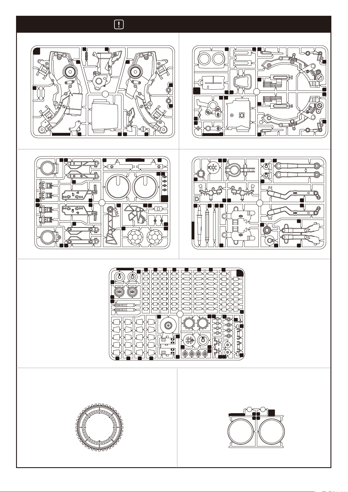
Plastic Parts
Cut off the plastic parts when they are required. Do not cut them in advance.
A
1
3
2
4
5
6
A B
7
C
MADE IN TAIWAN
1
2
3
8
5
6
7
8
11
15 16 17
9 10 11
MADE IN TAIWAN
12
13 14
C
D
B
7
8
MADE IN TAIWAN
1
6 7 8 9
2
5 6
9
3
4 5
1
3
4
2
10
11
12
14
15
13
16
10
11
13
12
14
15
9
4
10
MADE IN TAIWAN
1
3
4
19
5 5 5 5
2
E
18
20
9
8888
MADE IN TAIWAN
6 6 6 7
10
13
11
12 16
14
15
10
19 20
16
E
17
7
18
21
22
18
1917
F G
G
MADE IN TAIWAN
1 1
2 2
2
Page 5
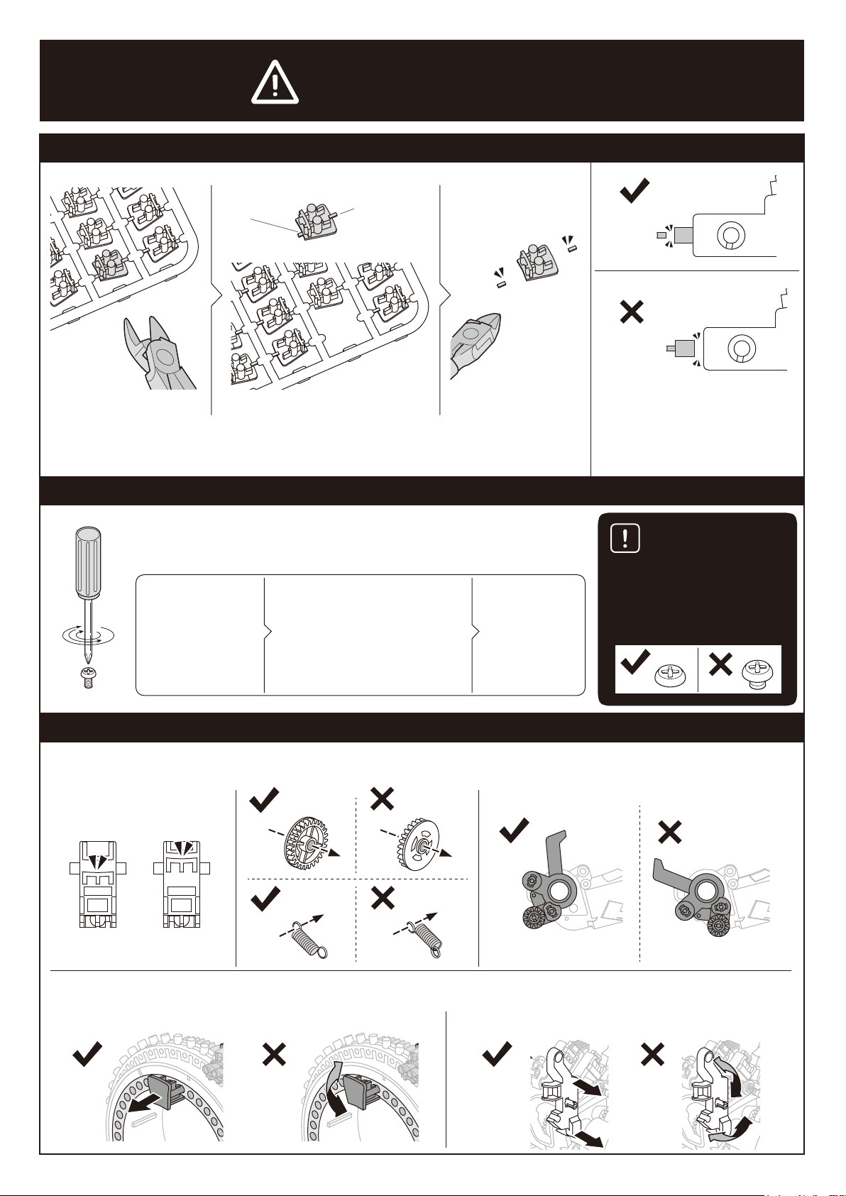
Please Read Before Assembly
Remove burrs
Unnecessary
burrs
Unnecessary
burrs
Some burrs are left at the edge of plastic parts after cutting them off.
Make sure the burrs are completely removed to avoid operation malfunction.
Fasten tapping screws
Use corresponding (size-compatible) screwdriver. By following steps
below, you can fasten the tapping screws perfectly.
Put the screwdriver
towards the top of
screws.
(1) Screw in
(2) Feel the tension getting higher
(3) Keep screwing
Repeat until
screws are
tightly fastened.
Correct
Incorrect
Trim off the burrs ONLY. Do not
trim off the protrusion of the original
plastic parts. All features of parts
should be kept completely.
Please lock screws all the way
down to the bottom. If they are not
fastened tightly enough, parts may
come off. The robot may
consequently not work.
Correct
Incorrect
Shape, assembly direction, and position of parts
Some parts may look quite similar. They should be assembled in the designated direction and position shown in manual.
Correct
Correct
Coding buttons can be removed for new programming. Remove them straight up off the coding wheel. Do not torque them to
avoid damage.
Correct Correct
Incorrect Incorrect
Incorrect
Incorrect
Correct
Incorrect
3
Page 6

Head Module Assembly
1
• Installation, removal and replacement of batteries
should be carried out by an adult or under adult
supervision.
• Avoid short circuiting the contacts in the battery
compartment or the battery terminals.
• Do not mix used batteries and new batteries or
batteries of different types.
• Do not mix alkaline, standard (carbon-zinc) , or
rechargeable (nickel-cadmium) batteries.
• Batteries are to be inserted with the correct polarity.
• Do not attempt to recharge non-rechargeable
batteries.
• Remove exhausted batteries from the product to
avoid leakage.
P12
AAA(x2)
Insert “–” on battery first
Making a mark
B6
Mark
2.36” (6 cm)
1 2 3 4 5 6 7 8 9 12 13 14 15 16 17 18 19 20 21 22 23 24 25 26 27 28 29 3010
cm
Marker Pen (Fine)
Blue
Scale 1:1
Orange
B6
2
A9
B3
B8
P7
4
Page 7
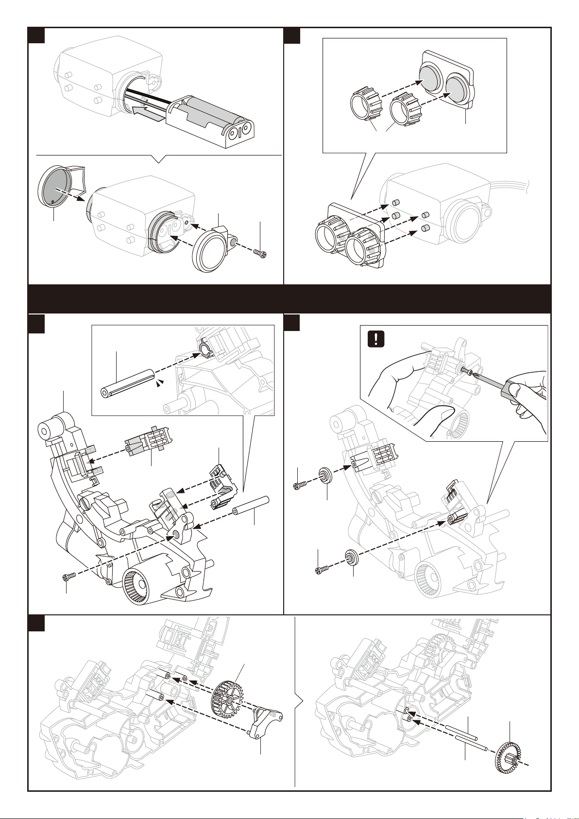
3
4
E12
C4
P7
C1
B1
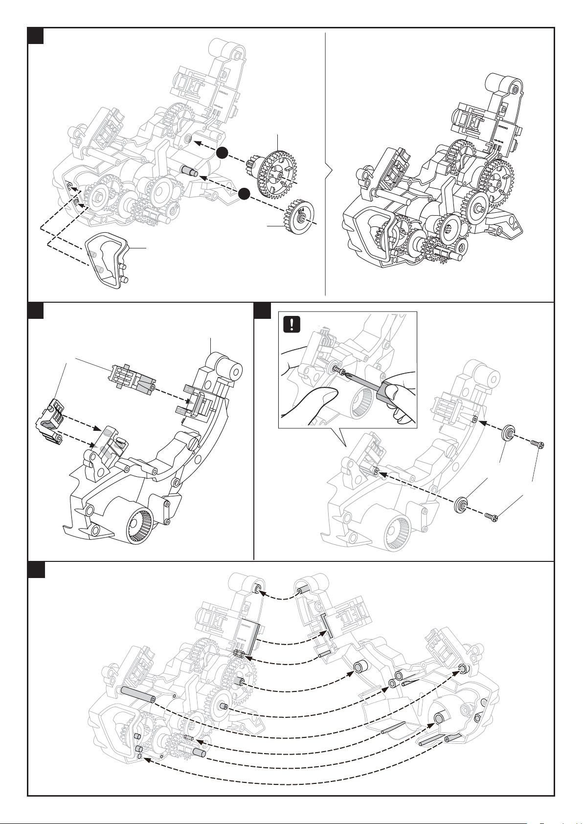
Gear Box Module Assembly
1
E18
A2
2
Tip
C3
P7
C3
E15
E18
P7
E15
P7
3
D2
P6
P2 (Black)
A8
P6
5
Page 8

4
Correct
6
A4
P10
P1
P13
Incorrect
C17
P7
A10
7
B7
2
3
B5
D12
1
Correct
Correct
Incorrect
Incorrect
5
P4 (Orange)
P5 (Black)
Incorrect
8
P3 (Yellow)
P3 (Yellow)
1
2
3
P5 (Black)
P4 (Orange)
P3 (Yellow)
P3 (Yellow)
P7
P2 (Black)
6
Page 9
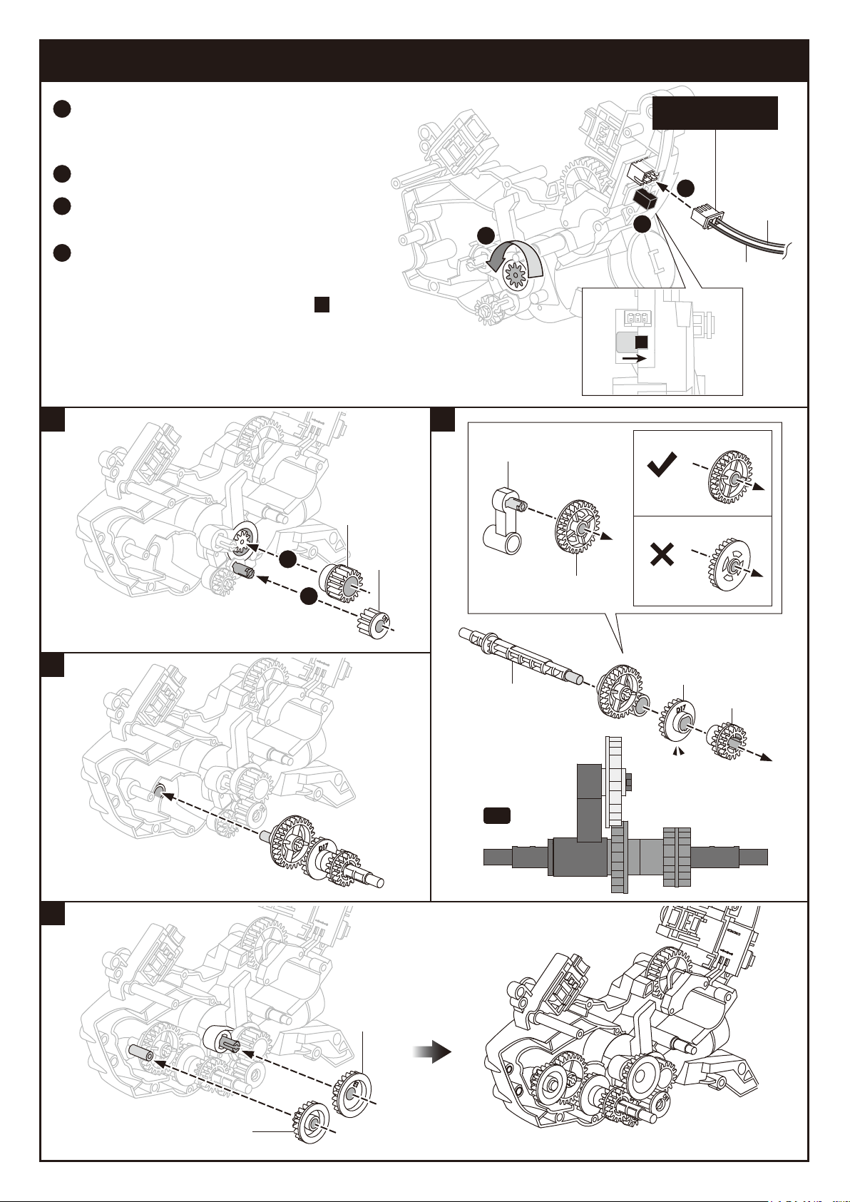
Rear Gear Box Testing (1)
Connect the power supply cable of assembled
1
head (Refer to page 4: Head Module Assembly)
to the terminal base.
Move the switch to the right to turn the power on.
2
The gear will run counterclockwise as
3
illustration.
4
Switch off and remove the power supply
cable after the testing. If the gear box
doesn’t run smoothly or there is abnormal
noise, please go back to page 5 step to
reassemble.
9
Head Module
Power Supply Cable
1
Orange
2
3
Blue
1
10
B9
Correct
D1
11
12
1
2
D11
1:1
D6
E13
Incorrect
D17
D16
E2
E1
7
Page 10
13
1
2
E14
B4
14 15
A5
E9
TipTip
16
C2
E15
P7
8
Page 11

17
P7
P7
Rear Gear Box Testing (2)
Connect the power supply cable of assembled head
1
(refer to page 4: Head Module Assembly) to the terminal base.
2
Move the switch to the right to turn the power on.
3
The gear will run counterclockwise as illustration.
Switch off and remove the power supply cable after the testing.
4
If the gear box doesn’t run smoothly or there is abnormal
noise, please go back to page 5 step to reassemble.
1
Head Module
Power Supply Cable
18
P7
3
2
Correct
1
Orange
Blue
B11
C18
P8
Incorrect
19
C14
B13
B2
A6
A1
G1
9
Page 12

20
B16
C18
P8
21
Correct
B12
Incorrect
C14
B2
A7
22
G1
A1
C13
G2
x2
10
Page 13

23
B14
B15
24
P7x3
25
E22
1
2
E21
1
2
11
Page 14

30 32
A11
31
Correct
Incorrect
33
Completed
2
1
12
Page 15

Accessory Module Assembly
MODULE
1
C7
P11
MODULE
2
P11
C8
MODULE
3
E16
P9
E17
MODULE
4
x2
Coding Wheel Assembly
A3
C19
C20
F
13
Page 16

About the Coding Wheel
CODING WHEEL
Correct
Assignment
coding track
Incorrect
Backward
coding track
Start point
Left
coding track
(Right coding track is on the other side)
How to Install Coding Buttons
Assignment
coding button
(Only for forklift)
E4
Correct
Correct
Correct
Incorrect
Incorrect
Assignment
coding button
E7
Backward
coding button
E8
E5
angle coding button
90 degree
Incorrect
E6
45 degree
angle coding button
Correct
Incorrect
Correct
14
Incorrect
Correct
Incorrect
Page 17

1
Unlock Coding Wheel Clips
How to Install the Coding Wheel
Top View
Push the four
clips as shown
PUSH
PUSH
2
PUSH
PUSHPUSH
PUSH
PUSHPUSH PUSHPUSH
PUSHPUSH
PUSHPUSH
1
1. Rotate clips outward to unlock.
2
2. Tilt shaded section forward.
2
1
1
1
15
Page 18

3
Correct
Coding Wheel Coding Wheel
Incorrect
Set the “Start Point” to
Home Postion
Correct
Incorrect
16
Page 19

4
Pull the four clips outward to secure
coding wheel.
PULL
PULL
PULL
Front View
PULL PULL
PULL
PULL PULL
5 6
1
E21
2
2
E22
17
Page 20

E6
How the Coding Buttons Work
45° Right Turn 90° Right Turn
E8
Right Coding TrackRight Track
45° Left Turn 90° Left Turn
E6
Left Coding TrackLeft Coding Track
E8
18
Page 21

45° Back Right Turn 90° Back Right Turn
Space
Backward Track
E7x2
E6
Right Coding Track
Backward Track
Right Coding Track
E8
E7x3
45° Back Left Turn
Backward Track
E6
Left Coding Track Left Coding Track
90° Back Left Turn
Backward Track
E7x2
Space
E8
E7x3
19
Page 22

Page 23

Drawing-bot AssemblyDrawing-bot Assembly
1
D10
D9
2 3
D3
C15
E19
D7
21
Page 24

4
Marker Pen (Fine)
E19
Scale 1:1
3.75” (9.5 cm)
3.75” (9.5 cm)
Video Tips
To better understand the assembly and operations of each project,
view the sample video listed in Video Tips on the project page.
22
Page 25

Drawing-bot
Parts Required:
Video Tips
View a video on this project at https://www.elenco.com/teachtech/
CODING
CODING WHEEL
Left side
E8
5 pcs
E5x10
Insert the Coding buttons as shown.
Note the position and sequence on both sides of the coding
Start point
E8x5
E5
10 pcs
CODING WHEEL
Right side
Start point
First test the program with the pen cap on. Place the unit on a 2.5’ x 2.5’ piece of paper. Turn the Draw-BOT on,
it moves forward then draws a 13’ diameter circle. Note: Turn the unit off before it repeats the program. Now,
remove the pen cap and run the program again. Using the coding buttons create your own program.
1. If it does not follow the coding program correctly, please go back to page 21 step 2
Trouble Shooting
to check if parts D3 and C15 are assembled in the right way.
2. Check the coding buttons and wheel installation.
3. See page 37
23
Page 26

Forklift-bot Assembly
Forklift-bot Assembly
1
D10
D9
D18
E3
2
E19
D7
E3
D19
3
E19
C16
1
2
24
Page 27

4
C12
MODULE
1
C 11
MODULE
2
E10
E11
B10
B10
5
C10
C6
C9
C5
25
Page 28

Forklift-bot
Parts Required:
E4x2 E5x6 E6x5 E7x6 E8x11
Insert the E8 and E5 buttons as shown.
CODING
Note the position the sequence on both sides of the coding wheel.
CODING
Insert the coding buttons as shown.
Note the position the sequence on both sides of the coding wheel.
View a video on this project at https://www.elenco.com/teachtech/
Video Tips
CODING WHEEL
Left side
E8
6 pcs
E6
2 pcs
E7
6 pcs
E5
6 pcs
E8
5 pcs
E4
CODING WHEEL
Right side
2 pcs
E6
3 pcs
Anytime when you want to add “lifting” to your current coding program,
install mission buttons as illustrated below to enable the movement.
Correct
Incorrect
Trouble Shooting
1. Check the coding buttons and wheel installation, refer to pages 14-15
2. See page 37
26
Page 29

Throwing-bot AssemblyThrowing-bot Assembly
1
E11
C6
C5
C10
C11
E10
C9
Tip : disassemble assembly
as shown below
2
MODULE
Refer to page 12
C12
D15
MODULE
3
3
D14
27
D8
MODULE
3
Page 30

3
2
D7
E19
1
C15
4
4
D13
D13
E20
3
E20
3
2
1
2
E19
28
Page 31

Throwing-bot
Parts Required:
Video Tips
View a video on this project at https://www.elenco.com/teachtech/
CODING
CODING WHEEL
Left side
E8
4 pcs
E5x2 E6x3
E8x10
Insert the coding buttons as shown.
Note the position the sequence on both sides of the coding wheel.
E6
2 pcs
E6
1 pc
E5
2 pcs
CODING WHEEL
Right side
E8
6 pcs
Trouble Shooting
MODULE
4
For safety concern, users should not use any dangerous
materials as throwing object, such as steel balls or sharp items.
1. If it does not follow the coding program correctly, please go back to page 17
step 5 to check if parts E21 and E22 are assembled in the right way.
2. Check the coding buttons and wheel installation
3. See page 37
29
Page 32

Gripper-bot AssemblyGripper-bot Assembly
1
1
D10
D9
E3
D18
E3
D19
2
C5
MODULE
1
D4
C6
MODULE
2
C9
D5
C10
30
Page 33

3
E19
D7
4
MODULE
3
5
C16
6
7
31
E19
Page 34

Gripper-BOT
Parts Required:
CODING
Video Tips
View a video on this project at https://www.elenco.com/teachtech/
E5x9 E6x2 E7x6 E8x9
Insert the coding buttons as shown.
Note the position the sequence on both sides of the coding wheel.
CODING WHEEL
Left side
E8
4 pcs
E7
6 pcs
E6
1 pc
E5
9 pcs
E6
1 pc
CODING WHEEL
Right side
E8
5 pcs
Trouble Shooting
1. If it does not follow the coding program correctly, please go back to page 31
step 5 to check if part C16 is assembled in the right way.
2. Check the coding buttons and wheel installation, refer to pages 13-15
3. See page 37
32
Page 35

Soccer-bot AssemblySoccer-bot Assembly
1
1
MODULE
3
MODULE
3
2
E20
D4
D3
D5
E20
Gear Box
2
D10
D9
33
Page 36

3
4
C16
5
E19
D7
6
E19
C10
D18
C 11
C12
D19
C9
34
Page 37

Soccer-bot
Parts Required:
Video Tips
View a video on this project at https://www.elenco.com/teachtech/
CODING
CODING WHEEL
Left side
E8
2 pcs
E5x4
Insert the coding buttons as shown.
Note the position the sequence on both sides of the coding wheel.
E8x5
E5
4 pcs
CODING WHEEL
Right side
E8
3 pcs
Trouble Shooting
MODULE
4
1. If it does not follow the coding program correctly, please go back to page 34
step 4 to check if part C16 is assembled in the right way.
2. Check the coding buttons and wheel installation, refer to pages 13-15
3. See page 37
35
Page 38

How to Replace the Batteries
1
REMOVE
2
3
REMOVE
Battery( AAA) x 2
Insert “–” on battery first
Removal and replacement of batteries should be carried out by
adults or under adult supervision.
Avoid short circuiting the contacts in the battery compartment or
the battery terminals.
Do not mix used batteries and new batteries or batteries of different
types.
Do not mix alkaline, standard (carbon-zinc) , or rechargeable
(nickel-cadmium) batteries.
Batteries are to be inserted with the correct polarity.
Do not attempt to recharge non-rechargeable batteries.
Remove exhausted batteries from the product to avoid leakage.
36
Page 39

Trouble Shooting
1. Ensure all coding buttons are assembled correctly (refer to page 14).
2. Ensure the coding wheel is assembled correctly (refer to pages 15–17, steps – ).
1 6
3. If the robot does not move smoothly or appropriately when turning right/left or stopping,
18
please go back to pages 9–10 and ensure steps – are correctly executed.
21
4. If the robot does not move smoothly or appropriately when going backward, please go
back to page 6 step to check if parts B5, B7, and D12 are assembled in the right way.
7
5. If the Drawing-bot does not follow the coding program correctly, please go back to page
21 step to check if parts D3 and C15 are assembled in the right way.
2
6. If the Forklift-bot does not follow the coding program correctly, please go back to page 26
to check if part E5 is assembled in the right way.
7. If the Throwing-bot does not follow the coding program correctly, please go back to
page 17 step to check if parts E21 and E22 are assembled in the right way.
5
8. If the Gripper-bot does not follow the coding program correctly, please go back to page 31
5
step to check if part C16 is assembled in the right way.
9. If the Soccer-bot does not follow the coding program correctly, please go back to page 34
4
step to check if part C16 is assembled in the right way.
37
Page 40

150 Carpenter Ave.
Wheeling, IL 60090, USA
(847) 541-3800 or (800) 533-2441
elenco.com
CHOKING HAZARD. Small Parts.
Not for children under 3 years old.
No part of this book shall be reproduced by any means: electronic, photocopying,
or otherwise without written permission from the publisher.
Printed in Taiwan
Patents Pending
Not responsible for typographical errors.
Teach TechTM is a trademark of Elenco Electronics Inc.
Copyright© 2019 Elenco Electronics Inc. All rights reserved.
753173
4350008951
 Loading...