

Page 1
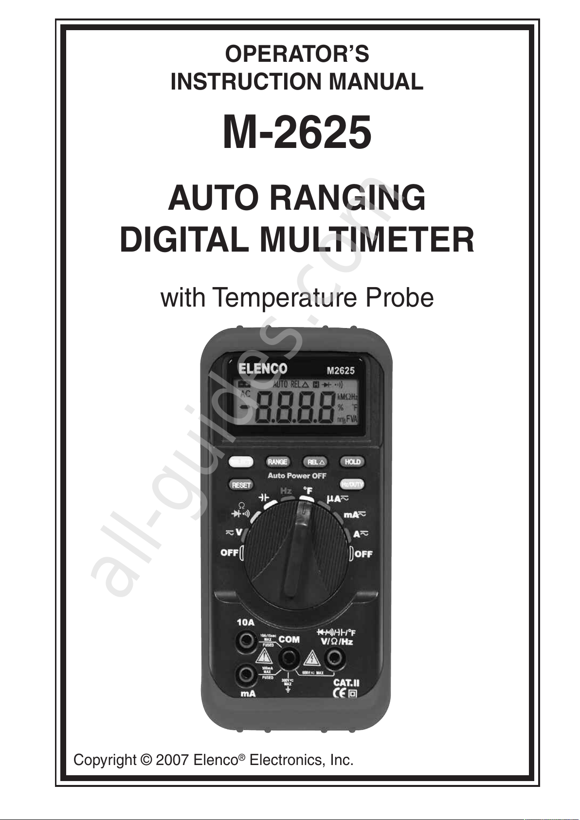
OPERATOR’S
INSTRUCTION MANUAL
M-2625
AUTO RANGING
DIGITAL MULTIMETER
with Temperature Probe
Copyright © 2007 Elenco®Electronics, Inc.
All manuals and user guides at all-guides.com
all-guides.com
Page 2
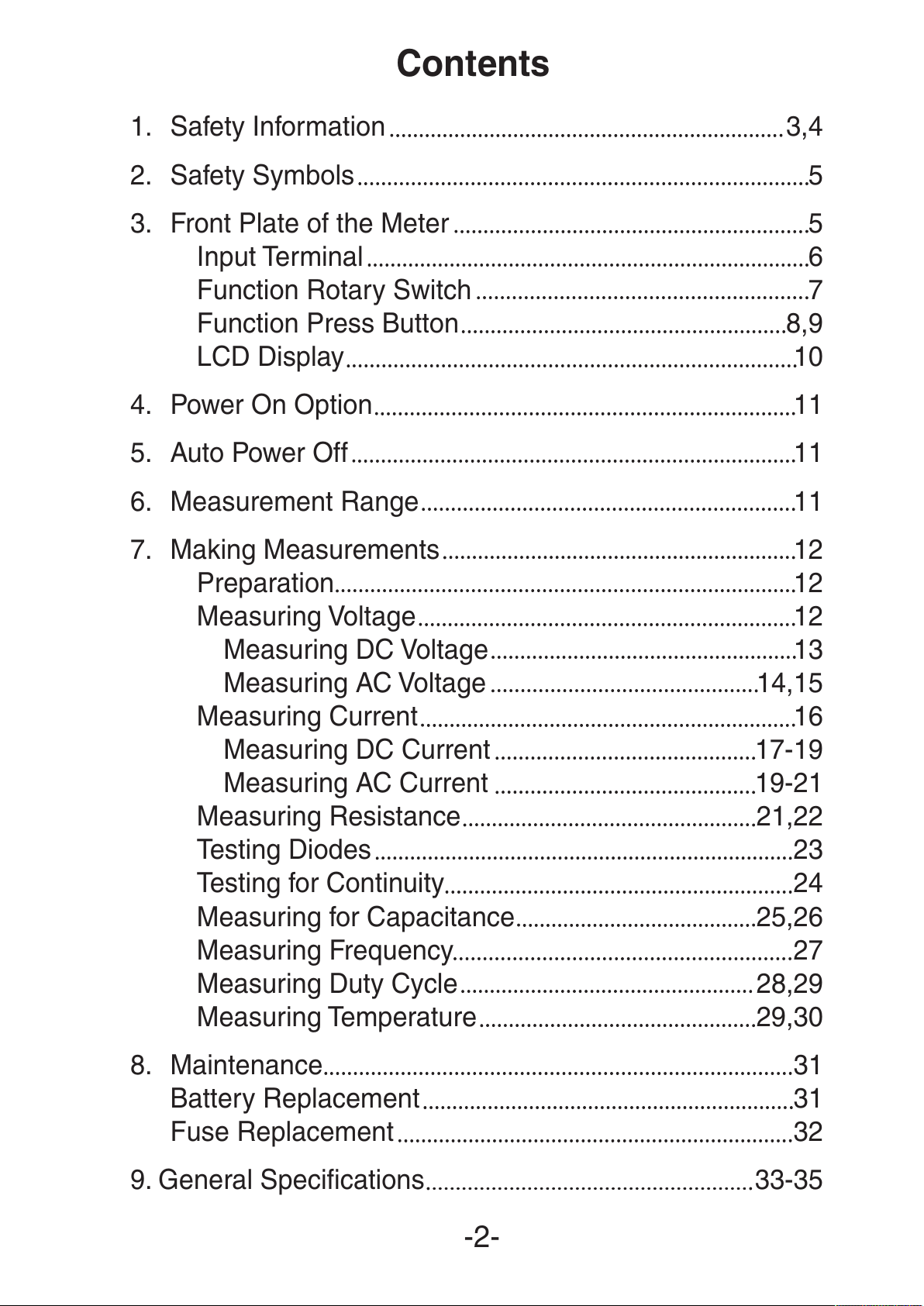
Contents
1. Safety Information 3,4
2. Safety Symbols 5
3. Front Plate of the Meter 5
Input Terminal 6
Function Rotary Switch 7
Function Press Button 8,9
LCD Display 10
4. Power On Option 11
5. Auto Power Off 11
6. Measurement Range 11
7. Making Measurements 12
Preparation 12
Measuring Voltage 12
Measuring DC Voltage 13
Measuring AC Voltage 14,15
Measuring Current 16
Measuring DC Current 17-19
Measuring AC Current 19-21
Measuring Resistance 21,22
Testing Diodes 23
Testing for Continuity 24
Measuring for Capacitance 25,26
Measuring Frequency 27
Measuring Duty Cycle 28,29
Measuring Temperature 29,30
8. Maintenance 31
Battery Replacement 31
Fuse Replacement 32
9. General Specifications 33-35
-2-
All manuals and user guides at all-guides.com
Page 3
Introduction
This series LCD auto ranging and auto power-off digital multimeter
is a portable, compact, 3¾ digit multimeter. It is ideally suited for
field, lab, shop, car, and home.
CAUTION: Read, understand and follow all Safety Rules and
Operating Instructions in this manual before using this product.
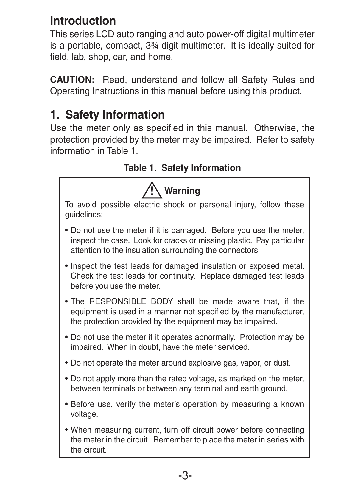
1. Safety Information
Use the meter only as specified in this manual. Otherwise, the
protection provided by the meter may be impaired. Refer to safety
information in Table 1.
Table 1. Safety Information
Warning
To avoid possible electric shock or personal injury, follow these
guidelines:
• Do not use the meter if it is damaged. Before you use the meter,
inspect the case. Look for cracks or missing plastic. Pay particular
attention to the insulation surrounding the connectors.
• Inspect the test leads for damaged insulation or exposed metal.
Check the test leads for continuity. Replace damaged test leads
before you use the meter.
• The RESPONSIBLE BODY shall be made aware that, if the
equipment is used in a manner not specified by the manufacturer,
the protection provided by the equipment may be impaired.
• Do not use the meter if it operates abnormally. Protection may be
impaired. When in doubt, have the meter serviced.
• Do not operate the meter around explosive gas, vapor, or dust.
• Do not apply more than the rated voltage, as marked on the meter,
between terminals or between any terminal and earth ground.
• Before use, verify the meter’s operation by measuring a known
voltage.
• When measuring current, turn off circuit power before connecting
the meter in the circuit. Remember to place the meter in series with
the circuit.
-3-
!
All manuals and user guides at all-guides.com
Page 4
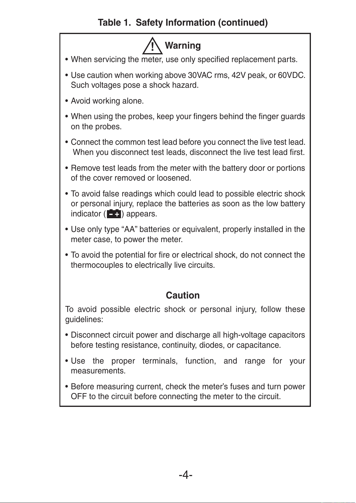
Table 1. Safety Information (continued)
Warning
• When servicing the meter, use only specified replacement parts.
• Use caution when working above 30VAC rms, 42V peak, or 60VDC.
Such voltages pose a shock hazard.
• Avoid working alone.
• When using the probes, keep your fingers behind the finger guards
on the probes.
• Connect the common test lead before you connect the live test lead.
When you disconnect test leads, disconnect the live test lead first.
• Remove test leads from the meter with the battery door or portions
of the cover removed or loosened.
• To avoid false readings which could lead to possible electric shock
or personal injury, replace the batteries as soon as the low battery
indicator ( ) appears.
• Use only type “AA” batteries or equivalent, properly installed in the
meter case, to power the meter.
• To avoid the potential for fire or electrical shock, do not connect the
thermocouples to electrically live circuits.
Caution
To avoid possible electric shock or personal injury, follow these
guidelines:
• Disconnect circuit power and discharge all high-voltage capacitors
before testing resistance, continuity, diodes, or capacitance.
• Use the proper terminals, function, and range for your
measurements.
• Before measuring current, check the meter’s fuses and turn power
OFF to the circuit before connecting the meter to the circuit.
-4-
!
+
All manuals and user guides at all-guides.com
Page 5
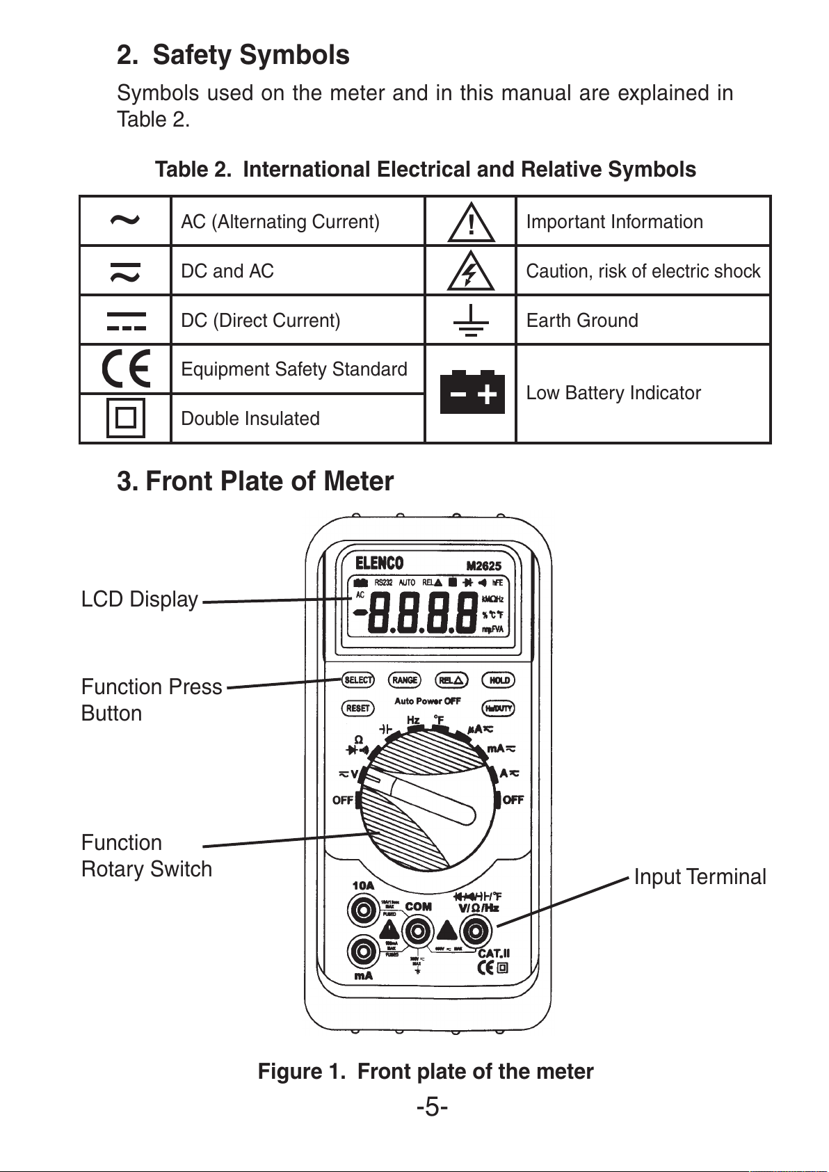
2. Safety Symbols
Symbols used on the meter and in this manual are explained in
Table 2.
Table 2. International Electrical and Relative Symbols
3. Front Plate of Meter
Figure 1. Front plate of the meter
-5-
~
AC (Alternating Current) Important Information
~
DC and AC
Caution, risk of electric shock
DC (Direct Current) Earth Ground
Equipment Safety Standard
Low Battery Indicator
Double Insulated
!
+
LCD Display
Function Press
Button
Function
Rotary Switch
Input Terminal
All manuals and user guides at all-guides.com
Page 6
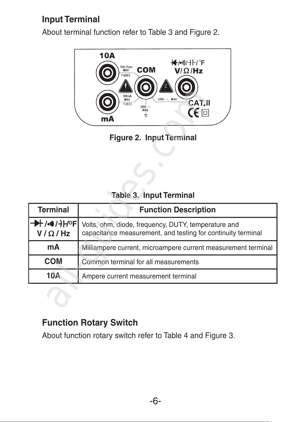
Input Terminal
About terminal function refer to Table 3 and Figure 2.
Figure 2. Input Terminal
Table 3. Input Terminal
Function Rotary Switch
About function rotary switch refer to Table 4 and Figure 3.
-6-
Terminal Function Description
/ /)/OF
V /
ΩΩ
/ Hz
Volts, ohm, diode, frequency, DUTY, temperature and
capacitance measurement, and testing for continuity terminal
mA
Milliampere current, microampere current measurement terminal
COM
Common terminal for all measurements
10A
Ampere current measurement terminal
All manuals and user guides at all-guides.com
all-guides.com
Page 7
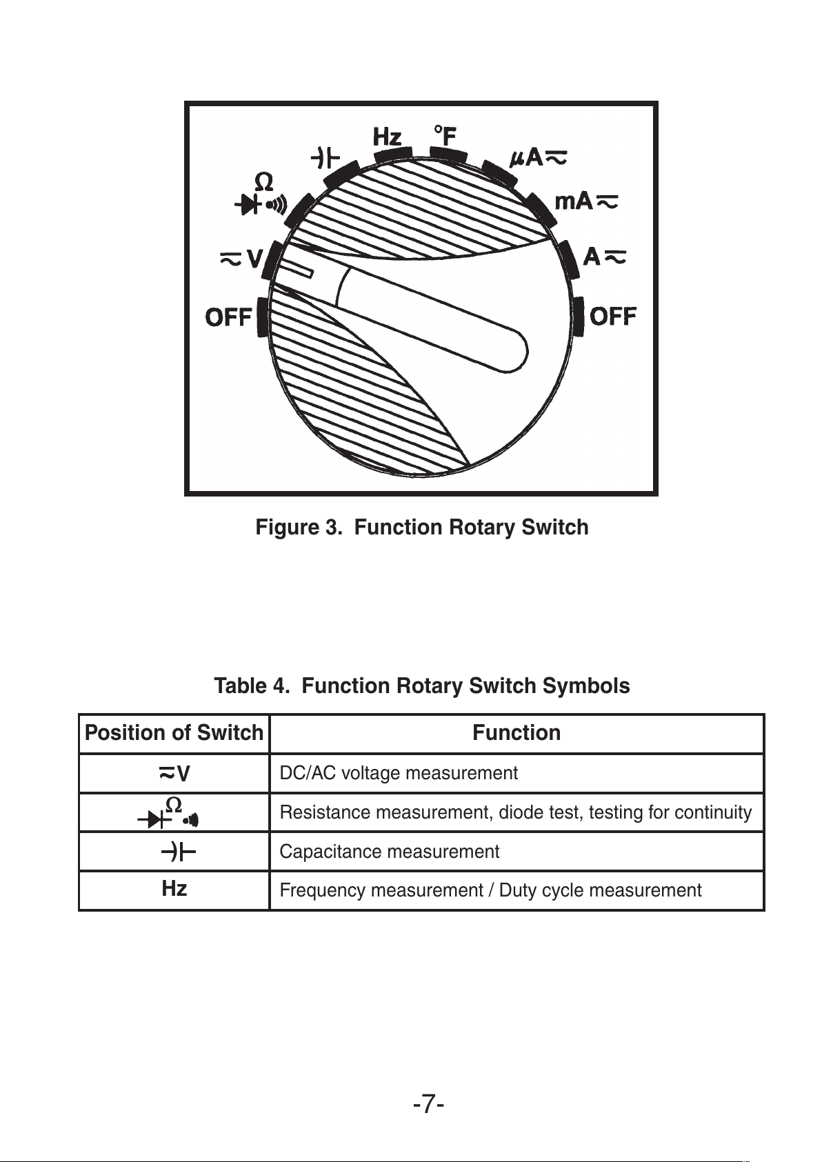
Figure 3. Function Rotary Switch
Table 4. Function Rotary Switch Symbols
-7-
Position of Switch
Function
~
V
DC/AC voltage measurement
ΩΩ
Resistance measurement, diode test, testing for continuity
)
Capacitance measurement
Hz
Frequency measurement / Duty cycle measurement
All manuals and user guides at all-guides.com
Page 8

Table 4. Function Rotary Switch Symbols (continued)
Function Press Button
About press function button refer to Figure 4.
Figure 4. Function Press Button
1. SELECT (state choice)
There are several functions at one rotary switch position; press the
SELECT button to select the desired function: ~V,
ΩΩ
, µµA~, mA~,
A~ range for AC or DC voltage, AC or DC current, resistance,
diode, or audible continuity measurement.
2. RANGE (range selection)
With the power on and the meter on the auto range mode, press the
RANGE button to select the desired measurement range manually.
The range goes from minimum to maximum by pressing the
RANGE button multiple times, and returns to minimum after
reaching the maximum range. Pressing and holding the RANGE
button for over two seconds returns the meter to auto range. This
button does not affect the frequency, capacitance, diode or
continuity range.
-8-
Position of Switch
Function
O
F
Temperature measurement
µµ
A
~
DC/AC microampere current measurement
mA
~
DC/AC milliampere current measurement
A
~
DC/AC ampere current measurement
OFF
Power off position
All manuals and user guides at all-guides.com
Page 9
3. REL∆∆(relative measurement)
Press the REL
∆∆
button to use the relative measuring function and
a “REL∆” symbol appears on the LCD. The result of the relative
measurement is the difference between the measuring value and
the reference value. The reference value is produced the same as
the momentary value by press the REL
∆∆
button. Press the REL
∆∆
button again to exit this function and the “REL∆” symbol disappears
from the display. This button does not affect the frequency, duty
cycle, diode and continuity test functions.
4. HOLD (data hold)
Pressing the HOLD button enables the data hold function and an
“ H ” symbol appears on the display. The momentary value appears
on the display. Press the HOLD button again to exit this function
and the “ H ” symbol disappears from the display. This button does
not affect the frequency measurement function.
5. Hz/DUTY
(frequency and duty cycle measurement switch button)
When making a frequency, DC or AC voltage measurement, press
this button to switch between the Hz or duty cycle test mode.
6. RESET (reset button)
Press this button to clear all values and to restart the meter.
LCD Display
About function rotary switch refer to Table 5 and Figure 5.
-9-
All manuals and user guides at all-guides.com
Page 10

Figure 5. LCD Display
Table 5. LCD Display Symbols
-10-
Sequ. No. Symbol Description
1 8.8.8.8
The display digit group
2 –
Negative symbol
3 AC
AC (alternating current) indicator
4
Battery power is weakening
5 RS232
Serial transmission (not used on this meter)
6 Auto
Auto range indicator
7 REL
∆∆
Relative measurement
8
Data hold
9
Diode symbol
10
Audible continuity function indicator
11 hFE
Transistor gain indicator (not used)
12
ΩΩ
/ kΩΩ/ M
ΩΩ
Hz / kHz / MHz
Resistance units
Frequency units
+
H
All manuals and user guides at all-guides.com
Page 11
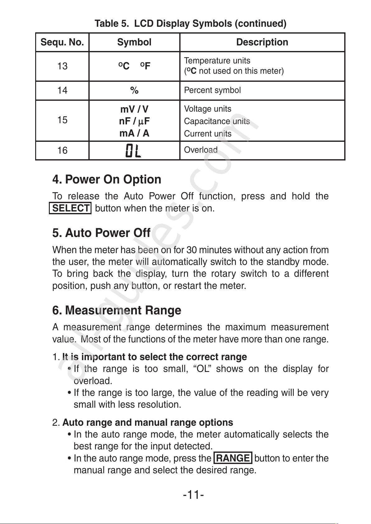
Table 5. LCD Display Symbols (continued)
4. Power On Option
To release the Auto Power Off function, press and hold the
SELECT button when the meter is on.
5. Auto Power Off
When the meter has been on for 30 minutes without any action from
the user, the meter will automatically switch to the standby mode.
To bring back the display, turn the rotary switch to a different
position, push any button, or restart the meter.
6. Measurement Range
A measurement range determines the maximum measurement
value. Most of the functions of the meter have more than one range.
1. It is important to select the correct range
• If the range is too small, “OL” shows on the display for
overload.
• If the range is too large, the value of the reading will be very
small with less resolution.
2. Auto range and manual range options
• In the auto range mode, the meter automatically selects the
best range for the input detected.
• In the auto range mode, press the RANGE button to enter the
manual range and select the desired range.
-11-
Sequ. No. Symbol Description
13
O
C OF
Temperature units
(
O
C not used on this meter)
14 %
Percent symbol
15
mV / V
nF / µµF
mA / A
Voltage units
Capacitance units
Current units
16
Overload
All manuals and user guides at all-guides.com
all-guides.com
Page 12

• When you change the measurement function, the meter will
regard its auto range as current range.
• In the auto range mode, the “AUTO” symbol will appear on
display and the manual range disappears.
3. Enter or exit manual range mode
• Press the RANGE button to select the manual range mode
and the “AUTO” symbol disappears. Each press of the
RANGE button increases the range. When the maximum
range is reached, the meter restarts at the lowest range.
• Press and hold the RANGE button for more than two
seconds to return to the autorange mode and the “AUTO”
symbol will appear on the display.
7. Making Measurements
Preparation
Checking the Battery Voltage
Rotate the Function Rotary Switch to any position away from the
OFF position. The battery voltage is adequate when the indication
is clear and the symbol is not on the display.
If the symbol appears on the display, or nothing shows on the
display at all, follow the battery replacement procedure shown in
related items in this manual and replace with new batteries specified.
Measuring Voltage
Voltage is the difference in electrical potential between two points.
The polarity of AC (alternating current) voltage varies over time, while
the polarity of DC (direct current) voltage is constant.
Danger
To avoid the danger of electric shock, never make measurements
on a circuit over 600V AC/DC (electrical potential to ground 300V
DC/AC). Do not operate the Function Rotary Switch during
measurement. Do not make a measurement when opening the
battery cover and the meter case.
-12-
+
+
!
All manuals and user guides at all-guides.com
Page 13

Measuring DC Voltage
1. Turn on the meter, then set up the meter to measure DC volts as
shown in Figure 6.
2. Insert the black test lead into the COM terminal and the red test
lead into the terminal.
3. Set the Function Rotary Switch to the ~V position (then, “AUTO”
and “mV” symbols are indicated on the display).
4. Connect the black test lead to the negative side of the circuit
under test and the red test lead to the positive side of the circuit.
The measured value is indicated on the display. If you connect
the test leads to the opposite polarity, the “–” symbol appears on
the display.
Figure 6. DC Voltage Measurement
-13-
All manuals and user guides at all-guides.com
Page 14

Measuring AC Voltage
1. Turn on the meter, then set up the meter to measure AC volts as
shown in Figure 7.
2. Insert the black test lead into the COM terminal and the red test
lead into the terminal.
3. Set the Function Rotary Switch to the ~V position and press
SELECT to select the AC voltage measuring mode (then,
“AUTO”, “AC” and “V” symbols are indicated on the display).
4. Connect the test leads to the circuit under test, then the
measured value is indicated on the display.
5. When measuring voltage less than 400mV, press the RANGE
button to switch to manual range mode and select the AC 400mV
range. Doing so will provide a better resolution for your
measurement.
6. You can press the Hz/DUTY button to read the signal frequency
or duty cycle under measurement from the display.
-14-
All manuals and user guides at all-guides.com
Page 15
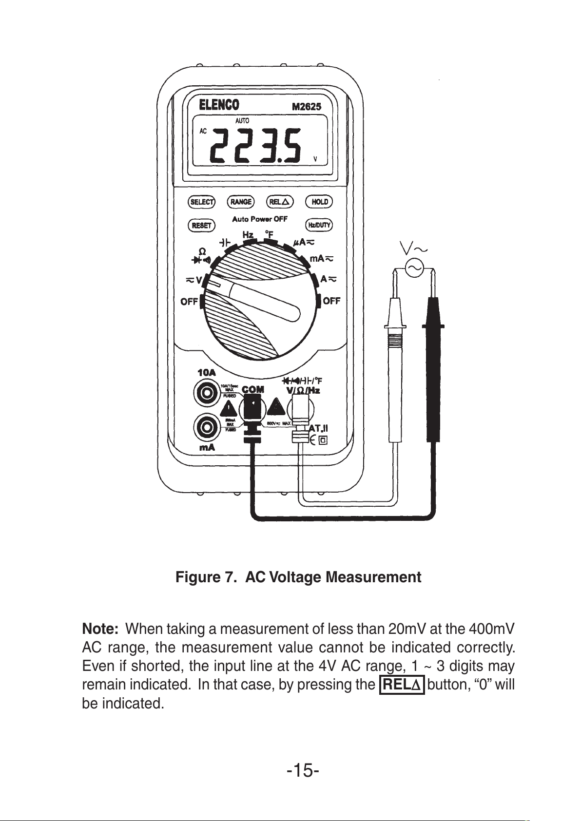
Figure 7. AC Voltage Measurement
Note: When taking a measurement of less than 20mV at the 400mV
AC range, the measurement value cannot be indicated correctly.
Even if shorted, the input line at the 4V AC range, 1 ~ 3 digits may
remain indicated. In that case, by pressing the REL
∆
∆
button, “0” will
be indicated.
-15-
All manuals and user guides at all-guides.com
Page 16
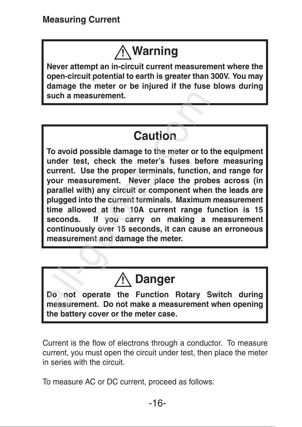
Measuring Current
Warning
Never attempt an in-circuit current measurement where the
open-circuit potential to earth is greater than 300V. You may
damage the meter or be injured if the fuse blows during
such a measurement.
Caution
To avoid possible damage to the meter or to the equipment
under test, check the meter’s fuses before measuring
current. Use the proper terminals, function, and range for
your measurement. Never place the probes across (in
parallel with) any circuit or component when the leads are
plugged into the current terminals. Maximum measurement
time allowed at the 10A current range function is 15
seconds. If you carry on making a measurement
continuously over 15 seconds, it can cause an erroneous
measurement and damage the meter.
Danger
Do not operate the Function Rotary Switch during
measurement. Do not make a measurement when opening
the battery cover or the meter case.
Current is the flow of electrons through a conductor. To measure
current, you must open the circuit under test, then place the meter
in series with the circuit.
To measure AC or DC current, proceed as follows:
-16-
!
!
All manuals and user guides at all-guides.com
all-guides.com
Page 17
Measuring DC Current
1. Turn off power to the circuit. Discharge all high-voltage
capacitors.
2. Turn on the meter, then set up the meter to measure DC current
as shown in Figure 8.
3. Insert the black test lead into the COM terminal and the red lead
into an input appropriate for the measurement range as shown
in Table 6.
4. Connect the black test lead to the negative side of the circuit
under test and the red test lead to the positive side of the circuit
so the meter is in series with the circuit.
5. Turn the on the power for the circuit under test.
6. The measured value is indicated on the display.
If you connect the test leads to the reverse polarities, a “–” symbol
will be shown on the display.
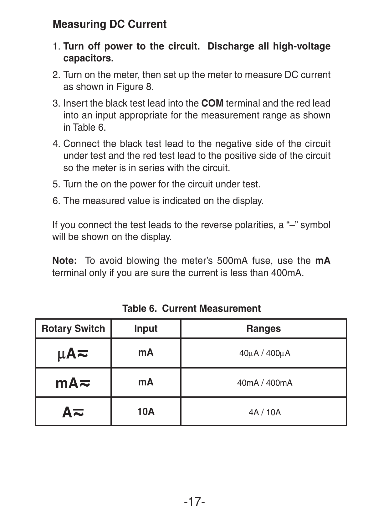
Note: To avoid blowing the meter’s 500mA fuse, use the mA
terminal only if you are sure the current is less than 400mA.
Table 6. Current Measurement
-17-
Rotary Switch Input Ranges
µµ
A
~
mA
40µA / 400µA
mA
~
mA
40mA / 400mA
A
~
10A
4A / 10A
All manuals and user guides at all-guides.com
Page 18
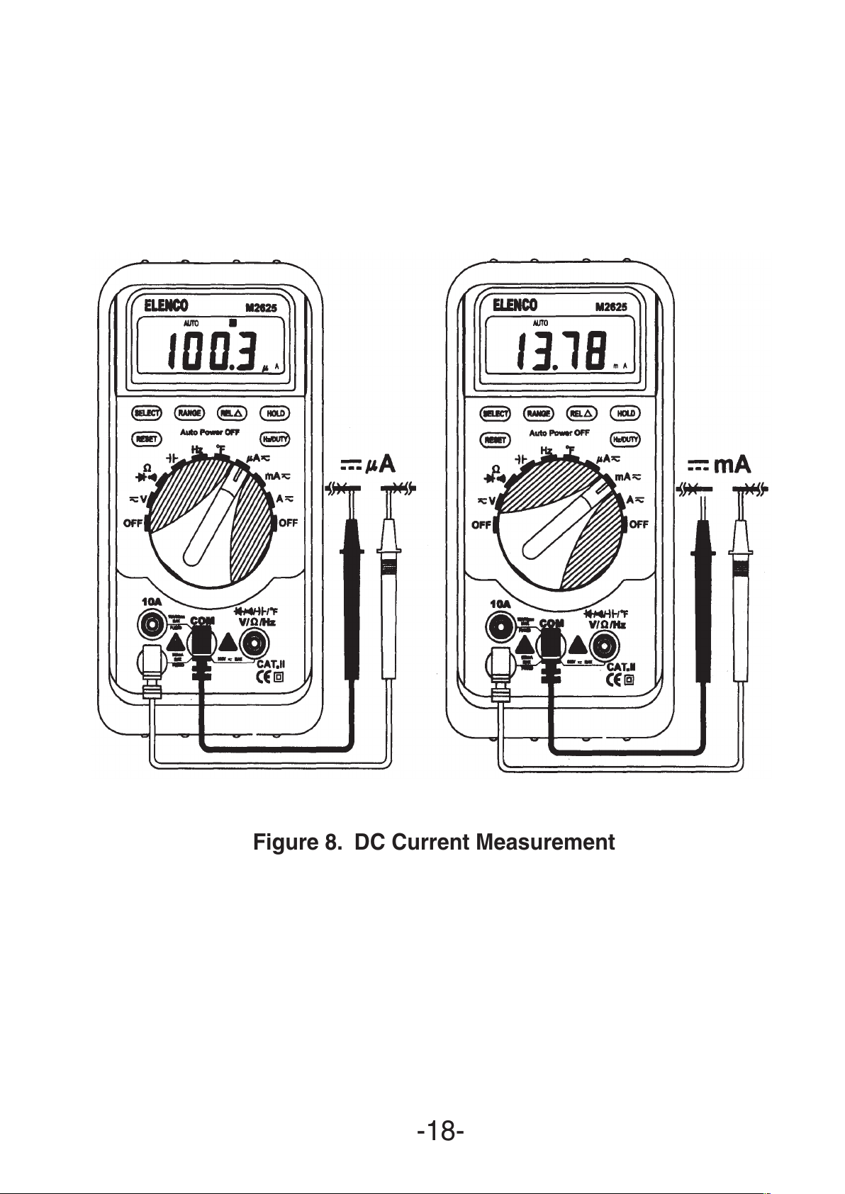
Figure 8. DC Current Measurement
-18-
All manuals and user guides at all-guides.com
Page 19
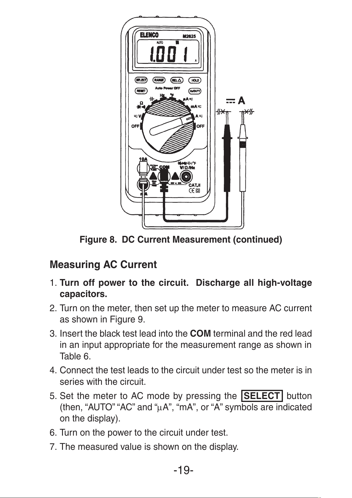
Figure 8. DC Current Measurement (continued)
Measuring AC Current
1. Turn off power to the circuit. Discharge all high-voltage
capacitors.
2. Turn on the meter, then set up the meter to measure AC current
as shown in Figure 9.
3. Insert the black test lead into the COM terminal and the red lead
in an input appropriate for the measurement range as shown in
Table 6.
4. Connect the test leads to the circuit under test so the meter is in
series with the circuit.
5. Set the meter to AC mode by pressing the SELECT button
(then, “AUTO” “AC” and “µA”, “mA”, or “A” symbols are indicated
on the display).
6. Turn on the power to the circuit under test.
7. The measured value is shown on the display.
-19-
All manuals and user guides at all-guides.com
Page 20
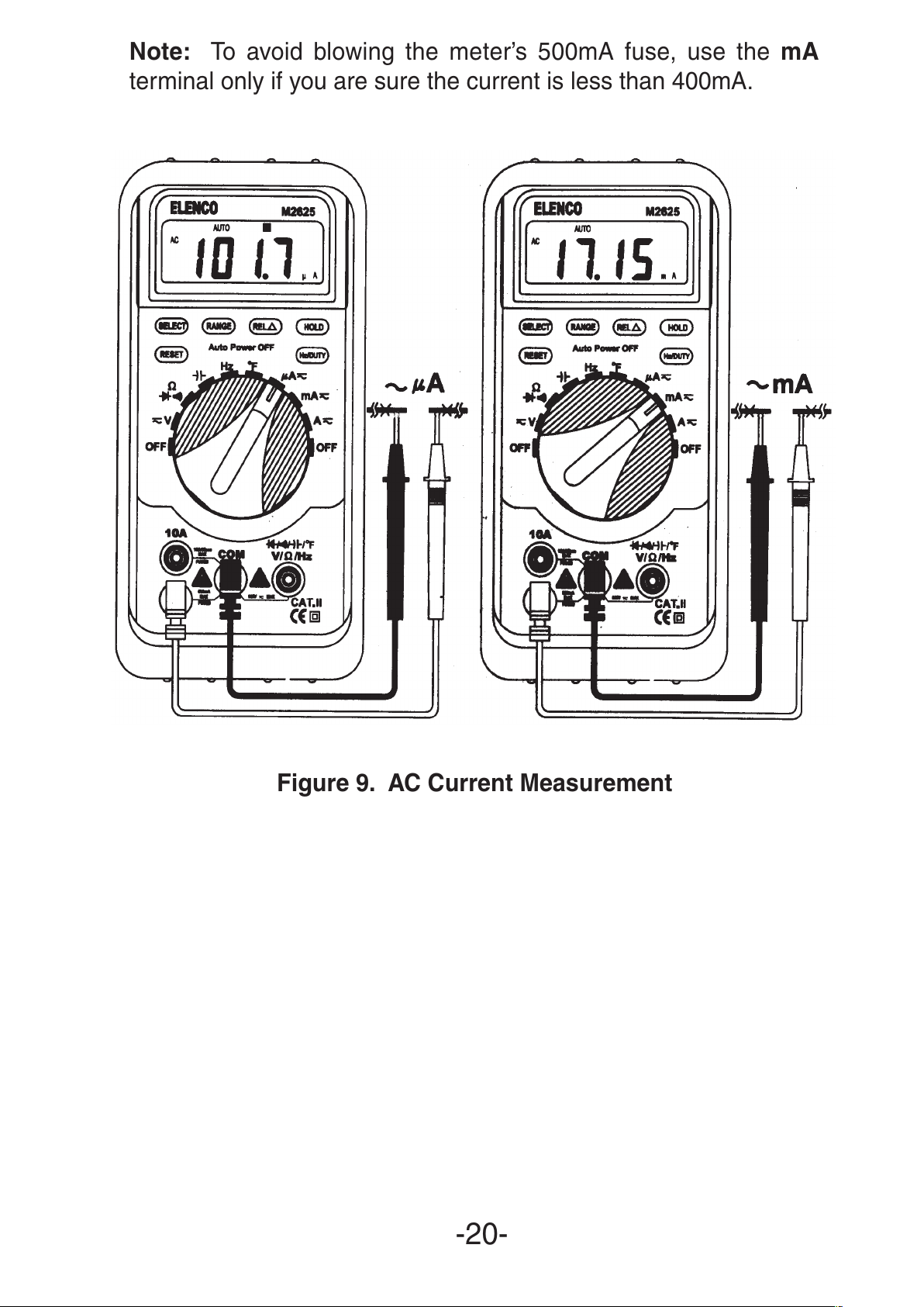
Note: To avoid blowing the meter’s 500mA fuse, use the mA
terminal only if you are sure the current is less than 400mA.
Figure 9. AC Current Measurement
-20-
All manuals and user guides at all-guides.com
Page 21
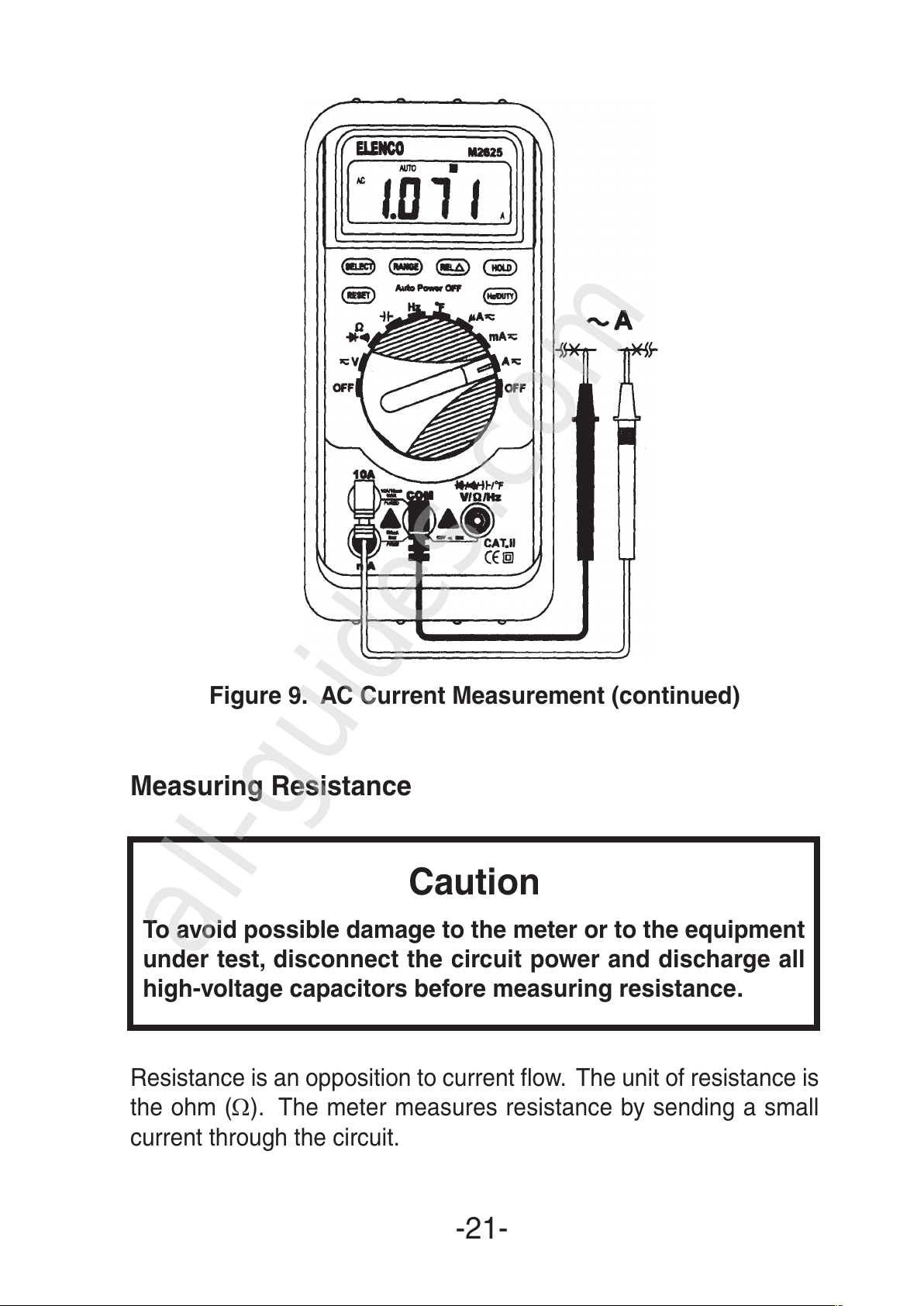
Figure 9. AC Current Measurement (continued)
Measuring Resistance
Caution
To avoid possible damage to the meter or to the equipment
under test, disconnect the circuit power and discharge all
high-voltage capacitors before measuring resistance.
Resistance is an opposition to current flow. The unit of resistance is
the ohm (Ω). The meter measures resistance by sending a small
current through the circuit.
-21-
All manuals and user guides at all-guides.com
all-guides.com
Page 22
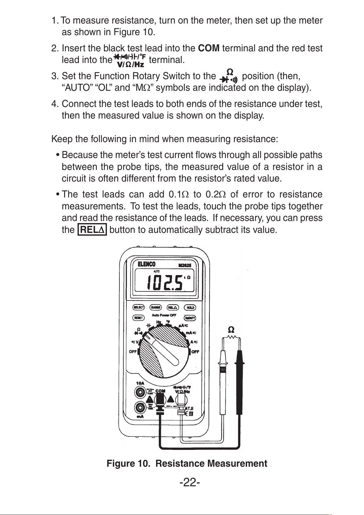
1. To measure resistance, turn on the meter, then set up the meter
as shown in Figure 10.
2. Insert the black test lead into the COM terminal and the red test
lead into the terminal.
3. Set the Function Rotary Switch to the position (then,
“AUTO” “OL” and “MΩ” symbols are indicated on the display).
4. Connect the test leads to both ends of the resistance under test,
then the measured value is shown on the display.
Keep the following in mind when measuring resistance:
• Because the meter’s test current flows through all possible paths
between the probe tips, the measured value of a resistor in a
circuit is often different from the resistor’s rated value.
• The test leads can add 0.1Ω to 0.2Ω of error to resistance
measurements. To test the leads, touch the probe tips together
and read the resistance of the leads. If necessary, you can press
the REL
∆∆
button to automatically subtract its value.
Figure 10. Resistance Measurement
-22-
All manuals and user guides at all-guides.com
Page 23
Testing Diodes
Caution
To avoid possible damage to the meter or to the equipment
under test, disconnect the circuit power and discharge all
high-voltage capacitors before testing diodes.
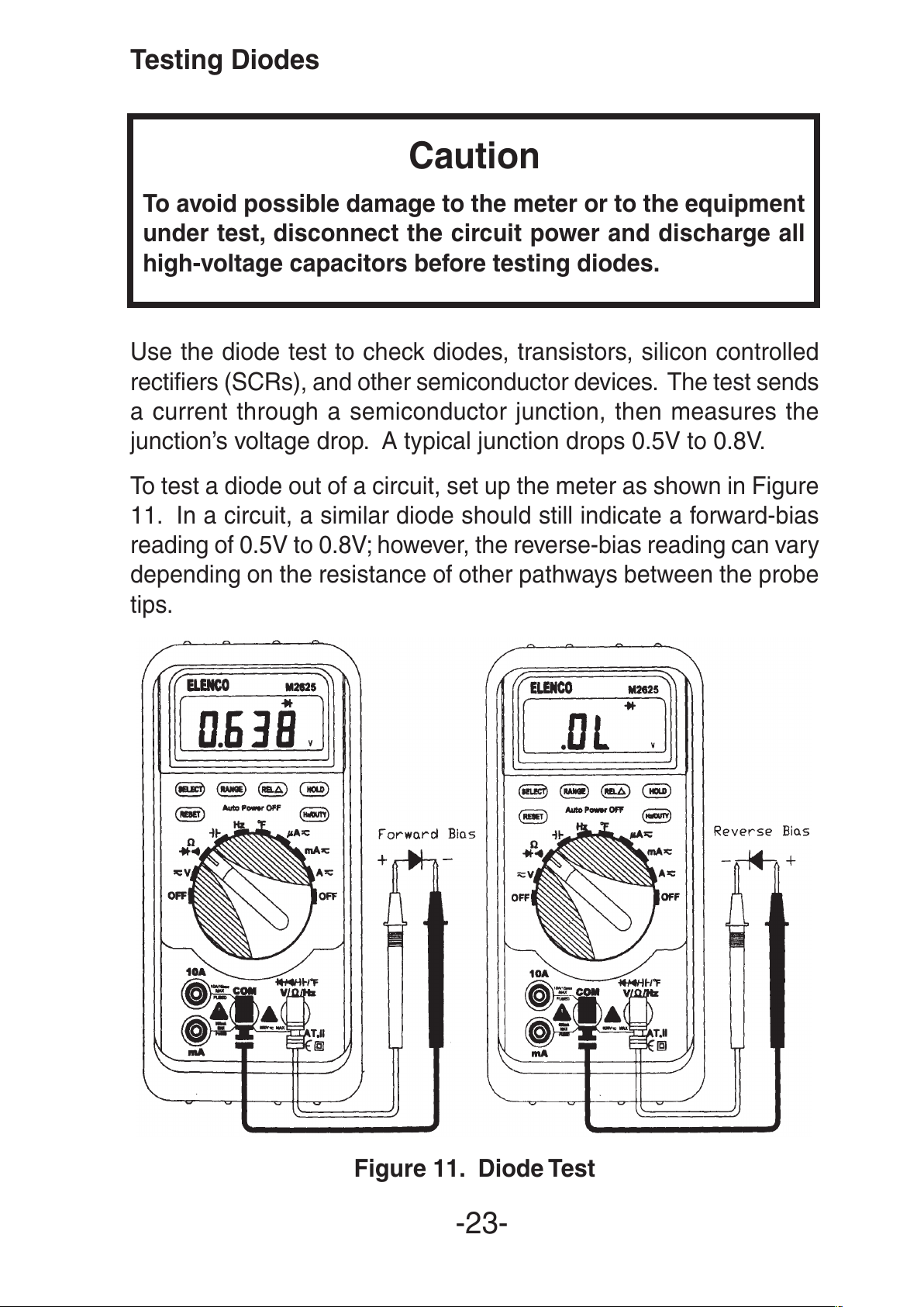
Use the diode test to check diodes, transistors, silicon controlled
rectifiers (SCRs), and other semiconductor devices. The test sends
a current through a semiconductor junction, then measures the
junction’s voltage drop. A typical junction drops 0.5V to 0.8V.
To test a diode out of a circuit, set up the meter as shown in Figure
11. In a circuit, a similar diode should still indicate a forward-bias
reading of 0.5V to 0.8V; however, the reverse-bias reading can vary
depending on the resistance of other pathways between the probe
tips.
Figure 11. Diode Test
-23-
All manuals and user guides at all-guides.com
Page 24
Note: Open-circuit voltage between measuring terminals is
approximately 1.5V (measuring current approximately 1.5mA).
Testing for Continuity
Caution
To avoid possible damage to the meter or to the equipment
under test, disconnect the circuit power and discharge all
high-voltage capacitors before testing for continuity.
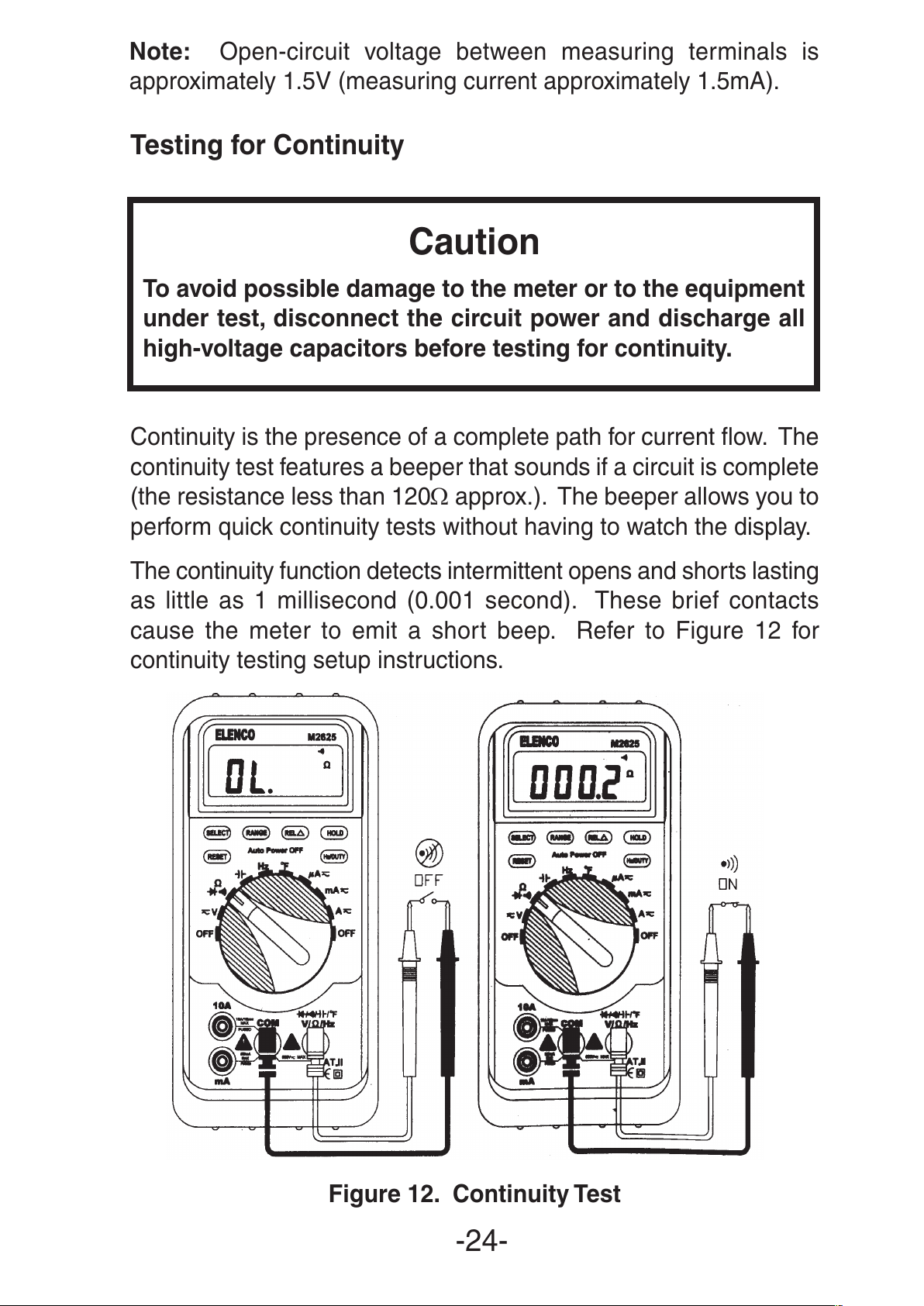
Continuity is the presence of a complete path for current flow. The
continuity test features a beeper that sounds if a circuit is complete
(the resistance less than 120Ω approx.). The beeper allows you to
perform quick continuity tests without having to watch the display.
The continuity function detects intermittent opens and shorts lasting
as little as 1 millisecond (0.001 second). These brief contacts
cause the meter to emit a short beep. Refer to Figure 12 for
continuity testing setup instructions.
Figure 12. Continuity Test
-24-
All manuals and user guides at all-guides.com
Page 25
Keep the following in mind while doing a continuity test:
• Even with the test leads shorted, the indicated value may not be
“0”. This is because of the resistance of the test leads and not a
fault. If necessary, you can press the REL
∆∆
button to
automatically subtract its value, then “0” will be indicated.
Measuring Capacitance
Caution
To avoid possible damage to the meter or to the equipment under
test, disconnect the circuit power and discharge all high-voltage
capacitors before measuring capacitance. Use the DC voltage
function to confirm that the capacitor is indeed discharged.
Capacitance is the ability of a component to store an electrical
charge. The unit of capacitance is the farad (F). Most capacitors
are in the nanofarad (nF) to microfarad (µF) range.
The meter measures capacitance by charging the capacitor with a
known current for a known period of time according to the
measuring capacitance:
Measuring capacitance <4µF Measuring time is about 2 seconds
Measuring capacitance <40µF Measuring time is about 7 seconds
Measuring capacitance <100µF Measuring time is about 15 seconds
To measure capacitance, proceed as follows:
1. Turn on the meter, then set up the meter as shown in Figure 13.
2. Insert the black test lead into the COM terminal and the red test
lead into the terminal.
3. Set the Function Rotary Switch to the ) position (then, “AUTO”
and “nF” symbols are indicated on the display).
4. Connect the test leads to both ends of the capacitor under test,
then the measured value is shown on the display. If the capacitor
is polarized, connect the red test lead to the positive lead and
the black test lead to the negative lead.
The following are some tips for measuring capacitance:
• To improve the measurement accuracy of small value
capacitors, press the REL
∆∆
button with the test leads open
to subtract the residual capacitance of the meter and leads.
-25-
All manuals and user guides at all-guides.com
Page 26

Figure 13. Capacitance Measurement
-26-
All manuals and user guides at all-guides.com
all-guides.com
Page 27
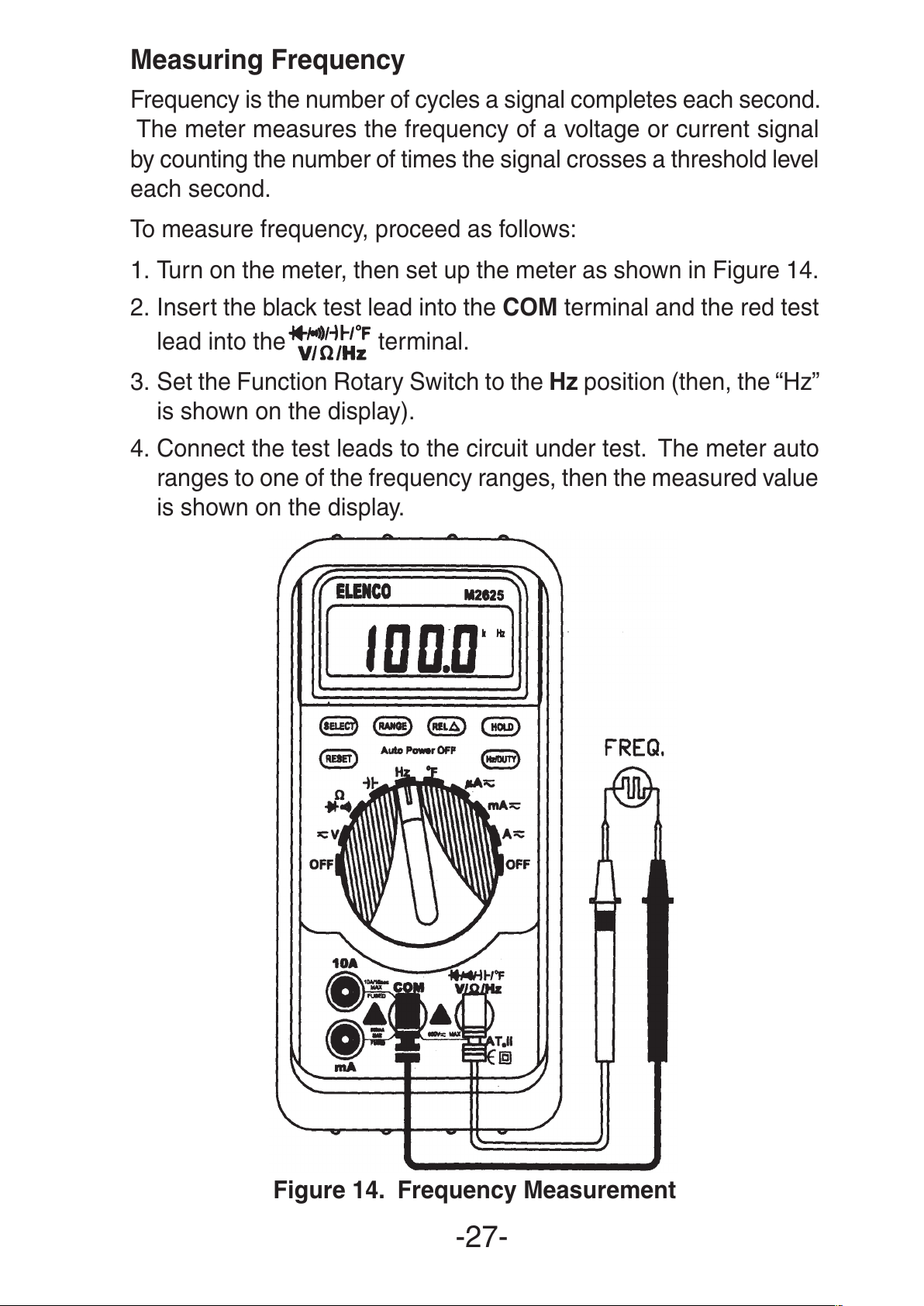
Measuring Frequency
Frequency is the number of cycles a signal completes each second.
The meter measures the frequency of a voltage or current signal
by counting the number of times the signal crosses a threshold level
each second.
To measure frequency, proceed as follows:
1. Turn on the meter, then set up the meter as shown in Figure 14.
2. Insert the black test lead into the COM terminal and the red test
lead into the terminal.
3. Set the Function Rotary Switch to the Hz position (then, the “Hz”
is shown on the display).
4. Connect the test leads to the circuit under test. The meter auto
ranges to one of the frequency ranges, then the measured value
is shown on the display.
Figure 14. Frequency Measurement
-27-
All manuals and user guides at all-guides.com
Page 28

Measuring Duty Cycle
Duty cycle (or duty factor) is the percentage of time a signal is
above or below a trigger level during one cycle (Figure 16).
To measure duty cycle, proceed as follows:
1. Turn on the meter, then set up the meter as shown in Figure 15.
2. Insert the black test lead into the COM terminal and the red test
lead into the terminal.
3. Set the Function Rotary Switch to the Hz position. Then press
Hz/DUTY once to select DUTY Cycle measurement (then, a “%”
symbol is indicated on the display).
4. Connect the test leads to the circuit under test. The measured
value is shown on the display.
Figure 15. Duty Cycle Measurement
-28-
All manuals and user guides at all-guides.com
Page 29

Figure 16. Duty Cycle Measurement
Measuring Temperature
Warning
To avoid the potential of fire or electrical shock, do not
connect the thermocouples to electrically live circuits.
To measure temperature, proceed as follows:
1. Turn on the meter, then set up the meter as shown in Figure 17.
2. Set the Function Rotary Switch to the
O
F position (then, the
“AUTO” and “OF” symbols are indicated on the display).
3. Plug the positive leg (+) of the type K thermocouples into the
terminal and the negative leg (–) into the COM terminal
and read the value on the display. The range of the TP-03
thermocouples is –58
O
F~+752OF.
4. Opening the input will display the temperature at the meter
terminals.
-29-
!
All manuals and user guides at all-guides.com
Page 30

Figure 17. Temperature Measurement
-30-
All manuals and user guides at all-guides.com
Page 31

8. Maintenance
General Maintenance
Periodically wipe the case with a damp cloth and mild detergent.
Do not use abrasives or solvents. Dirt or moisture in the terminals
can affect readings. Clean the terminals as follows:
1. Turn the meter off and remove all test leads.
2. Shake out any dirt that may be in the terminals.
3. Soak a new swab with alcohol. Work the swab around each
terminal.
Replacing the Batteries
Replace the batteries with two “AA” batteries (R6P) or equivalent.
Warning
To avoid false readings, which could lead to possible
electric shock or personal injury, replace the batteries as
soon as the low battery indicator ( ) appears.
Replace the batteries as follows (refer to Figure 18):
1. Turn the Function Rotary Switch to the OFF position and remove
the test leads from the terminals.
2. Remove the battery door by using a screwdriver to turn the
battery door screw counterclockwise.
3. Replace the batteries. Secure the door by turning the screws
clockwise.
Figure 18. Battery Replacement
-31-
!
Screw
Battery: Two R6P
(AA) or equivalent
+
All manuals and user guides at all-guides.com
all-guides.com
Page 32
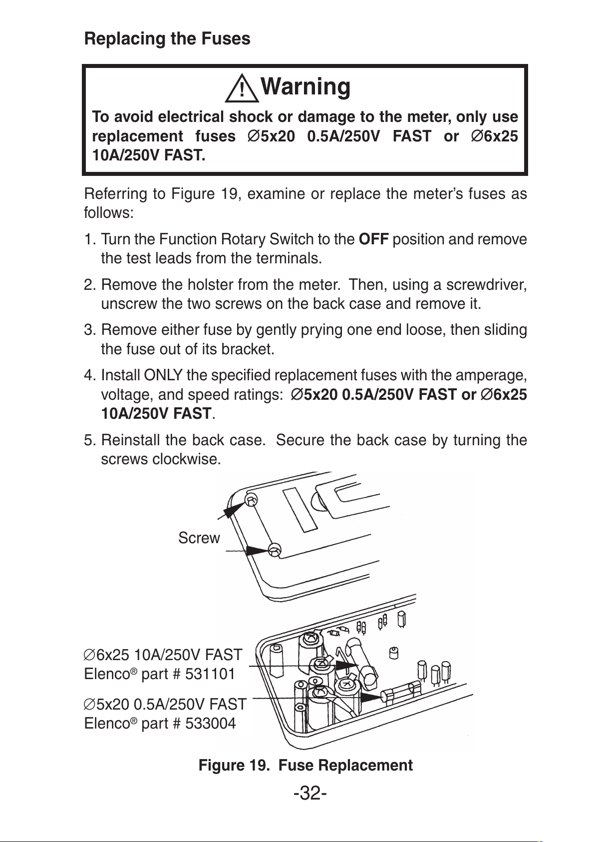
Replacing the Fuses
Warning
To avoid electrical shock or damage to the meter, only use
replacement fuses
∅∅
5x20 0.5A/250V FAST or
∅∅
6x25
10A/250V FAST.
Referring to Figure 19, examine or replace the meter’s fuses as
follows:
1. Turn the Function Rotary Switch to the OFF position and remove
the test leads from the terminals.
2. Remove the holster from the meter. Then, using a screwdriver,
unscrew the two screws on the back case and remove it.
3. Remove either fuse by gently prying one end loose, then sliding
the fuse out of its bracket.
4. Install ONLY the specified replacement fuses with the amperage,
voltage, and speed ratings:
∅∅
5x20 0.5A/250V FAST or ∅∅6x25
10A/250V FAST.
5. Reinstall the back case. Secure the back case by turning the
screws clockwise.
Figure 19. Fuse Replacement
-32-
!
Screw
∅6x25 10A/250V FAST
Elenco
®
part # 531101
∅5x20 0.5A/250V FAST
Elenco
®
part # 533004
All manuals and user guides at all-guides.com
Page 33
9. General Specifications
Display: 3¾ digit LCD with a maximum reading of 3999.
Range Control: Auto range or manual range control.
Polarity: Automatic negative polarity indication.
Zero Adjustment: Automatic
Overrange Indication: Only the “OL” display.
Low Battery: The symbol “ ” is displayed when the battery
voltage is below approximately 2.4V.
Auto Power Off: 30 minutes after stopping the switch or no key-
input, the meter automatically enters the power off mode.
Safety Standards: EMC/LVD. The meter is up to the standards
of IEC1010 pollution degree 2; overvoltage category II (double
insulation).
Operating Environment: Temperature 32
O
- 104OF (0Oto 40OC),
humidity <80% RH.
Storage Environment: Temperature –4
O
- 140OF (–20Oto 60OC),
humidity <85% RH.
Power: Two 1.5V “AA” batteries.
Dimensions: 6 3/32”/155mm (H) x 2 15/16”/75mm (W) x 1 5/16”/
33mm (D)
Weight: Approx. 9.2oz./260g. (including battery and holster)
Detailed Accuracy Specifications
Accuracies are ± (% of reading + number in last digit) at 73OF
±41OF/23OC ±5OC, <75% RH.
The detailed accuracy specifications are shown in Tables 7 to 18.
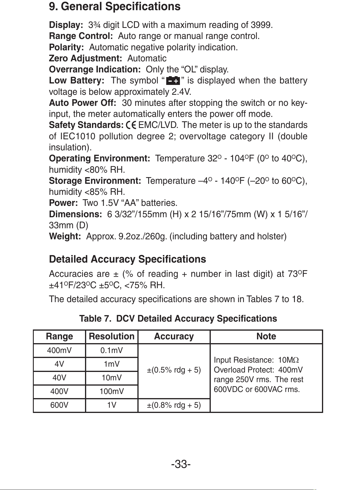
Table 7. DCV Detailed Accuracy Specifications
-33-
+
Range Resolution Accuracy Note
400mV 0.1mV
±(0.5% rdg + 5)
Input Resistance: 10MΩ
Overload Protect: 400mV
range 250V rms. The rest
600VDC or 600VAC rms.
4V 1mV
40V 10mV
400V 100mV
600V 1V ±(0.8% rdg + 5)
All manuals and user guides at all-guides.com
Page 34
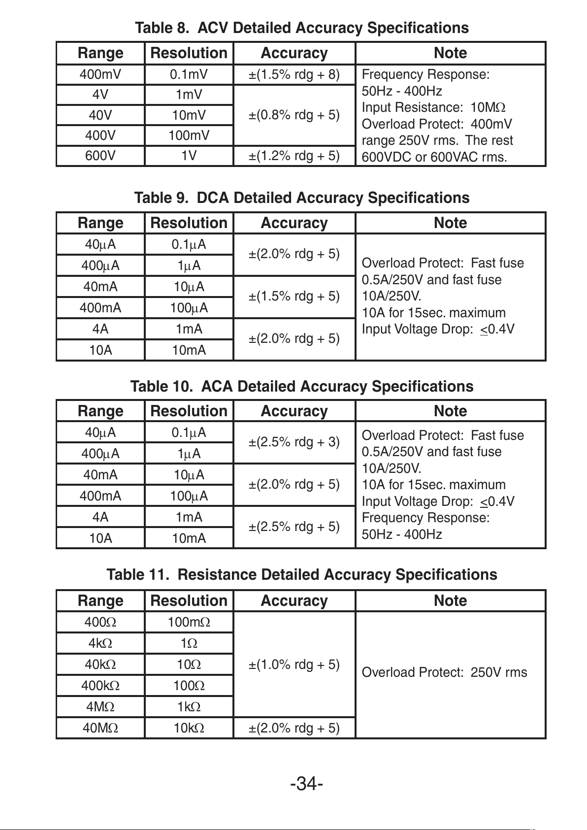
Table 8. ACV Detailed Accuracy Specifications
Table 9. DCA Detailed Accuracy Specifications
Table 10. ACA Detailed Accuracy Specifications
Table 11. Resistance Detailed Accuracy Specifications
-34-
Range Resolution Accuracy Note
400mV 0.1mV ±(1.5% rdg + 8) Frequency Response:
50Hz - 400Hz
Input Resistance: 10MΩ
Overload Protect: 400mV
range 250V rms. The rest
600VDC or 600VAC rms.
4V 1mV
±(0.8% rdg + 5)
40V 10mV
400V 100mV
600V 1V ±(1.2% rdg + 5)
Range Resolution Accuracy Note
40µA 0.1µA
±(2.0% rdg + 5)
Overload Protect: Fast fuse
0.5A/250V and fast fuse
10A/250V.
10A for 15sec. maximum
Input Voltage Drop: <0.4V
400µA 1µA
40mA 10µA
±(1.5% rdg + 5)
400mA 100µA
4A 1mA
±(2.0% rdg + 5)
10A 10mA
Range Resolution Accuracy Note
40µA 0.1µA
±(2.5% rdg + 3)
Overload Protect: Fast fuse
0.5A/250V and fast fuse
10A/250V.
10A for 15sec. maximum
Input Voltage Drop: <
0.4V
Frequency Response:
50Hz - 400Hz
400µA 1µA
40mA 10µA
±(2.0% rdg + 5)
400mA 100µA
4A 1mA
±(2.5% rdg + 5)
10A 10mA
Range Resolution Accuracy Note
400Ω 100mΩ
±(1.0% rdg + 5)
Overload Protect: 250V rms
4kΩ 1Ω
40kΩ 10Ω
400kΩ 100Ω
4MΩ 1kΩ
40MΩ 10kΩ ±(2.0% rdg + 5)
All manuals and user guides at all-guides.com
Page 35
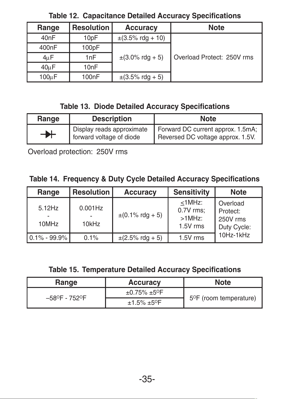
Table 12. Capacitance Detailed Accuracy Specifications
Table 13. Diode Detailed Accuracy Specifications
Overload protection: 250V rms
Table 14. Frequency & Duty Cycle Detailed Accuracy Specifications
Table 15. Temperature Detailed Accuracy Specifications
-35-
Range Resolution Accuracy Note
40nF 10pF ±(3.5% rdg + 10)
Overload Protect: 250V rms
400nF 100pF
±(3.0% rdg + 5)
4µF 1nF
40µF 10nF
100µF 100nF ±(3.5% rdg + 5)
Range Description Note
Display reads approximate
forward voltage of diode
Forward DC current approx. 1.5mA;
Reversed DC voltage approx. 1.5V.
Range Resolution Accuracy Sensitivity Note
5.12Hz
-
10MHz
0.001Hz
-
10kHz
±(0.1% rdg + 5)
<1MHz:
0.7V rms;
>1MHz:
1.5V rms
Overload
Protect:
250V rms
Duty Cycle:
10Hz-1kHz
0.1% - 99.9% 0.1% ±(2.5% rdg + 5) 1.5V rms
Range Accuracy Note
–58OF - 752OF
±0.75% ±5OF
5OF (room temperature)
±1.5% ±5OF
All manuals and user guides at all-guides.com
Page 36

Elenco®Electronics, Inc.
150 Carpenter Avenue
Wheeling, IL 60090
(847) 541-3800
Web site: www.elenco.com
e-mail: elenco@elenco.com
All manuals and user guides at all-guides.com
all-guides.com
 Loading...