

Page 1
SAFETY INFORMATION
The following safety information must be observed to insure
maximum personal safety during the operation of this meter:
1. Do not use the meter if the meter or test leads look damaged,
or if you suspect that the meter is not operating properly.
2. This meter is not recommended for high voltage industrial
use; for example, not for measurements of 440VAC or
600VAC industrial power mains. The unit is intended for
use with low energy circuits to 1000VDC or 750VAC or high
energy circuits to 250VAC or DC. Accidental misuse by
connection across a high voltage, high energy power source
when the meter is set up for mA measurement may be very
hazardous.
3. Turn off power to the circuit under test before cutting,
unsoldering, or breaking the circuit. Small amounts of
current can be dangerous.
4. Use caution when working above 60VDC or 30VAC rms.
Such voltages pose a shock hazard.
5. When using the probes, keep your fingers behind the finger
guards on the probes.
6. Measuring voltage which exceeds the limits of the
multimeter may damage the meter and expose the operator
to a shock hazard. Always recognize the meter voltage
limits as stated on the front of the meter.
SPECIFICATIONS
Display: 3 3/4 digit liquid crystal display (LCD) with a
maximum reading of 3999.
Polarity: Automatic, positive implied, negative polarity
indication.
Overrange: (OL) or (–OL) is displayed.
Zero: Automatic.
Low Battery Indication: The “ ” is displayed when the
battery voltage drops below the
operating level.
Measurement Rate: 2.5 times per second, nominal.
Operating Environment: 0
O
C to 50OC at <70% relative
humidity.
Storage Temperature: –20
O
C to 60OC, 0 to 80% R.H. with
battery removed from meter.
Accuracy: Stated accuracy at 23
O
C +5OC, <75% relative
humidity.
Power: Single standard 9-volt battery, NEDA 1604, JIS 006P,
IEC 6F22.
Battery Life: 150 hours typical with carbon-zinc.
Dimensions: 200mm (H) x 90mm (W) x 40mm (D).
Weight: Approx. 14 oz. (400g.) including battery.
Accessories: One pair test leads, one spare fuse (installed), 9V
battery (installed) and operating instructions.
+
DC VOLTS
Ranges: 400mV, 4V, 40V, 400V, 1000V
Resolution: 100mV
Accuracy: +
(0.5% rdg + 1 dgt)
Input Impedance: 10MW
Overload Protection: 1000VDC or 750VAC rms
AC VOLTS (50Hz - 500Hz)
Ranges: 400mV, 4V, 40V, 400V, 750V
Resolution: 100mV
Accuracy: +
(1.5% rdg + 4 dgts) on 400mV to 400V ranges
+
(2.0% rdg + 4 dgts) on 750V ranges
Input Impedance: 10MW
Overload Protection: 1000VDC or 750VAC rms
DC CURRENT
Ranges: 40mA, 400mA, 10A
Accuracy: +
(1.5% rdg + 1 dgt) on mA range
+(3.0% rdg + 1 dgt) on 10A range
Input Protection: 0.5A / 250V fast blow fuse
10A / 600V fast blow ceramic fuse
AC CURRENT (50Hz - 500Hz)
Ranges: 40mA, 400mA, 10A
Accuracy: +
(2.0% rdg + 4 dgts) on mA range
+
(3.5% rdg + 4 dgts) on 10A range
Input Protection: 0.5A / 250V fast blow fuse
10A / 600V fast blow ceramic fuse
RESISTANCE
Ranges: 400W,4kW, 40kW, 400kW,4MW, 40MW, 4000MW
Accuracy: +
(1.0% rdg + 4 dgts) on 400W range
+
(0.8% rdg + 2 dgts) on 4kW to 4MW ranges
+
(3.0% rdg + 4 dgts) on 40MW range
+[(5.0% rdg + 10 dgts) + 10 dgts] on 4000MW range
Open Circuit Volts: 0.6VDC (3.0VDC on 400Wand
4000M
W
ranges)
Overload Protection: 500VDC or AC rms
CONTINUITY
Audible Indication: Less than 40W +20W
Overload Protection: 500VDC or AC rms
DIODE TEST
Test Current: 1.0mA +0.6mA
Accuracy: +
(3.0% rdg + 3dgt)
Open Circuit Volts: 3.0VDC typical
Overload Protection: 500VDC or AC rms
CAPACITANCE
Ranges: 4nF, 40nF, 400nF, 4mF, 200mF
Accuracy: +
(5.0% rdg + 10dgts) on all ranges
+(8.0% rdg + 10dgts) above 100mF
Test Frequency: 200Hz
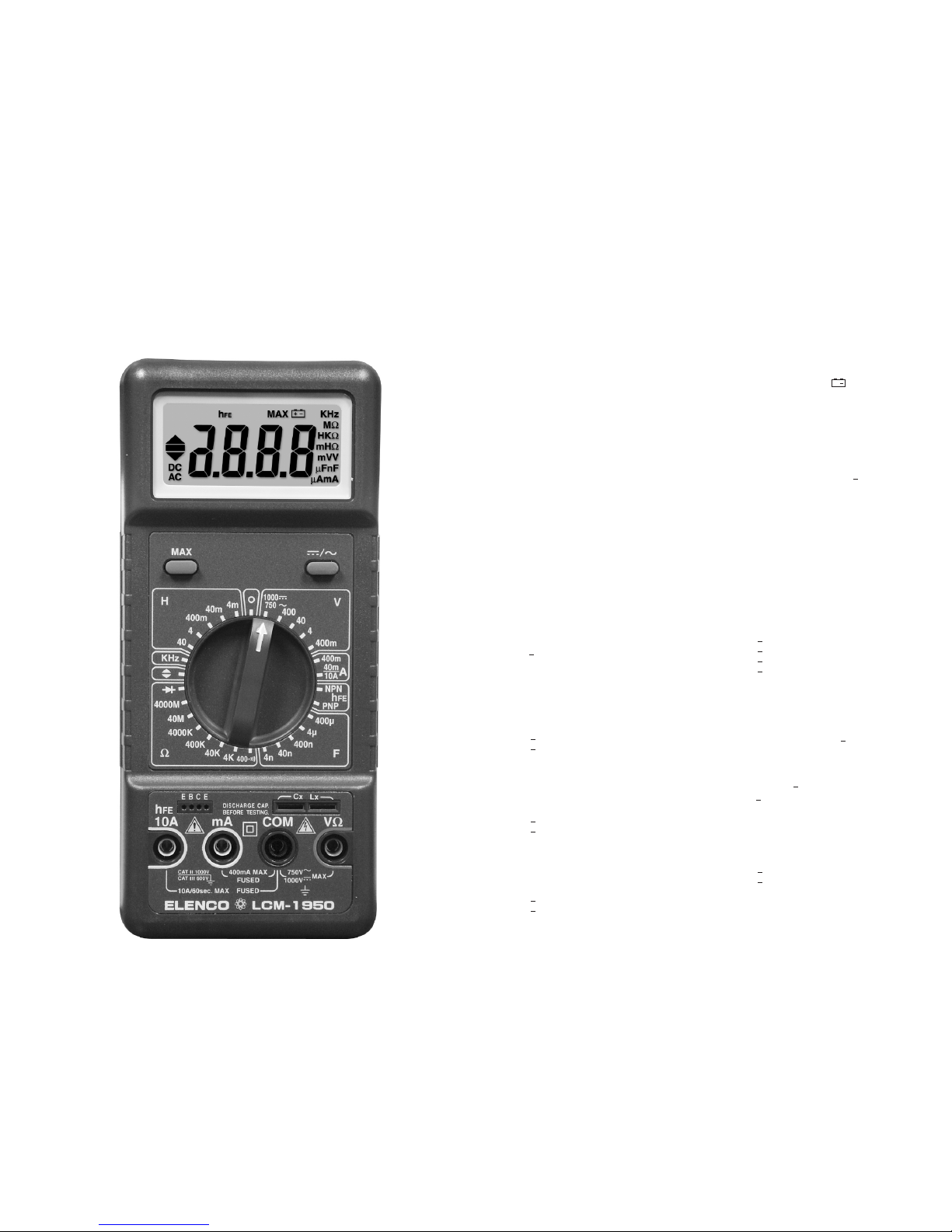
OPERATING INSTRUCTIONS
ELENCO LCM-1950
DIGITAL MULTIMETER
Page 2

INDUCTANCE
Ranges: 4mH, 40mH, 400mH, 4H, 40H
Accuracy: +
(5.0% rdg + 20 dgts) on 4mH
+
(5.0% rdg + 10 dgts) on other ranges
Test Frequency: 200Hz
FREQUENCY (Autoranging)
Ranges: 4kHz, 40kHz, 400kHz, 1000kHz
Accuracy: +
(0.5% rdg + 1 dgt) on all ranges
Sensitivity: 0.2V rms min.
Overload Protection: 500VDC or AC rms
LOGIC TEST
Threshold: Logic Hi (2.8 +0.8V)
Logic Lo (0.8 +0.5V)
Indication: 40 msec beep at logic low
Frequency Response: 20MHz
Detectable Pulse Width: 25nS.
Pulse Limits: >30% & <70% duty
Overload Protection: 500VDC or AC rms
TRANSISTOR hFE
Ranges: 0 - 1000
Base Current: 10mADC approx. (Vce = 3.3VDC)
OPERATION
Before taking any measurements, read the Safety Information
Section. Always examine the instrument for damage,
contamination (excessive dirt, grease, etc.) and defects.
Examine the test leads for cracked or frayed insulation. If any
abnormal conditions exist, do not attempt to make any
measurements.
Max. Hold Feature
Press “MAX” to toggle in and out of the Maximum Hold mode
(holding the highest reading). In the MAX mode, the MAX
annunciator is displayed and maximum reading is stored in
display register. If the new reading is higher than the reading
being displayed, the higher reading is transferred to the display
register. A “higher” reading is defined as the reading with the
higher absolute value.
The MAX hold function is also available in the frequency count
mode. The counter autoranging feature is disabled when the
MAX hold function is selected.
Voltage Measurements
1. Connect the red test lead to the “VW” jack and the black test
lead to the “COM” jack.
2. Set the Function/Range switch to the desired range and press
the “
/~
” switch to toggle between the desired voltage type.
If the magnitude of the voltage is not known, set the switch
to the highest range and reduce until a satisfactory reading is
obtained.
3. Connect the test leads to the device or circuit being
measured.
4. For DC, a (–) sign is displayed for negative polarity; positive
polarity is implied.
Current Measurements
1.
Set the Function/Range switch to the desired current range and
press the “ /~” selector switch to the desired current type.
2. For current measurements less than 400mA, connect the red
test lead to the “mA” jack and the black test lead to the
“COM” jack.
3. For current measurements over 400mA or greater, connect
the red test lead to the “10A” jack and the black test lead to
the “COM” jack.
4. Remove power from the circuit under test and open the
normal circuit path where the measurement is to be taken.
Connect the meter in series with the circuit.
Resistance and Continuity Measurements
1. Set the Function/Range switch to the desired resistance
range or continuity position.
2. Remove power from the equipment under test.
3. Connect the red test lead to the “VW” jack and the black test
lead to the “COM” jack.
4. Touch the probes to the test points. In ohms, the value
indicated in the display is the measured value of resistance.
In continuity test, the beeper sounds continuously, if the
resistance is less than 100W.
Transistor Gain Measurements
1. Set the Function/Range switch to the desired hFE range (PNP
or NPN type transistor).
2. Never apply an external voltage to the h
FE socket. Damage
to the meter may result.
3. Plug the transistor directly into the h
FE socket. The sockets
are labeled E, B, and C for emitter, base and collector.
4. Read the transistor h
FE (DC gain) directly from the display.
Capacitance & Inductance Measurements
1. Set the Function/Range switch to the desired Cx
(capacitance) or Lx (inductance) range.
2. Never apply an external voltage to the Cx/Lx sockets.
Damage to the meter may result.
3. Insert the capacitor or inductance leads directly into the
Cx/Lx sockets.
4. Read the capacitance or inductance directly from the display.
Frequency Measurements
1.
Set the Function/Range switch to the KHz position.
2. Connect the red test lead to the “VW” jack and the black test
lead to the “COM” jack.
3. Connect the test leads to the point of measurement and read
the frequency from the display.
Logic Measurements
1. Set the Function/Range switch to the LOGIC position.
2. Connect the red test lead to the “VW” jack and the black test
lead to the “COM” jack.
3. Connect the red test lead to the test point and the black lead
to the common buss of the logic circuit.
4. A “ ” on the display indicates TTL logic high and a “ ”
indicates a TTL logic low. Both indicators are on when the
point of measurement is toggling high and low.
Diode Tests
1. Connect the red test lead to the “VW” jack and the black test
lead to the “COM” jack.
2. Set the Function/Range switch to the “ ” position.
3. Turn off the power to the circuit under test.
4. Touch the probes to the diode. A forward-voltage drop is
about 0.6V (typical for a silicon diode).
5. Reverse the probes. If the diode is good, the display will be
between 2.800V and 3.200V. If the diode is shorted, “.000”
of another number is displayed.
6. If the diode is open, the display will be between 2.800V and
3.200V in both directions.
7. If the junction is measured in a circuit and a low reading is
obtained with both lead connections, the junction may be
shunted by a resistance of less than 1kW. In this case, the
diode must be disconnected from the circuit for accurate
testing.
MAINTENANCE
Battery Replacement
Power is supplied by a 9 volt “transistor” battery (NEDA 1604,
IEC 6F22). The “ ” appears on the LCD display when
replacement is needed. To replace the battery, remove the two
screws from the back of the meter and lift off the battery cover.
Remove the battery from the battery snap.
Fuse Replacement
If no current measurements are possible, check for a blown
overload protection fuse. There are two fuses; F1 for the “mA”
jack and F2 for the “10A” jack. For access to fuses, remove the
two screws from the back of the meter and lift off the battery
cover. Replace F1 only with the original type 0.5A/250V, fast
acting fuse. Replace F2 only with the original type 10A/600V,
fast acting ceramic fuse.
WARNING
Remove test leads before changing battery or
performing any servicing.
+
 Loading...