

Elenco Electronics K-44 Assembly And Instruction Manual
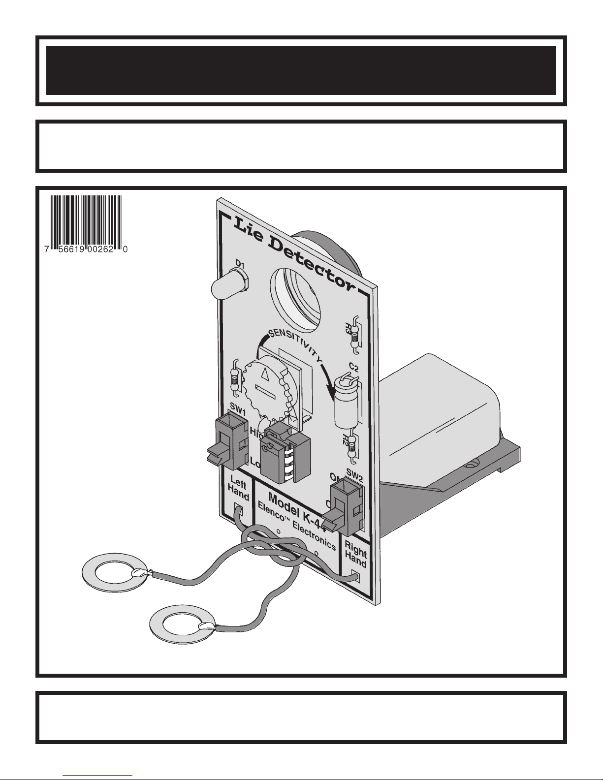
LIE DETECTOR KIT
MODEL K-44
Assembly and Instruction Manual
Elenco
Copyright © 2003 ElencoTMElectronics, Inc. 753116
TM
Electronics, Inc.
PARTS LIST
If you are a student, and any parts are missing or damaged, please see instructor or bookstore.
If you purchased this Lie Detector kit from a distributor, catalog, etc., please contact Elenco™ Electronics
address/phone/e-mail is at the back of this manual) for additional assistance, if needed.
RESISTORS
Qty. Symbol Value Color Code Part #
1 R3 1kW 5% 1/4W brown-black-red-gold 141000
1 R2 100kW 5% 1/4W brown-black-yellow-gold 161000
1 R1 1MW 5% 1/4W brown-black-green-gold 171000
1 VR1 900kW Potentiometer 191695
CAPACITORS
Qty. Symbol Value Description Part #
1 C1 .022mF (203) Disc 242010
1 C2 47mF Electrolytic 274744
SEMICONDUCTORS
Qty. Symbol Value Description Part #
1 U1 LM555 /LM1455 IC (Integrated Circuit) 330555
1 D1 LED (Light Emitting Diode) 350002
MISCELLANEOUS
Qty. Symbol Description Part #
1 PC Board 518044
1 Speaker 64W 520813
2 SW1, 2 Slide Switch 541102
24” Solder 63/37 551124
1 Battery Holder 590096
2 Washer 8mm x 14mm 645101
1 Socket 8-pin 664008
1 Foam Tape 740020
1 Speaker Pad 780125
1 Wire 22 AWG Stranded 814001
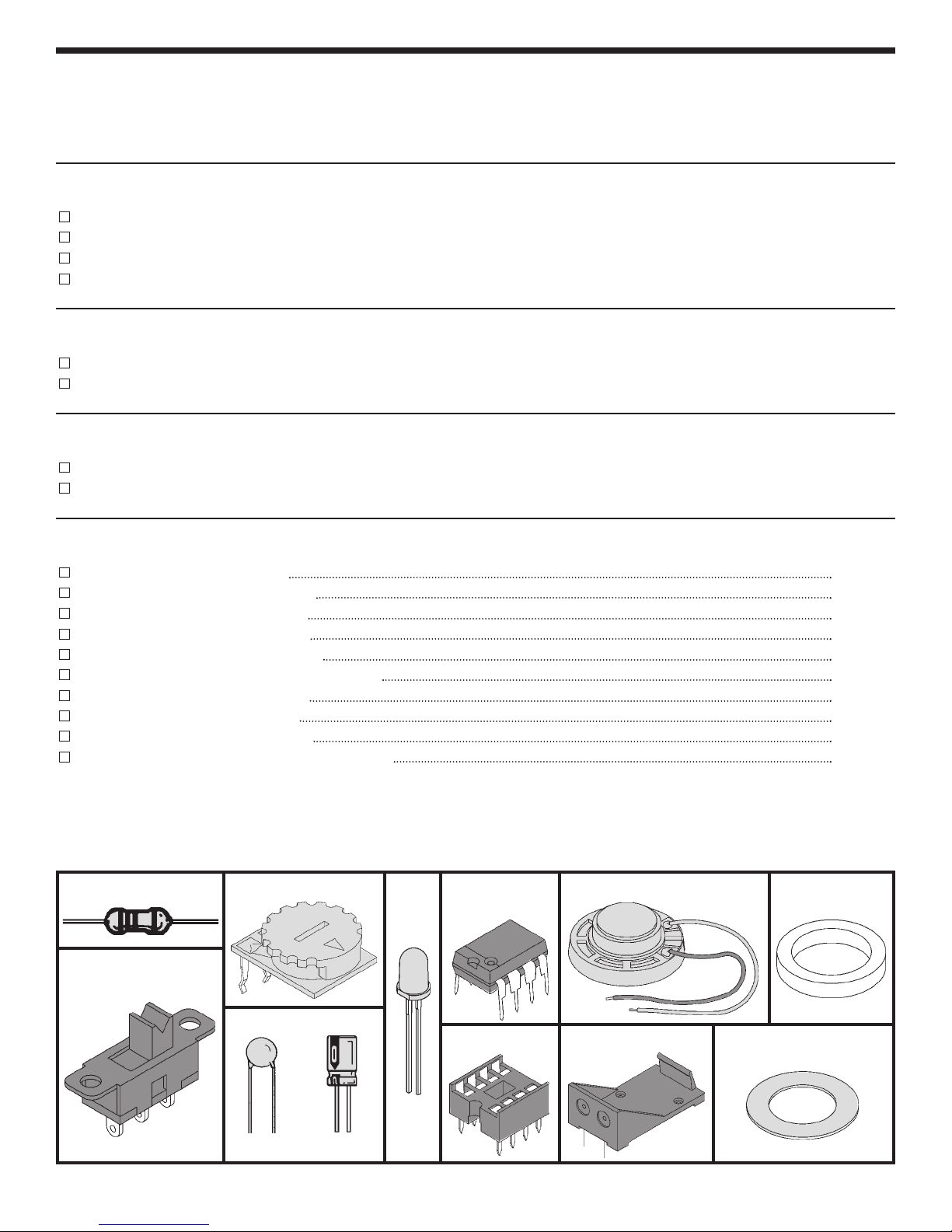
PARTS IDENTIFICATION
Resistor
Switch
Potentiometer
LED Speaker 64
Integrated
Circuit
W
W
Speaker Pad
Capacitor
(–) (+)
Discap Electrolytic
IC Socket 8-pin
-1-
Battery Holder
Washer
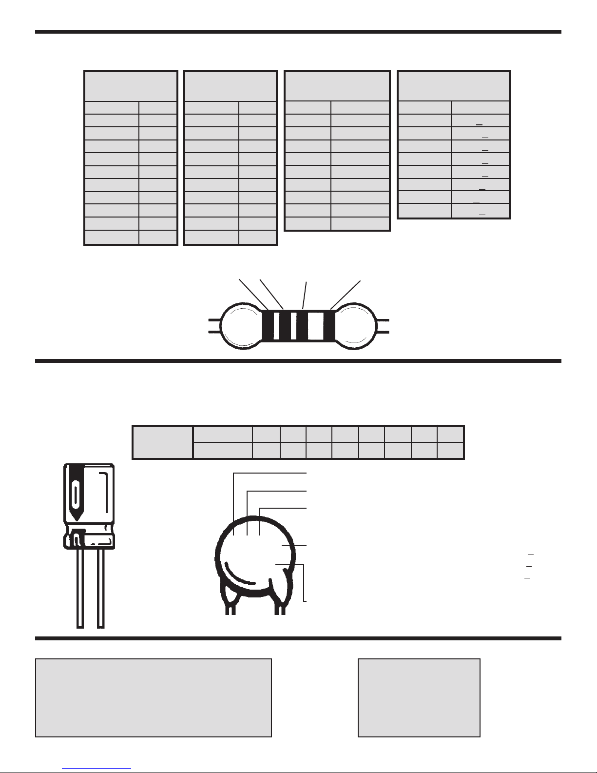
IDENTIFYING RESISTOR VALUES
Use the following information as a guide in properly identifying the value of resistors.
BAND 1
1st Digit
Color Digit
Black 0
Brown 1
Red 2
Orange 3
Yellow 4
Green 5
Blue 6
Violet 7
Gray 8
White 9
BAND 2
2nd Digit
Color Digit
Black 0
Brown 1
Red 2
Orange 3
Yellow 4
Green 5
Blue 6
Violet 7
Gray 8
White 9
2 Multiplier Tolerance
1
Multiplier
Color Multiplier
Black 1
Brown 10
Red 100
Orange 1,000
Yellow 10,000
Green 100,000
Blue 1,000,000
Silver 0.01
Gold 0.1
BANDS
Resistance
Tolerance
Color Tolerance
Silver +10%
Gold +
Brown +1%
Red +2%
Orange +
Green +.5%
Blue +.25%
Violet +
5%
3%
.1%
IDENTIFYING CAPACITOR VALUES
Capacitors will be identified by their capacitance value in pF (picofarads), nF (nanofarads), or mF (microfarads). Most
capacitors will have their actual value printed on them. Some capacitors may have their value printed in the following
manner. The maximum operating voltage may also be printed on the capacitor.
Multiplier
10mF 16V
For the No.01234589
Multiply By 1 10 100 1k 10k 100k .01 0.1
Note: The letter “R” may be used at times
to signify a decimal point; as in 3R3 = 3.3
The letter M indicates a tolerance of +
The letter K indicates a tolerance of +10%
The letter J indicates a tolerance of +5%
103K
100V
First Digit
Second Digit
Multiplier
Tolerance
Maximum Working Voltage
20%
The value is 10 x 1,000 = 10,000pF or .01mF 100V
METRIC UNITS AND CONVERSIONS
Abbreviation Means Multiply Unit By Or
p Pico .000000000001 10
n nano .000000001 10
m micro .000001 10
m milli .001 10
– unit 1 10
k kilo 1,000 10
M mega 1,000,000 10
-12
-9
-6
-3
0
3
6
-2-
1. 1,000 pico units = 1 nano unit
2. 1,000 nano units = 1 micro unit
3. 1,000 micro units= 1 milli unit
4. 1,000 milli units = 1 unit
5. 1,000 units = 1 kilo unit
6. 1,000 kilo units= 1 mega unit
 Loading...