

Page 1
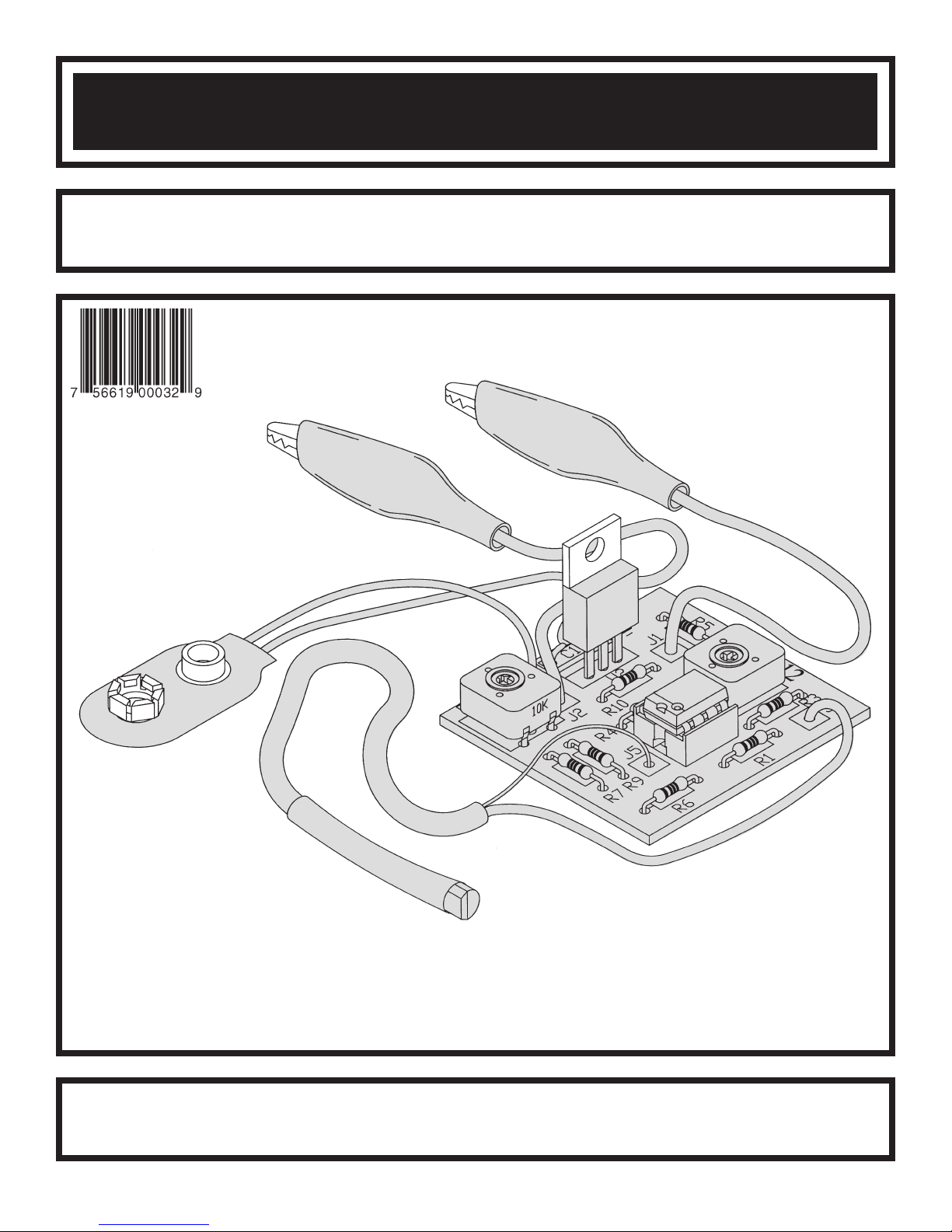
TEMPERATURE ADAPTER KIT
MODEL TA-12/K-40
Assembly and Instruction Manual
Elenco®Electronics, Inc.
ight © 2005, 1994 b
yr
Cop
t of this book shall be reproduced b
No par
y Elenco
®
Electronics
y means;
y an
, Inc.
electronic
ights reser
All r
, photocopying, or otherwise without written permission from the publisher.
ved. Revised 2005 REV-C 753125
Page 2
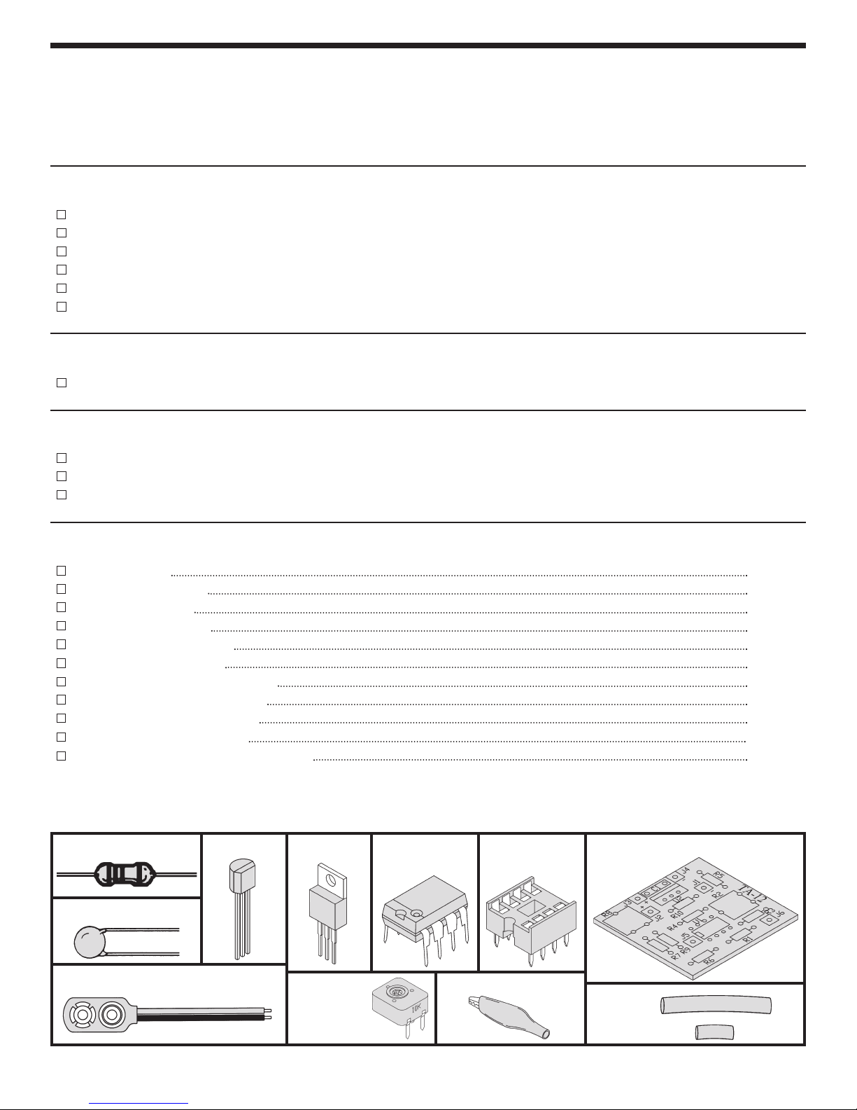
PARTS LIST
If you are a student, and any parts are missing or damaged, please see instructor or bookstore.
If you purchased this kit from a distributor, catalog, etc., please contact Elenco
mail is at the back of this manual) for additional assistance, if needed. DO NOT contact your place of purchase
as they will not be able to help you.
RESISTORS
Qty. Symbol Description Color Code Part #
2 R5, R6 1kΩ 5% 1/4W brown-black-red-gold 141000
1 R7 3.3kΩ 5% 1/4W orange-orange-red-gold 143300
2 R1, R10 3.9kΩ 5% 1/4W orange-white-red-gold 143900
2 R4, R9 10kΩ 5% 1/4W brown-black-orange-gold 151000
1 R3 47kΩ 5% 1/4W yellow-violet-orange-gold 154700
2 R2, R8 10kΩ Trim Pot 191510
CAPACITORS
Qty. Symbol Description Part #
1 C1 .01µF, 50V (103) 241031
SEMICONDUCTORS
Qty. Symbol Description Part #
1 Q1 2N3904 NPN Transistor 323904
1 U1 LM1458N Op-Amp Integ
1 U2 MC7805 5V Regulator 337805
rated Circuit (IC) 331458
®
Electronics (address/phone/e-
MISCELLANEOUS
. Description Part #
Qty
1 PC Board
518040
1 Solder Roll 24” 551124
1 Battery Snap
1 IC Soc
ket 8-pin 664008
590098
1 Alligator Clip Black 680001
1 Alligator Clip Red 680002
1 Solid Black Wire 22ga. 6” 814120
1 Solid Red Wire 22ga. 6” 814220
Cable 2 Conductor 24” 876090
1
1 #7 Shrink Tubing 1/2” 890050
1 3/16” Dia. Shrink Tubing 1 1/2” 890120
PARTS IDENTIFICATION
Resistor Transistor
Capacitor
Regulator
Integrated
Circuit
IC Socket
8-pin
PC Board
Battery Snap
Trim Pot
-1-
Alligator Clip
Shrink
Tubing
3/16”
#7
Page 3
INTRODUCTION
The TA-12/K-40 Temperature Adapter Kit is used in
c
onjunction with a digital multimeter to read
temperature. The Temperature Adapter consists of
THEORY OF OPERATION
VOLTAGE REGULATOR
The MC7805 (U2) is the voltage regulator which is
used to supply a constant voltage of about 5V to the
circuit.
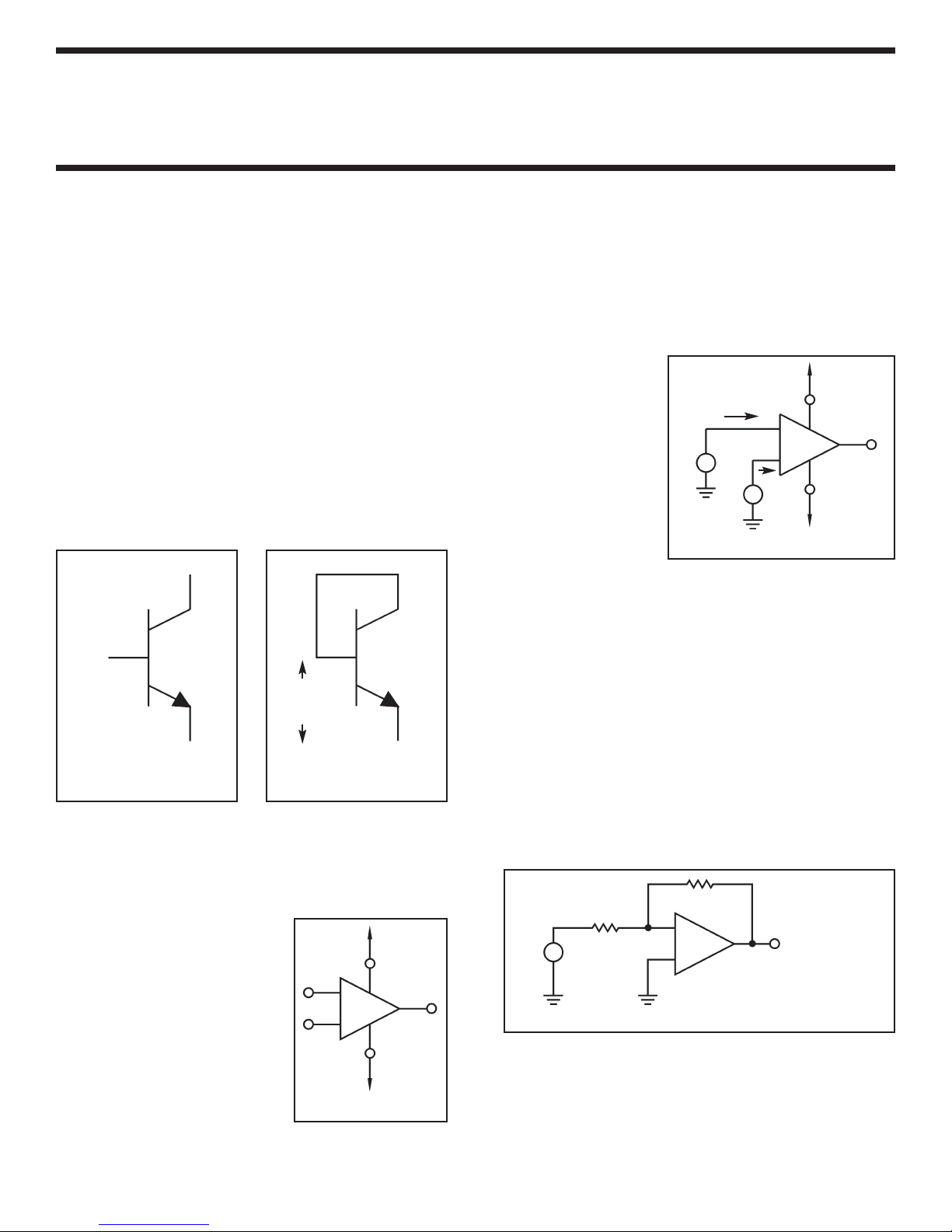
TEMPERATURE SENSOR
The Temperature Sensor is an NPN transistor
(2N3904). The NPN transistor has three
terminals: the collector, base, and emitter as
shown in Figure 1. When the collector and base of
this transistor are shorted together as shown in
Figure 2, they behave exactly like a diode, which is
a temperature-sensitive device. At a constant
current, the voltage across the base to emitter
junction decreases by approximately 1mV for
every 1
O
F increase in temperature.
Collector
three main sections: • Voltage Regulator
•
Temperature Sensor
• Op-Amp
The op-amp senses the difference between the
voltage signals applied at its two terminals (that is,
the quantity v2 - v1), multiplies this by the open loop
gain A, and causes the resulting voltage A(v2 - v1)
to appear at output terminal 3 as shown in Figure 4.
In an ideal op-amp,
V+
the input impedance
is infinite, the output
impedance is zero
and the open loop
gain A is very large
and ideally infinite. In
, the open
actice
pr
loop gain is usually
greater than 100,000.
V1
i1 = 0
+
–
i2 = 0
+
V2
–
Figure 4
1
2
–
+
4
A(V2 - V1)
5
V–
3
Base
2N3904 NPN
Transistor
Base and
Emitter
Junction
Emitter
Figure 1
2N3904 NPN
Transistor
Figure 2
OP-AMP
The op-amp (LM1458) has tw
one output terminal. Figure 3 shows the op-amp
symbol. Terminals 1 and 2 are the input terminals,
and terminal 3 is the output
terminal. Many op-amps use
o DC po
tw
o terminals, 4 and 5, are
tw
connected to a positiv
wer supplies. The
e voltage
(V+) and negative voltage
(V–), respectively. The TA12/K-40 uses a single supply
with g
round tied to the
input.
o input terminals and
V+
1
2
V–
4
–
+
5
V–
Figure 3
3
In order to control the gain of our circuit we use
feedback to close the loop around the op-amp as
shown in Figure 5.
This circuit consists of an opamp and two resistors R1 and R2. Resistor R2 is
connected from the output terminal of the op-amp,
minal 3, back to the negative input ter
ter
minal,
terminal 1. We speak of R2 as applying negative
feedback; if R2 were connected between terminals
3 and 2, we would call this
positive feedback
. Note
that R2 closes the loop from the output terminal
k around to the input terminal of the op-amp. In
bac
this circuit, the closed loop gain (G) of the op-amp,
from the input Vi to the output terminal, depends on
the ratio of R2 to R1.
R2
1
+
Vi
R1
–
–
2
+
3
+
V0 = –(R2/R1) Vi
–
or
V0 = – GVi
Figure 5
For example, if R2 = 100 and R1 = 10, the gain G =
R2/R1 = 100/10 = 10. Thus, the output voltage V0
at terminal 3 would be equal to –10(Vi). The (–) sign
indicates that the output and input v
.
opposite polar
ity
oltages are of
-2-
Page 4

CONSTRUCTION
Introduction
The most important factor in assembling your TA-12/K-40 Temperature Adapter Kit is good soldering techniques.
Using the proper soldering iron is of prime importance. A small pencil type soldering iron of 25 - 40 watts is
recommended. The tip of the iron must be kept clean at all times and well tinned.
Safety Procedures
• Wear eye protection when soldering.
Locate soldering iron in an area where you do not have to go around it or reach over it.
•
• Do not hold solder in your mouth. Solder contains lead and is a toxic substance. Wash your hands
thoroughly after handling solder.
• Be sure that there is adequate ventilation present.
Assemble Components
In all of the following assembly steps, the components must be installed on the top side of the PC board unless
otherwise indicated. The top legend shows where each component goes. The leads pass through the
corresponding holes in the board and are soldered on the foil side.
Use only rosin core solder of 63/37 alloy.
Foil Side
DO NOT USE ACID CORE SOLDER!
What Good Soldering Looks Like
A good solder connection should be bright, shiny,
smooth, and uniformly flowed over all surfaces.
1. Solder all components from
the copper foil side only.
Push the soldering iron tip
against both the lead and
the circuit board foil.
2. Apply a small amount of
solder to the iron tip. This
allows the heat to leave the
iron and onto the f
Immediately apply solder to
the opposite side of the
connection, away from the
iron. Allow the heated
component and the circuit
oil to melt the solder.
f
Allow the solder to flo
3.
around the connection.
Then, remove the solder
and the iron and let the
connection cool.
solder should have flowed
smoothly and not lump
around the wire lead.
4.
Here is what a good solder
connection looks like.
oil.
The
Component Lead
Foil
Solder
Foil
w
Solder
F
oil
Soldering Iron
Circuit Board
Soldering Iron
Soldering Iron
Mount Part
Bend Leads to
Hold Part
Solder and
Cut Off Leads
Types of Poor Soldering Connections
1. Insufficient heat - the
solder will not flow onto the
lead as shown.
2. Insufficient solder - let the
solder flow over the
connection until it is
vered. Use just enough
co
solder to co
connection.
3. Excessive solder - could
make connections that you
did not intend to between
adjacent foil areas or
minals.
ter
4. Solder bridges - occur
when solder runs between
circuit paths and creates a
short circuit. This is usually
caused by using too much
solder. To correct this,
simply dr
iron across the solder
bridge as shown.
ag y
ver the
our solder
ing
Rosin
Soldering iron positioned
incorrectly.
Solder
Component Lead
Solder
Solder
Foil
ing Iron
Dr
Gap
ag
-3-
Page 5

ASSEMBLE COMPONENTS TO THE PC BOARD
R2 - 10kΩ Trim Pot
see Figure A)
(
R5 - 1kΩ 5% 1/4W Resistor
(brown-black-red-gold)
R10 - 3.9kΩ 5% 1/4W Resistor
(orange-white-red-gold)
C1 - .01µF, 50V (103) Discap
U2 - MC7805 5V Regulator
(see Figure B)
R4 - 10kΩ 5% 1/4W Resistor
(brown-black-orange-gold)
R8 - 10kΩ Trim Pot
(see Figure A)
Figure A
Insert the trim pot into the PC board
as shown. Solder and cut off excess
leads.
10kΩ Trim Pot
Figure B
Insert the regulator into the PC board
in the direction shown. Solder and cut
off excess leads.
MC7805
Regulator
R3 - 47kΩ 5% 1/4W Resistor
yellow-violet-orange-gold)
(
R1 - 3.9kΩ 5% 1/4W Resistor
(orange-white-red-gold)
U1 - IC Socket 8-pin
U1 - LM1458N Op-Amp IC
(see Figure C)
R6 - 1kΩ 5% 1/4W Resistor
(brown-black-red-gold)
R9 - 10kΩ 5% 1/4W Resistor
(brown-black-orange-gold)
R7 - 3.3kΩ 5% 1/4W Resistor
(orange-orange-red-gold)
Figure C
Insert the 8-pin IC socket into the PC
board in the direction shown. Solder
and cut off excess leads. Then, insert
the LM1458N op-amp IC into the
socket in the same direction shown.
PC Board
PC Board
LM1458N
Op-Amp IC
ket
IC Soc
8-pin
PC Board
-4-
Page 6

FINAL ASSEMBLY
Black
J3 - Battery Snap Red Wire
J4 - Battery Snap Black Wire
J2 - Black Multimeter Lead
(see Figure D)
J1 - Black Multimeter Lead
(see Figure D)
Red
6 - Large Sensor Wire
J
J5 - Small Sensor Wire
(see Figure E)
Figure D
Pull the boot off of the alligator clip (to remove boot, clip
the alligator clip onto a pencil, then pull off boot). Insert
the wire (red wire for red boot, black wire for black boot)
into the alligator clip as shown. Crimp the tabs over the
wire as shown and solder the wire to the clip. Cut off any
excess wire from the solder joint. Slide the boot back onto
the alligator clip.
Figure E
Prepare the ends of the 24” cable as shown in Step A
to the right. Very carefully strip off 1” of casing on
both ends of the cable to expose the two wires inside.
Then strip the insulation off of both ends of the
insulated wire to expose 1/4” of bare wire. On one
end, cut the bare wire so that it is 1/4”
Solder the 2N3904 tr
ansistor to the end of the cable
wire with the 1” bare wire as shown in Step B to the
ight. Slide the 1/2” section of #7 shrink tubing over
r
the bare wire
. Solder the bare wire to the base (B)
and collector (C) leads of the transistor. Slide the #7
tubing over the solder joint. Put your hot soldering
iron or heat gun close to the tubing (do not touch the
tubing). The heat from your iron or heat gun will
shrink the tubing into place. Solder the insulated
wire to the emitter (E) transistor lead.
Slide the 1 1/2” section of 3/16” shrink tubing over the
transistor to cover the exposed wires as shown in
Step C to the right. Shrink the tubing in place with
your iron or heat gun.
Solder the other end of the cable to the PC board.
The insulated wire goes to point J6 and the bare wire
to point J5.
long.
Insulated
Step A
1/4”
Wire
Step B
Step C
Boot
1”
Bare
Wire
1 1/2” Section of
Shrink Tubing
dia.
3/16”
Alligator Clip
¼” ¾”
0 1”
1/4”
½”
Casing
#7 Shrink
ubing
T
Crimp Tabs
1”
(E)
(B) & (C)
Solder
2N3904
ansistor
r
T
1/4”
-5-
Page 7

CALIBRATION
1
. Connect a 9V battery to the battery snap.
2. Connect the positive probe of your digital multimeter to point J1, and the negative probe to GND.
3. Adjust R2 for a reading of about 2.5 to 3V.
4. Then, connect the positive probe of the digital multimeter to J2 and the negative probe to J1.
5. Adjust R8 for the correct temperature reading on the digital multimeter. If you use the 2 volt range, you can
read the temperature to one tenth of a degree (that is, if the reading on the digital mulitmeter shows 0.733,
then you should read the temperature as 73.3
O
F).
COMPONENT CHECK
1. Recheck all of the values of the resistors, and make sure that they are placed in their exact location.
2. Be sure that the temperature sensor (2N3904) wire are soldered to their correct positions.
3. Be sure the notch of the op-amp (1458) is installed in the same direction as the marking on the PC board.
4. Be sure the regulator (7805) is mounted as instructed in the manual.
TROUBLESHOOTING
Contact Elenco®Electronics if you have any problems. DO NOT contact your place of purchase as they will not
be able to help you.
1. One of the most frequently occurring problems is poor solder connections. Tug slightly on all parts to make
sure that the
2. All solder connections should be shiny. Resolder any that are not.
3. Solder should flow into a smooth puddle rather than a round ball. Resolder any connection that has formed
into a ball.
4. Have any solder bridges formed? A solder bridge may occur if you accidentally touch an adjacent foil by
using too much solder or by dragging the soldering iron across adjacent foils. Break the bridge with your
soldering iron.
y are indeed soldered.
SCHEMATIC DIAGRAM
-6-
Page 8

QUIZ
Fill in the blanks and check your answers below.
1. The three main sections of the TA-12/K-40 are
________________, ________________, and
________________.
2. The output voltage of the LM7805 regulator is
_____ volts.
3. Name the three terminals of the transistor:
__________, __________, and __________.
4. The __________ and __________ leads of the
transistor are shorted together to make the
sensor.
5. At a constant current, the voltage across the base
to emitter junction decreases by approximately
______ f
or ever
y ______ increase in temper
ature.
6. The op-amp has ______ inputs terminals and
______ output terminal.
7. The TA-12/K-40 circuit uses __________
feedback to control the gain of the op-amp.
8. In the TA-12/K-40 circuit, a __________ supply is
used to power the op-amp.
9. In an ideal op-amp, the input impedance is
________, the output impedance is ________
and the open loop gain A is ideally ________.
10. You adjust trim pot ______ for the correct
temperature reading on the meter.
Elenco®Electronics, Inc.
150 Carpenter Avenue
Wheeling, IL 60090
(847) 541-3800
Website: www.elenco.com
e-mail: elenco@elenco.com
F; 6. two, one; 7. negative; 8. single; 9. infinite, zero, infinite; 10. R8
O
5. 1mV, 1
Answers: 1. voltage regulator, temperature sensor, op-amp; 2. five; 3. collector, base, emitter; 4. collector, base;
 Loading...