

Page 1
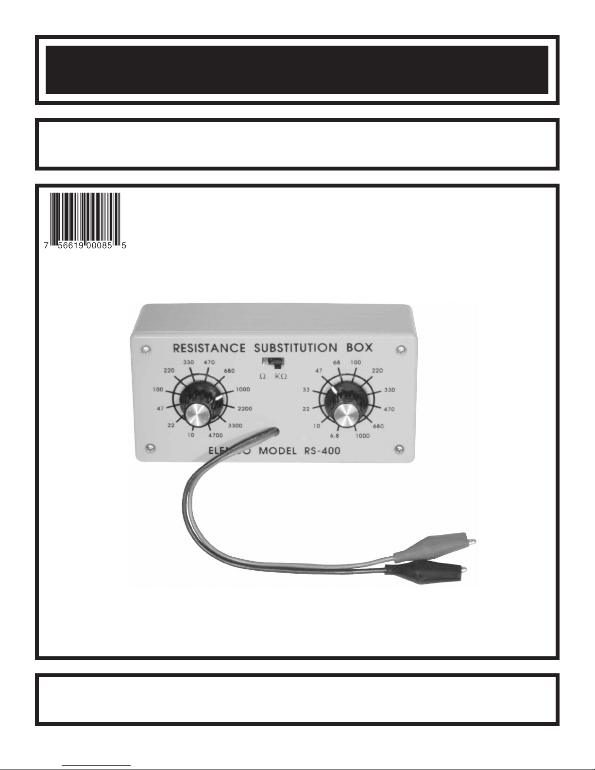
RESISTANCE SUBSTITUTION BOX
MODEL K-37
Assembly and Instruction Manual
Elenco®Electronics, Inc.
ight © 2004 b
yr
Cop
t of this book shall be reproduced b
No par
y Elenco
®
Electronics
y an
y means;
, Inc.
ights reser
All r
electronic
ved. 753400
, photocopying, or otherwise without written permission from the publisher.
Page 2
The Resistance Substitution Box is a convenient instrument in determining the desired resistance values in
circuits under design or test. The values selected for your resistance substitution box were determined to be
the most commonly used in modern solid-state circuits. The values are from 10W to 1,000kW (1 meg) in 24
steps. All resistors are 5% tolerance 1/2 watt.
PARTS LIST
If you are a student, and any parts are missing or damaged, please see instructor or bookstore.
If you purchased this kit from a distributor, catalog, etc., please contact Elenco®Electronics (address/phone/email is at the back of this manual) for additional assistance, if needed. DO NOT contact your place of purchase
as they will not be able to help you.
RESISTORS
Qty. Symbol Description Color Code Part #
1 R1 10W 5% 1/2W brown-black-black-gold 121001
1 R2 22W 5% 1/2W red-red-black-gold 122201
1 R3 47W 5% 1/2W yellow-violet-black-gold 124701
1 R4 100W 5% 1/2W brown-black-brown-gold 131001
1 R5 220W 5% 1/2W red-red-brown-gold 132201
1 R6 330W 5% 1/2W orange-orange-brown-gold 133301
1 R7 470W 5% 1/2W yellow-violet-brown-gold 134701
1 R8 680
1 R9 1k
1 R10
1 R11
1 R12 4.7kW 5% 1/2W yello
1 R13 6.8k
1 R14
1 R15
1 R16
1 R17 47kW 5% 1/2W yello
1 R18 68kW 5% 1/2W
1 R19 100k
1 R20 220k
1 R21
1 R22 470kW 5% 1/2W yellow-violet-yellow-gold 164701
1 R23 680kW 5% 1/2W blue-gray-yellow-gold 166801
R24 1M
1
W 5% 1/2W
W 5% 1/2W
2.2k
W 5% 1/2W
3.3kW 5% 1/2W or
W 5% 1/2W
10k
W 5% 1/2W
22k
W 5% 1/2W red-red-or
33kW 5% 1/2W or
W 5% 1/2W
W 5% 1/2W
330k
W 5% 1/2W or
W 5% 1/2W
blue-gray-brown-gold 136801
brown-blac
red-red-red-gold
ange-or
w-violet-red-gold
blue-gray-red-gold 146801
wn-blac
bro
ange-or
w-violet-or
blue-g
brown-blac
red-red-yellow-gold
ange-orange-y
brown-black-green-gold 171001
k-red-gold
ange-red-gold 143301
ange-gold 151001
k-or
ange-gold 152201
ange-orange-gold
ange-gold 154701
ange-gold 156801
ray-or
k-yello
w-gold
ellow-gold 163301
141001
142201
144701
153301
161001
162201
Qty. Description Part #
1 PC Board 517007
1 Switch SPDT PC Mount 541103
2 Switch 12 Position 542013
2 Knob 622009
1
4
2 Nut 9mm 644102
2 Washer 9mm x 15mm 645103
1 Alligator Clip Black 680001
1 Alligator Clip Red 680002
1
1
1 Solder 9ST4
Case with Co
Screw 4 x 1/2” Phil A 642465
Wire Blac
Wire Red Str
ver 62RS400
k Stranded 12” 814210
anded 12”
MISCELLANEOUS
814215
-1-
Page 3
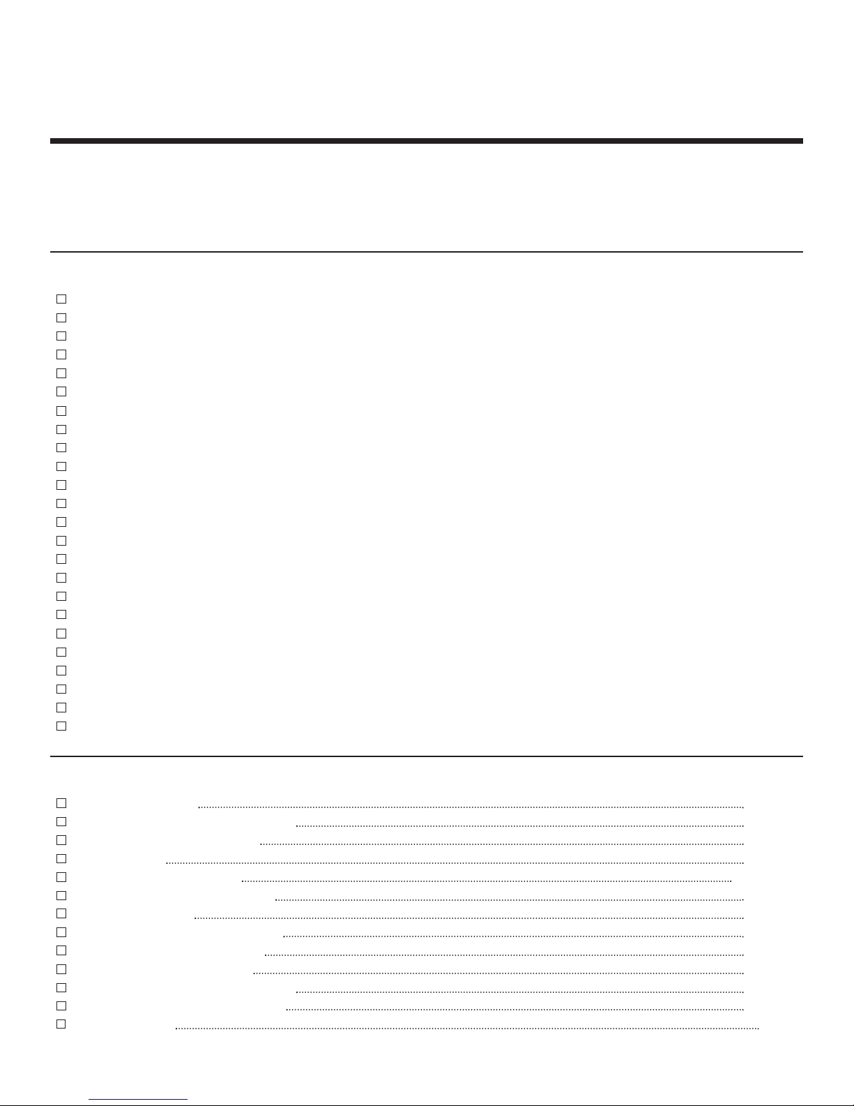
PARTS IDENTIFICATION
Switch PC Mount
witch 12 Position
S
9mm Nut
PC Board
Resistor
Washer
Alligator Clip
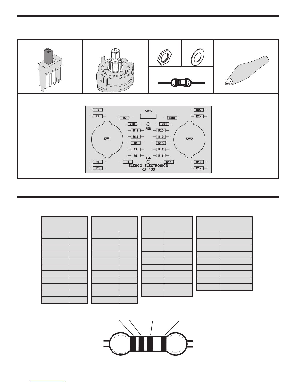
IDENTIFYING RESISTOR VALUES
Use the follo
wing inf
Color Digit
Blac
Brown 1
Red 2
Orange 3
Yellow 4
Green 5
Blue 6
Violet 7
ay
Gr
White 9
ormation as a guide in proper
BAND 1
1st Digit
k
0
8
BAND 2
2nd Digit
Color Digit
k
Blac
Brown 1
Red 2
Orange 3
Yellow 4
Green 5
Blue 6
Violet 7
ay
Gr
White 9
1
ly identifying the v
Multiplier
Color Multiplier
0
8
Black 1
Brown 10
Red 100
ange
Or
Yellow 10,000
Green 100,000
Blue 1,000,000
Silver 0.01
Gold 0.1
BANDS
2 Multiplier T
alue of resistors.
Color Tolerance
Silver ±10%
Gold ±5%
Brown ±1%
1,000
oler
ance
Red ±2%
Orange ±3%
Green ±0.5%
Blue ±0.25%
Violet ±0.1%
Resistance
Tolerance
-2-
Page 4

CONSTRUCTION
Introduction
The most important factor in assembling your K-37 Resistance Substitution Box Kit is good soldering
techniques. Using the proper soldering iron is of prime importance. A small pencil type soldering iron of 25 40 watts is recommended. The tip of the iron must be kept clean at all times and well tinned.
Safety Procedures
• Wear eye protection when soldering.
Locate soldering iron in an area where you do not have to go around it or reach over it.
•
• Do not hold solder in your mouth. Solder contains lead and is a toxic substance. Wash your hands
thoroughly after handling solder.
• Be sure that there is adequate ventilation present.
Assemble Components
In all of the following assembly steps, the components must be installed on the top side of the PC board unless
otherwise indicated. The top legend shows where each component goes. The leads pass through the
corresponding holes in the board and are soldered on the foil side.
Use only rosin core solder of 63/37 alloy.
DO NOT USE ACID CORE SOLDER!
What Good Soldering Looks Like
A good solder connection should be bright, shiny,
smooth, and uniformly flowed over all surfaces.
1. Solder all components from
the copper foil side only.
Push the soldering iron tip
against both the lead and
the circuit board foil.
2. Apply a small amount of
solder to the iron tip. This
allows the heat to leave the
iron and onto the f
Immediately apply solder to
the opposite side of the
connection, away from the
iron. Allow the heated
component and the circuit
oil to melt the solder.
f
Allow the solder to flo
3.
around the connection.
Then, remove the solder
and the iron and let the
connection cool.
solder should have flowed
smoothly and not lump
around the wire lead.
4.
Here is what a good solder
connection looks like.
oil.
The
Component Lead
Foil
Solder
Foil
w
Solder
F
oil
Soldering Iron
Circuit Board
Soldering Iron
Soldering Iron
Types of Poor Soldering Connections
1. Insufficient heat - the
solder will not flow onto the
lead as shown.
2. Insufficient solder - let the
solder flow over the
connection until it is
vered. Use just enough
co
solder to co
connection.
3. Excessive solder - could
make connections that you
did not intend to between
adjacent foil areas or
minals.
ter
4. Solder bridges - occur
when solder runs between
circuit paths and creates a
short circuit. This is usually
caused by using too much
solder. To correct this,
simply dr
iron across the solder
bridge as shown.
ag y
ver the
our solder
ing
Rosin
Soldering iron positioned
incorrectly.
Solder
Component Lead
Solder
Solder
Foil
ing Iron
Dr
Gap
ag
-3-
Page 5

ASSEMBLY INSTRUCTIONS
B
egin the PC board assembly with resistor R12. Be sure to identify the correct value by reading the color code.
P
lace the resistor into the PC board with the leads coming out on the copper foil side. Solder in place and clip
off the excess leads, close to the connection.
R12 - 4.7kW 5% 1/2W Resistor
(yellow-violet-red-gold)
R11 - 3.3kW 5% 1/2W Resistor
(orange-orange-red-gold)
R10 - 2.2kW 5% 1/2W Resistor
(red-red-red-gold)
R8 - 680W 5% 1/2W Resistor
(blue-gray-brown-gold)
R7 - 470W 5% 1/2W Resistor
(yellow-violet-brown-gold)
R9 - 1kW 5% 1/2W Resistor
(brown-black-red-gold)
R1 - 10W 5% 1/2W Resistor
(brown-black-black-gold)
R2 - 22W 5% 1/2W Resistor
(red-red-black-gold)
R3 - 47W 5% 1/2W Resistor
(yellow-violet-black-gold)
R5 - 220W 5% 1/2W Resistor
(red-red-brown-gold)
R19 - 100kW 5% 1/2W Resistor
(brown-black-yellow-gold)
R20 - 220kW 5% 1/2W Resistor
(red-red-yellow-gold)
R21 - 330kW 5% 1/2W Resistor
(orange-orange-yellow-gold)
R23 - 680kW 5% 1/2W Resistor
(blue-gray-yellow-gold)
R24 - 1MW 5% 1/2W Resistor
(brown-black-green-gold)
R22 - 470kW 5% 1/2W Resistor
(yellow-violet-yellow-gold)
R18 - 68kW 5% 1/2W Resistor
(blue-gray-orange-gold)
R17 - 47kW 5% 1/2W Resistor
(yellow-violet-orange-gold)
R16 - 33kW 5% 1/2W Resistor
(orange-orange-orange-gold)
R14 - 10kW 5% 1/2W Resistor
(brown-black-orange-gold)
R6 - 330W 5% 1/2W Resistor
(orange-orange-brown-gold)
R4 - 100W 5% 1/2W Resistor
(brown-black-brown-gold)
R13 - 6.8kW 5% 1/2W Resistor
(blue-gray-red-gold)
R15 - 22kW 5% 1/2W Resistor
(red-red-orange-gold)
-4-
Page 6

SW3 - PC Mount Switch
SW1
Mount SW3 in the place shown on the PC board.
Solder into place.
Red Test Lead
Black Test Lead
Cut off 1 1/2” of wire off of both the red and black
wires (SAVE them for later use). Strip 1/4” of
insulation off both ends of the 10 1/2” red and black
wires and insert them into the holes as marked on
the PC board. Solder into place. Tie a knot with
both wires 1 1/2” from the surface of the PC board
as shown in Figure 1. Pull the wires through the
hole in the cover. Slide the alligator boots onto the
wires. Solder the wires to the alligator clips. Then,
slide the boots onto the clips.
SW2
Bend the tab on the switches
down (see Figure 2). Attach the
two switches loosely to the front
panel with the 9mm nuts and
washers. Line up the holes of
the PC board with the switch
lugs, as shown in Figure 3. Be
sure that the board lays flat,
then solder the lugs into place.
Tighten down the 9mm nuts.
Washer
9mm Nut
Figure 3
Bend Tab Over
Figure 2
PC Board
Cover
Bend T
Figure 1
Wiper Pin
abs
Over Wire
Strip 1/4”
red and black wires. Solder one end of the wire to the
wiper pin on the 12 position switches and the other to
the pad without a hole
Place the knobs loosely on the switch posts. Push
the slide switch to the “W” position. Connect an ohm
meter to the output.
with the v
knob onto the shaft. Push the slide switch to the
“KW” position and repeat the same procedure.
Jumper Wires
Jumper wire from SW1
Jumper wire from SW2
of insulation off of both ends of the 1 1/2”
, as sho
wn in Figure 4.
Installation of Knobs if an Ohm Meter is A
Line up the pointer of the knob
alue shown on your meter, then push the
Wiper Pin
vailab
le
SW2
SW1
Figure 4
-5-
Page 7

Installation of Knobs without an Ohm Meter
C Board
P
ug
L
If an ohm meter is not available, turn both switches
so that the wiper contact is in the position shown in
Figure 5. Start with switch SW1, follow the copper
run on the PC board from the lug in contact with the
wiper to the 470W (R7) resistor, to be sure that the
switch is set in the proper position. Align the knob
iper Contact
on the SW1 (W) switch to the 470 position, push the
W
knob onto the shaft. Follow the same procedure for
switch SW2 (KW), except follow the copper run to
the 6.8KW (R13) resistor. Align the knob on the
SW2 (KW) switch to the 6.8 position.
Figure 5
TESTING THE CIRCUIT
The following test is to be made with your meter to determine that the resistors are in their correct circuit
positions. The resistors used in your circuit are gold banded with a tolerance of +5%. That means that a 10kW
resistor could measure between 9,500W and 10,500W and be correct. Each of the 24 resistance value positions
will be tested and recorded in the chart below.
SW1 WWPOSITION
Value Position Meter Reading
10W
22W
47W
100W
220W
330W
470W
680W
1000W
2200W
3300W
4700W
SCHEMATIC DIAGRAM
SW2 KWWPOSITION
Value Position Meter Reading
6.8KW
10KW
22KW
33KW
47KW
68KW
100KW
220KW
330KW
470KW
680KW
1MW
-6-
Page 8

Elenco®Electronics, Inc.
150 Carpenter Avenue
Wheeling, IL 60090
(847) 541-3800
Web site: www.elenco.com
e-mail: elenco@elenco.com
 Loading...