

Page 1
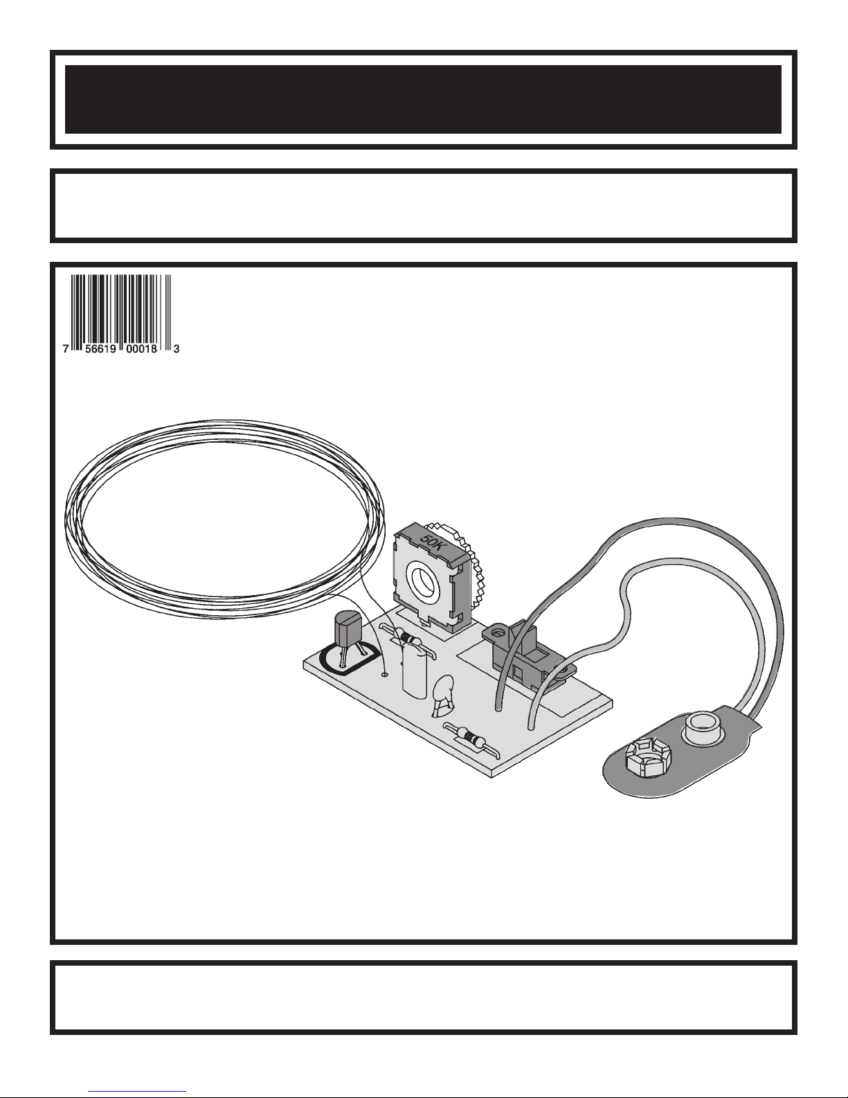
METAL DETECTOR KIT
MODEL K-26
Assembly and Instruction Manual
Elenco
Copyright © 2003, 1989 by ElencoTMElectronics, Inc. All rights reserved. Revised 2003 REV-D 753226
No part of this book shall be reproduced by any means; electronic, photocopying, or otherwise without written permission from the publisher.
TM
Electronics, Inc.
Page 2
PARTS LIST
If you are a student, and any parts are missing or damaged, please see instructor or bookstore.
If you purchased this metal detector kit from a distributor, catalog, etc., please contact Elenco
(address/phone/e-mail is at the back of this manual) for additional assistance, if needed.
RESISTORS
Qty. Symbol Description Color Code Part #
1 R2 4.7kW 1/4W 5% yellow-violet-red-gold 144700
1 R1 15kW 1/4W 5% brown-blue-orange-gold 151500
1 P1 Trim Pot 50kW 191552
CAPACITORS
Qty. Symbol Description Part #
1 C1 680pF Discap (681) 226880
1 C2 .0015mF Discap (152) 231517
SEMICONDUCTORS
Qty. Symbol Description Part #
1 Q1 Transistor MPS5172 325172
MISCELLANEOUS
Qty. Symbol Description Part #
1 PC Board 518026
1 S1 Switch 541102
1 Solder Roll 24” 551124
1 B1 Battery Snap 9V 590098
1 Wire #26 Enamel 45’ 846000
TM
Electronics
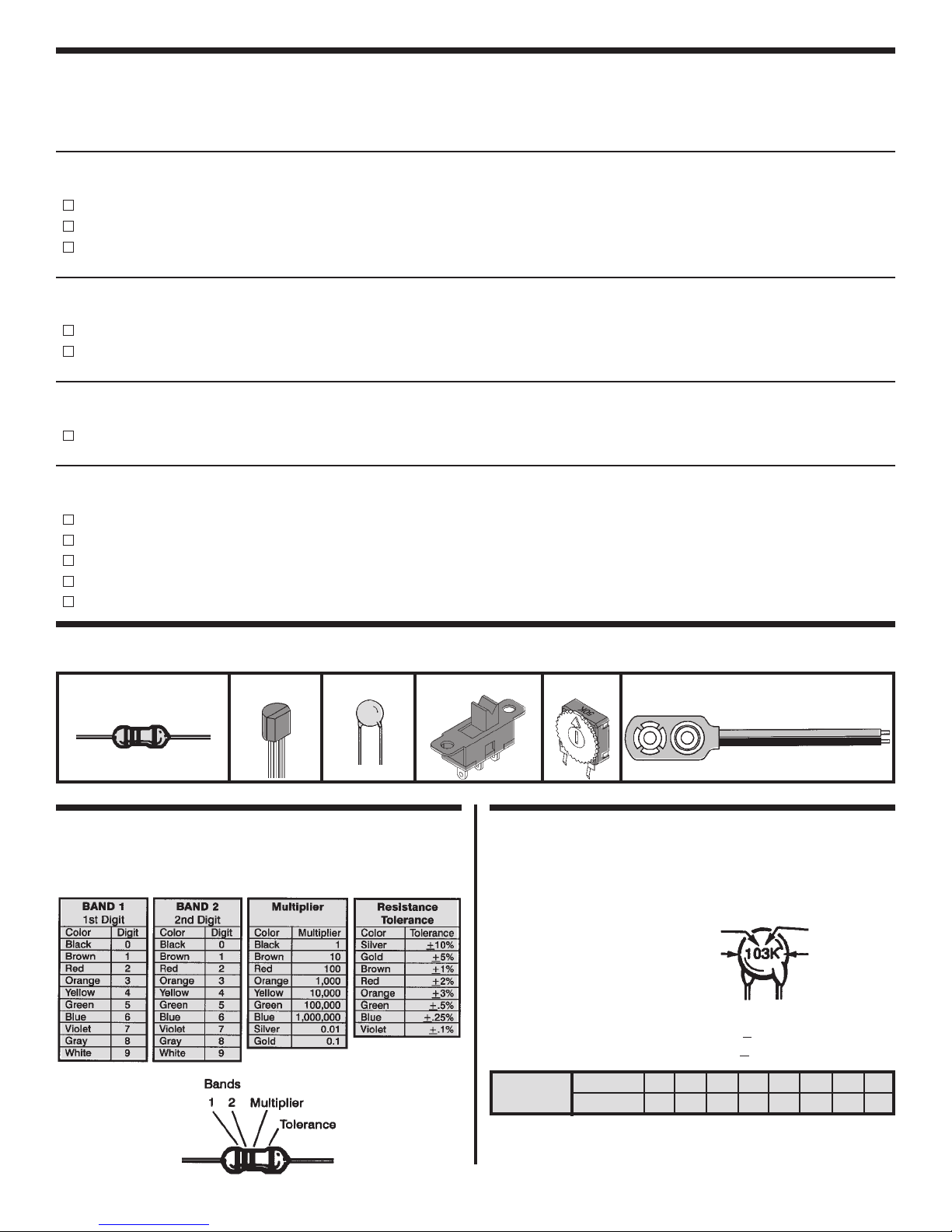
PARTS IDENTIFICATION
Resistor Transistor
Capacitor
Discap
IDENTIFYING RESISTOR VALUES
Use the following information as a guide in properly
identifying the value of resistors.
Switch
Battery SnapTrim Pot
IDENTIFYING CAPACITOR VALUES
Capacitors will be identified by their capacitance value in
pF (picofarads), nF (nanofarads), or mF (microfarads).
Most capacitors will have their actual value printed on
them. Some capacitors may have their value printed in the
following manner.
The above value is 10 x 1,000 = 10,000pF or .01mF
The letter K indicates a tolerance of +
The letter J indicates a tolerance of +
Multiplier
For the No. 0 1 2 3 4 5 8 9
Multiply By 1 10 100 1k 10k 100k .01 0.1
Second Digit
First Digit
10%
5%
Multiplier
Tolerance
Note: The letter “R” may be used at times to
signify a decimal point; as in 3R3 = 3.3
-1-
Page 3
INTRODUCTION
There are many buried treasures waiting to be
found. While everyone dreams of finding a fortune
in gold coins, few do anything to look for them. Now
with the K-26 Metal Detector, you have a chance.
Although you may not find a fortune in gold, you
should find a few silver coins if you work the
beaches or parks. If nothing else, you’re sure to
have fun with this metal detector.
The Metal Detector basically is an oscillator that
transmits in the AM radio band. When a radio is
placed near the oscillator, it will emit an audible
tone. The frequency transmitted by the oscillator will
vary when brought close to a metal object. Thus,
the tone produced by the radio will vary in pitch,
indicating that a metal is present. We shall study the
theory of how the oscillator works and why its
frequency changes when brought near a metal
object.
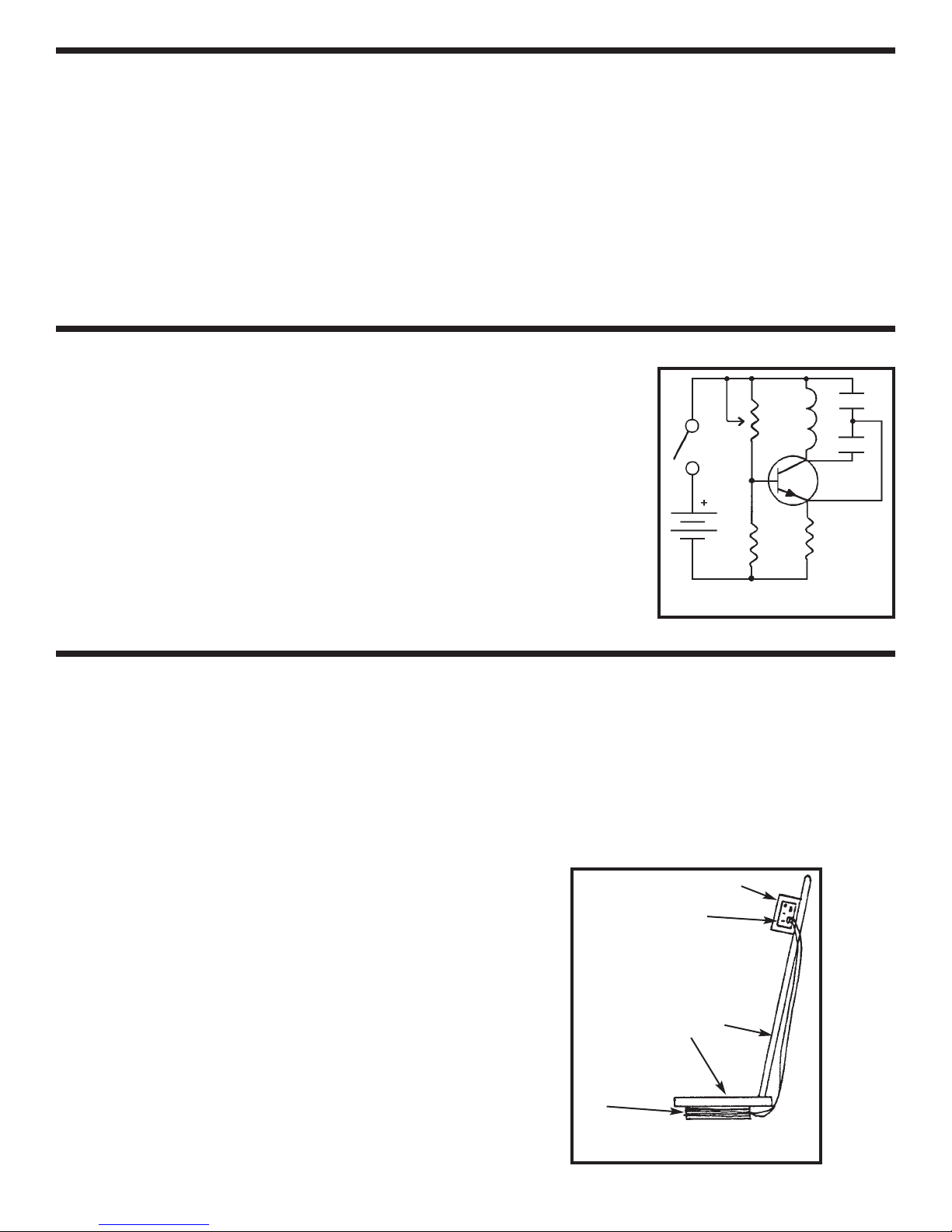
THE BASIC OSCILLATOR
Figure 1 shows the basic circuit of the oscillator. When the switch SW1 is
closed, a current will flow in the P1-R1 ciricuit. This will turn on transistor Q1
and send a current into the inductor-capacitor circuit (LC circuit). The inductor
is made by winding a 5” diameter coil with 30 turns of copper wire. The LC
circuit is the heart of the oscillator. Every LC circuit has its own resonance
frequency. The resonance frequency of this circuit is in the AM radio band.
If we take part of the energy in the LC circuit and feed it to the emitter of Q1,
the transistor will amplify this signal and cause the circuit to oscillate at the LC
resonance frequency. By varying P1, the current through transistor Q1 will
change, thus forcing the frequency of the oscillator to change slightly.
S1
B1
P1
R1
C1
L1
Q1
C2
R2
THE METAL DETECTOR OPERATION
Obtain a small portable AM radio and place it near
the Metal Detector. Tune the radio around the
midband and away from radio stations, you should
hear only static. If there are AM stations nearby you
will get whistling. This is because the metal detector
oscillator is mixing with the frequency of the AM
station. Now turn control P1 until the static gets
quiet. The metal detector is now tuned to the AM
radio frequency. Now take a piece of iron metal and
bring it close to the detector. Note the change in the
static in the radio or a change in the pitch of the
whistle. This is because you have increased the
inductance of the coil and thus changed the
resonance frequency of the circuit. The radio is now
tuned to the new oscillator frequency.
Magnetic fields move easier in the presence of iron,
nickel and other materials. Thus the inductance of
the coil will increase when these metals are present.
This increase in inductance will cause the LC circuit
to oscillate at a lower frequency. These magnetic
fields are disturbed when in the presence of silver,
aluminum, copper and other highly conductive
Figure 1
metals. Thus, when these metals are brought near
the coil, the frequency transmitted by the oscillator
increases. The radio responds to the oscillator
changes.
Now you have some understanding of how the
Metal Detector works. Go out and look for your
fortune. Wish you lots of luck.
AM Radio
Attach the circuit
board to the radio
Non-metal Support
L1
Figure 2
-2-
Page 4

CONSTRUCTION
Introduction
The most important factor in assembling your K-26 Metal Detector Kit is good soldering techniques. Using the
proper soldering iron is of prime importance. A small pencil type soldering iron of 25 - 40 watts is
recommended. The tip of the iron must be kept clean at all times and well tinned.
Safety Procedures
• Wear eye protection when soldering.
Locate soldering iron in an area where you do not have to go around it or reach over it.
•
• Do not hold solder in your mouth. Solder contains lead and is a toxic substance. Wash your hands
thoroughly after handling solder.
• Be sure that there is adequate ventilation present.
Assemble Components
In all of the following assembly steps, the components must be installed on the top side of the PC board unless
otherwise indicated. The top legend shows where each component goes. The leads pass through the
corresponding holes in the board and are soldered on the foil side.
Use only rosin core solder of 63/37 alloy.
DO NOT USE ACID CORE SOLDER!
What Good Soldering Looks Like
A good solder connection should be bright, shiny,
smooth, and uniformly flowed over all surfaces.
1. Solder all components from
the copper foil side only.
Push the soldering iron tip
against both the lead and
the circuit board foil.
2. Apply a small amount of
solder to the iron tip. This
allows the heat to leave the
iron and onto the foil.
Immediately apply solder to
the opposite side of the
connection, away from the
iron. Allow the heated
component and the circuit
foil to melt the solder.
3. Allow the solder to flow
around the connection.
Then, remove the solder
and the iron and let the
connection cool. The
solder should have flowed
smoothly and not lump
around the wire lead.
4.
Here is what a good solder
connection looks like.
Component Lead
Foil
Solder
Foil
Solder
Foil
Soldering Iron
Circuit Board
Soldering Iron
Soldering Iron
Types of Poor Soldering Connections
1. Insufficient heat - the
solder will not flow onto the
lead as shown.
2. Insufficient solder - let the
solder flow over the
connection until it is
covered. Use just enough
solder to cover the
connection.
3. Excessive solder - could
make connections that you
did not intend to between
adjacent foil areas or
terminals.
4. Solder bridges - occur
when solder runs between
circuit paths and creates a
short circuit. This is usually
caused by using too much
solder. To correct this,
simply drag your soldering
iron across the solder
bridge as shown.
Rosin
Soldering iron positioned
incorrectly.
Solder
Component Lead
Solder
Soldering Iron
Foil
Gap
Drag
-3-
Page 5

ASSEMBLE COMPONENTS TO THE PC BOARD
P1 - 50kW Potentiometer
R1 - 15kW 5% 1/4W Resistor
(brown-green-orange-gold)
Q1 - MPS5172 Transistor
(see Figure A)
L1 - Coil (see Figure B)
C2 - .0015mF Capacitor (152)
Figure A
Mount the transistor to the PC
board at the location shown.
Note the flat side of the transistor
and the marking on the PC
board. Solder and cut off the
excess leads.
S1 - Switch
B1 - Battery Snap -
wire into the positive (+) hole and the
black wire into the negative (--) hole.
Solder and cut off the excess leads.
R2 - 4.7kW 5% 1/4W Resistor
(yellow-violet-red-gold)
C1 - 680pF Discap (681)
Install the red
Figure B
Find the two ends of the coil. Using a file or a razor blade, strip the enamel
insulation from the wire 1/4” so the solder will make good contact with the wire.
Insert the ends of the coil into the PC board. Solder and cut off the excess
leads.
Flat
1/4”
1/4”
-4-
Page 6

TROUBLESHOOTING
Contact ElencoTMElectronics if you have any problems. DO NOT contact your place of purchase as they will
not be able to help you.
1. One of the most frequently occurring problems is
poor solder connections.
a) Tug slightly on all parts to make sure that
they are indeed soldered.
b) All solder connections should be shiny.
Resolder any that are not.
c) Solder should flow into a smooth puddle
rather than a round ball. Resolder any
connection that has formed into a ball.
d) Have any solder bridges formed? A solder
bridge may occur if you accidentally touch
an adjacent foil by using too much solder or
by dragging the soldering iron across
adjacent foils. Break the bridge with your
soldering iron.
2. Be sure that all components have been mounted
in their correct places.
a) Use a fresh 9V battery.
b) Be sure that the coil is soldered properly.
The two ends of the wire should be clear of
insulation, so that the solder can make good
contact with the wire.
c) Your most likely problem will be tuning the
metal detector oscillator to the radio. Start
at around the 1,000kHz spot on the radio.
Pick a spot that is clear of radio stations. You
should hear only static. Rotate the
potentiometer P1 very slowly until the static
gets quiet. If you cannot quiet the radio,
tune the radio to a higher frequency, around
1,300kHz and try adjusting the
potentiometer again. If still no luck, try a
lower frequency, around 700kHz. You
should be able to find a spot when the metal
detector oscillator has an effect. Moving a
piece of metal around the coil should
produce changes in the sound from the
radio.
SCHEMATIC DIAGRAM
PC BOARD FOIL SIDE
-5-
Page 7

QUIZ
1. The Metal Detector basic circuit is an ___________.
2. The Metal Detector transmits in the ___________ radio band.
3. The frequency of the oscillator changes when brought near ___________.
4. The LC circuit is the ___________ of the oscillator.
5. All LC circuits have a ___________ frequency.
6. An LC circuit has a coil and a ___________.
7. An inductor can be made by winding some wire into a ____________.
8. If part of the energy in the LC circuit in Figure 1 is fed to the emitter of Q1, the circuit will ___________.
9. When the radio and Metal Detector oscillators are at the ____________ frequency, the radio will be quiet.
10. Iron causes the LC circuit to oscillate at a _____________ frequency.
Answers: 1. oscillator; 2. AM; 3. metal; 4. heart; 5. resonance; 6. capacitor; 7. coil; 8. oscillate; 9. same; 10. lower
-6-
Page 8

ElencoTMElectronics, Inc.
150 W. Carpenter Avenue
Wheeling, IL 60090
(847) 541-3800
http://www.elenco.com
e-mail: elenco@elenco.com
 Loading...