

Page 1
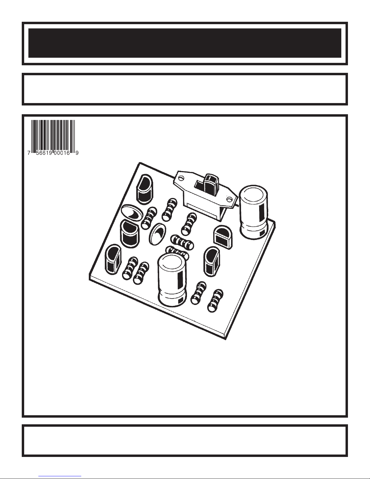
WHOOPER ALARM KIT
MODEL K-24
Assembly and Instruction Manual
Elenco Electronics, Inc.
Copyright © 1989 Elenco Electronics, Inc. Revised 2002 REV-D 753224
Page 2
PARTS LIST
If you are a student, and any parts are missing or damaged, please see instructor or bookstore.
If you purchased this whooper alarm kit from a distributor, catalog, etc., please contact Elenco Electronics
(address/phone/e-mail is at the back of this manual) for additional assistance, if needed.
RESISTORS
Qty. Symbol Description Color Code Part #
1 R8 100W 5% 1/4W brown-black-brown-gold 131000
2 R3, R6 1kW 5% 1/4W brown-black-red-gold 141000
1 R2 2.2kW 5% 1/4W red-red-red-gold 142200
1 R5 6.8kW 5% 1/4W blue-gray-red-gold 146800
2 R1, R9 15kW 5% 1/4W brown-green-orange-gold 151500
1 R4 22kW 5% 1/4W red-red-orange-gold 152200
1 R7 27kW 5% 1/4W red-violet-orange-gold 152700
CAPACITORS
Qty. Symbol Value Description Part #
2 C2, C3 .047mF (473) Discap 244780
2 C1, C4 100mF Electrolytic 281044
SEMICONDUCTORS
Qty. Symbol Value Description Part #
3 Q1, Q3, Q4 2N3904 Transistor 323904
1 Q2 2N3906 Transistor 323906
1 Q5 MPS6531 Transistor 326531
MISCELLANEOUS
Qty. Symbol Description Part #
1 PC Board 518024
1 S1 Switch Slide SPDT 541102
1 Solder Roll 24” 551124
1 B1 Battery Snap 9V 590098
1 SPK1 Speaker 8W 590102
2 Wire 4” Blue 814620
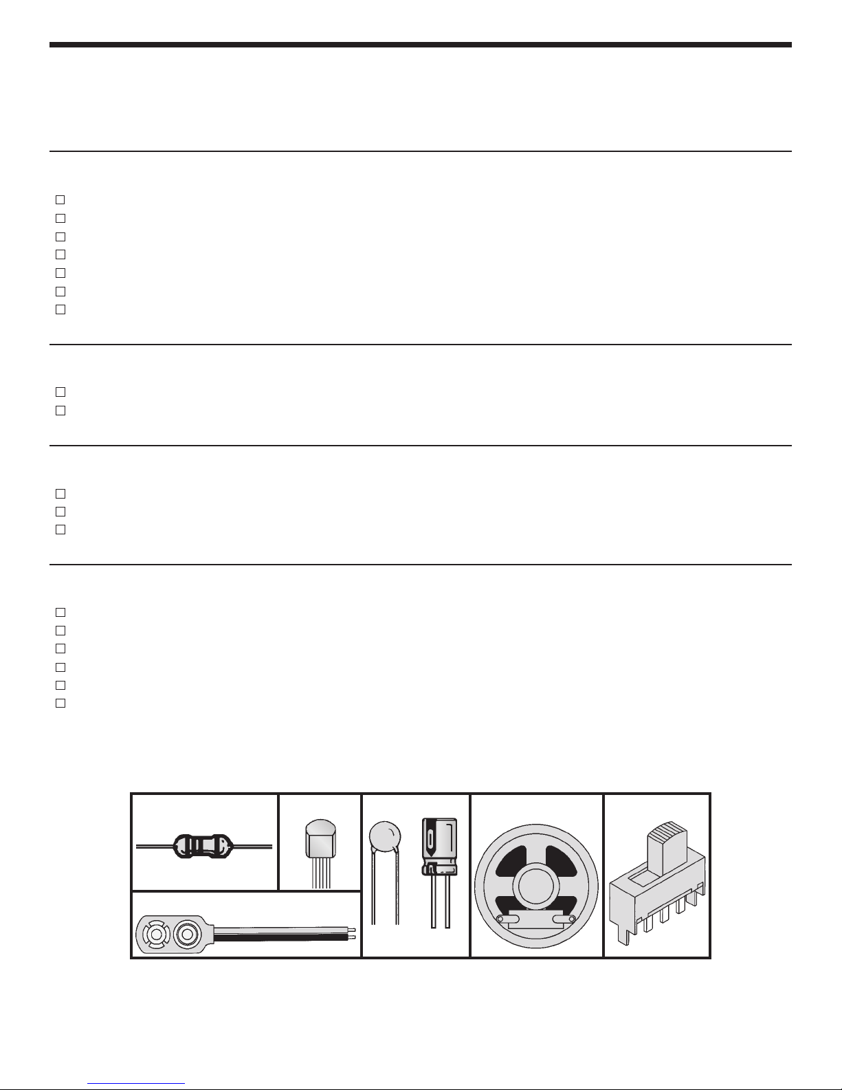
PARTS IDENTIFICATION
Resistor Transistor
Battery Snap
Capacitors
Discap
Electrolytic
Speaker
Switch
-1-
Page 3
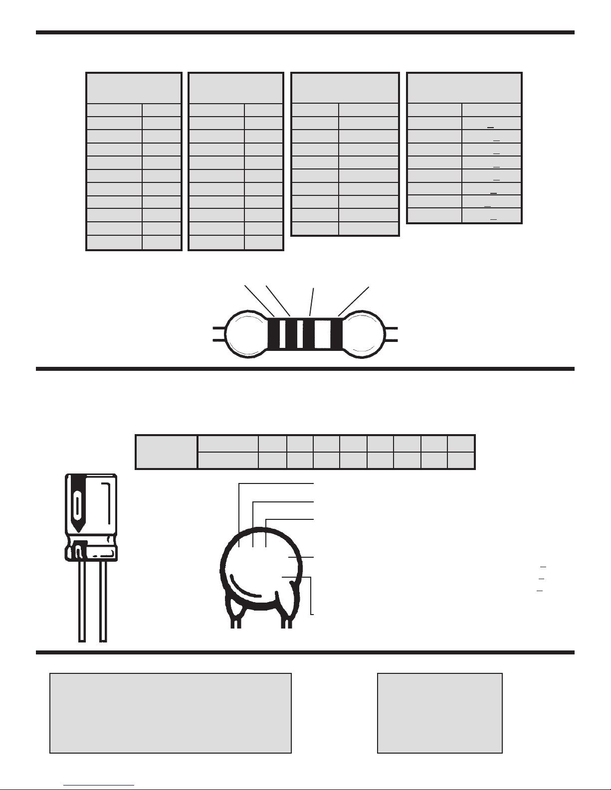
IDENTIFYING RESISTOR VALUES
Use the following information as a guide in properly identifying the value of resistors.
BAND 1
1st Digit
Color Digit
Black 0
Brown 1
Red 2
Orange 3
Yellow 4
Green 5
Blue 6
Violet 7
Gray 8
White 9
BAND 2
2nd Digit
Color Digit
Black 0
Brown 1
Red 2
Orange 3
Yellow 4
Green 5
Blue 6
Violet 7
Gray 8
White 9
2 Multiplier Tolerance
1
Multiplier
Color Multiplier
Black 1
Brown 10
Red 100
Orange 1,000
Yellow 10,000
Green 100,000
Blue 1,000,000
Silver 0.01
Gold 0.1
BANDS
Resistance
Tolerance
Color Tolerance
Silver +10%
Gold +
Brown +1%
Red +2%
Orange +
Green +.5%
Blue +.25%
Violet +
5%
3%
.1%
IDENTIFYING CAPACITOR VALUES
Capacitors will be identified by their capacitance value in pF (picofarads), nF (nanofarads), or mF (microfarads). Most
capacitors will have their actual value printed on them. Some capacitors may have their value printed in the following
manner. The maximum operating voltage may also be printed on the capacitor.
Multiplier
10mF 16V
For the No.01234589
Multiply By 1 10 100 1k 10k 100k .01 0.1
Note: The letter “R” may be used at times
to signify a decimal point; as in 3R3 = 3.3
The letter M indicates a tolerance of +
The letter K indicates a tolerance of +10%
The letter J indicates a tolerance of +5%
103K
100V
First Digit
Second Digit
Multiplier
Tolerance
Maximum Working Voltage
20%
The value is 10 x 1,000 = 10,000pF or .01mF 100V
METRIC UNITS AND CONVERSIONS
Abbreviation Means Multiply Unit By Or
p Pico .000000000001 10
n nano .000000001 10
m micro .000001 10
m milli .001 10
– unit 1 10
k kilo 1,000 10
M mega 1,000,000 10
-12
-9
-6
-3
0
3
6
-2-
1. 1,000 pico units = 1 nano unit
2. 1,000 nano units = 1 micro unit
3. 1,000 micro units= 1 milli unit
4. 1,000 milli units = 1 unit
5. 1,000 units = 1 kilo unit
6. 1,000 kilo units= 1 mega unit
Page 4

MINIATURE RADIO TRANSMITTER
The Whooper Alarm puts out a wavering sound that is sure to startle an
intruder. It can be used independently or as an accessory to the Burglar
Alarm Kit K-23.
The Whooper Alarm circuit consists of two oscillators, a low frequency
oscillator which drives a higher frequency unit at a predetermined rate.
The high frequency oscillator drives an output transistor which powers the
speaker.
CIRCUIT OPERATION
Figure 1 shows the circuits of the low frequency oscillator. When the
power is first applied to this circuit, transistors Q1 and Q2 will not conduct.
This is because the base of transistor Q2 is about 5.4V while the emitter
is at zero volts.
A current is flowing in resistor R2 charging capacitor C1. When the voltage
across C1 reaches 6V, transistor Q2 starts sending a current in the
collector of Q1. The current in the collector of Q1 is mulitplied by the gain
of transistor Q1 and this rapidly turns on transistor Q2. Capacitor C1
quickly discharges through resistor R8 as shown in Figure 2. Note that C1
charges through a 2200W resistor R2, but discharges through a 100W
resistor R8. Thus, the charge to discharge ratio is 22:1. When C1 is
discharged, Q1 and Q2 turn off and the whole cycle repeats itself.
Figure 1
HIGH FREQUENCY OSCILLATOR
The circuit of the high frequency oscillator is shown in Figure 3.
Transistors Q3 and Q4 are wired as amplifier stages. The bias for these
amplifiers are controlled by the sawtooth of Figure 2. These amplifiers
normally would amplify the low frequency pulses, except for the addition of
capacitor C3. This capacitor takes the output of Q4 and feeds it in phase
to the input of Q3. This causes the circuit to oscillate. The frequency of
oscillation is controlled by the RC time constants of C3 and R6. The
frequency of oscillation is about 1,000 cycles per second. This frequency
is modulated with the low frequency oscillations to produce the Whooper
Alarm sounds. Transistor Q5 further amplifies the signals and drives the
speaker.
Figure 3
Volts
Time
Figure 2
-3-
Page 5

CONSTRUCTION
Introduction
The most important factor in assembling your K-24 Whooper Alarm Kit is good soldering techniques. Using the
proper soldering iron is of prime importance. A small pencil type soldering iron of 25 - 40 watts is
recommended. The tip of the iron must be kept clean at all times and well tinned.
Safety Procedures
• Wear eye protection when soldering.
Locate soldering iron in an area where you do not have to go around it or reach over it.
•
• Do not hold solder in your mouth. Solder contains lead and is a toxic substance. Wash your hands
thoroughly after handling solder.
• Be sure that there is adequate ventilation present.
Assemble Components
In all of the following assembly steps, the components must be installed on the top side of the PC board unless
otherwise indicated. The top legend shows where each component goes. The leads pass through the
corresponding holes in the board and are soldered on the foil side.
Use only rosin core solder of 63/37 alloy.
DO NOT USE ACID CORE SOLDER!
What Good Soldering Looks Like
A good solder connection should be bright, shiny,
smooth, and uniformly flowed over all surfaces.
1. Solder all components from
the copper foil side only.
Push the soldering iron tip
against both the lead and
the circuit board foil.
2. Apply a small amount of
solder to the iron tip. This
allows the heat to leave the
iron and onto the foil.
Immediately apply solder to
the opposite side of the
connection, away from the
iron. Allow the heated
component and the circuit
foil to melt the solder.
3. Allow the solder to flow
around the connection.
Then, remove the solder
and the iron and let the
connection cool. The
solder should have flowed
smoothly and not lump
around the wire lead.
4.
Here is what a good solder
connection looks like.
Component Lead
Foil
Solder
Foil
Solder
Foil
Soldering Iron
Circuit Board
Soldering Iron
Soldering Iron
Types of Poor Soldering Connections
1. Insufficient heat - the
solder will not flow onto the
lead as shown.
2. Insufficient solder - let the
solder flow over the
connection until it is
covered. Use just enough
solder to cover the
connection.
3. Excessive solder - could
make connections that you
did not intend to between
adjacent foil areas or
terminals.
4. Solder bridges - occur
when solder runs between
circuit paths and creates a
short circuit. This is usually
caused by using too much
solder. To correct this,
simply drag your soldering
iron across the solder
bridge as shown.
Rosin
Soldering iron positioned
incorrectly.
Solder
Component Lead
Solder
Soldering Iron
Foil
Gap
Drag
-4-
Page 6

ASSEMBLE COMPONENTS TO THE PC BOARD
SPK - Speaker: Cut two 4”
wires and strip 1/8” of insulation
off of both wires. Solder a wire to
each lug of the speaker and then
insert the other end of the wires to
the PC board in the place shown
on the top legend.
Jumper Wire (see Figure C)
Red
Q3 - 2N3904 Transistor
(see Figure A)
Black
B1 - Battery Snap: Insert the
red wire into the positive (+) hole
and the black wire into the
negative hole. Solder and cut off
the excess leads.
R3 - 1kW 5% 1/4W Resistor
(brown-black-red-gold)
R6 - 1kW 5% 1/4W Resistor
(brown-black-red-gold)
C3 - .047mF (473) Discap
Q4 - 2N3904 Transistor
(see Figure A)
Q5 - MPS 6531 Transistor
(see Figure A)
R9 - 15kW 5% 1/4W Resistor
(brown-green-orange-gold)
R8 - 100W 5% 1/4W Resistor
(brown-black-brown-gold)
C2 - .047mF (473) Discap
C1 - 100mF Electrolytic Cap.
(see Figure B)
Figure A
Mount the transistor with the
flat side in the same direction
as shown on the PC board.
Solder and cut off the excess
leads.
Figure B
Electrolytic capacitors have
polarity. Be sure to mount
them with the negative (–)
lead (marked on side) in the
correct hole.
C4 - 100mF Electrolytic Cap.
S1 - Slide Switch
Q1 - 2N3904 Transistor
(see Figure A)
R1 - 15kW 5% 1/4W Resistor
(brown-green-orange-gold)
Q2 - 2N3906 Transistor
(see Figure A)
R5 - 6.8kW 5% 1/4W Resistor
(blue-gray-red-gold)
R4 - 22kW 5% 1/4W Resistor
(red-red-orange-gold)
R2 - 2.2kW 5% 1/4W Resistor
(red-red-red-gold)
R7 - 27kW 5% 1/4W Resistor
(red-violet-orange-gold)
Figure C
Use a discarded resistor lead
to form a jumper wire.
Flat
Polarity
Marking
Foil Side of PC Board
-5-
Page 7

TROUBLESHOOTING
Consult your instructor or contact Elenco Electronics if you have any problems. DO NOT contact your place of
purchase as they will not be able to help you.
1. One of the most frequently occurring problems is poor solder connections.
a) Tug slightly on all parts to make sure that they are indeed soldered.
b) All solder connections should be shiny. Resolder any that are not.
c) Solder should flow into a smooth puddle rather than a round ball. Resolder any connection that has
formed into a ball.
d) Have any solder bridges formed? A solder bridge may occur if you accidentally touch an adjacent foil
by using too much solder or by dragging the soldering iron across adjacent foils. Break the bridge with
your soldering iron.
COMPONENT CHECK
1. Be sure that all of the components have been mounted in their correct places.
2. Be sure that the electrolytic capacitors C1 and C4 have been installed correctly. These capacitors have
polarity, the negative and positive leads must be in the correct holes, as shown on the top legend of the PC
board.
3. Be sure that transistors Q1 - Q5 have been installed correctly. The flat side should be in the same direction
as shown on the top legend.
4. Use a fresh 9 volt battery.
5. Read the circuit operation lesson manual to familiarize yourself with the workings of the circuit.
SCHEMATIC DIAGRAM
-6-
Page 8

QUIZ
1. The Whooper Alarm has ___________ oscillators.
2. The low frequency oscillations are generated by transistors __________ and __________.
3. The high frequency oscillations are generated by transistors __________ and __________.
4. When the power is first turned on, the voltage at the base of Q2 is ___________.
5. When the power is first turned on, the voltage across C1 is ___________.
6. Capacitor C1 charges through resistor _______ and discharges through resistor __________.
7. The charge to discharged ratio on C1 is ___________.
8. Capacitor C3 causes transistor Q3 and Q4 to _____________.
9. The frequency of oscillation of Q3 and Q4 is about ____________ cycles per second.
10. The speaker is driven by transistors ________ and ________.
Elenco Electronics, Inc.
150 W. Carpenter Avenue
Wheeling, IL 60090
(847) 541-3800
http://www.elenco.com
e-mail: elenco@elenco.com
Answers: 1) two; 2) Q1, Q2; 3) Q3, Q4; 4) 5.4V; 5) zero; 6) R2, R8; 7) 22:1; 8) oscillate; 9) 1,000; 10) Q4, Q5
 Loading...