

Page 1
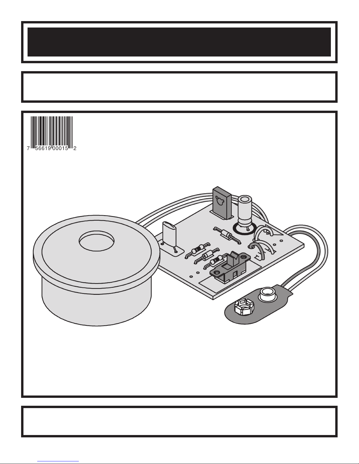
BURGLAR ALARM KIT
MODEL K-23
Assembly and Instruction Manual
Elenco®Electronics, Inc.
ight © 2004, 1989 Elenco
yr
Cop
t of this book shall be reproduced b
No par
®
Electronics
y means; electronic, photocopying, or otherwise without written permission from the publisher.
y an
, Inc.
vised 2004 REV
Re
-O 753223
Page 2
PARTS LIST
If you are a student, and any parts are missing or damaged, please see instructor or bookstore.
If you purchased this kit from a distributor, catalog, etc., please contact Elenco
mail is at the back of this manual) for additional assistance, if needed. DO NOT contact your place of purchase
as they will not be able to help you.
RESISTORS
Qty. Symbol Value Color Code Part #
2 R1, R2 39kΩ 5% 1/4W orange-white-orange-gold 153900
CAPACITORS
Qty. Symbol Value Description Part #
1 C2 .1µF (104) Mylar 251017
1 C1 47µF (103) Electrolytic 274744
SEMICONDUCTORS
Qty. Symbol Value Description Part #
2 D1, D2 1N4001 Diode 314001
1 SCR1 C106B1 or T106B1 SCR 319106
MISCELLANEOUS
Qty. Symbol Description Part #
1 PC Board 518023
1 S1 Switch 541102
24” Solder Roll 551124
1 B1 Battery Snap 590098
1 A1 Buzzer 595200
1 Screw #8 x 1/4” 641830
1 Solder Lug 661002
1 4” Black Wire 814120
5 4” Blue Wire 814620
®
Electronics (address/phone/e-
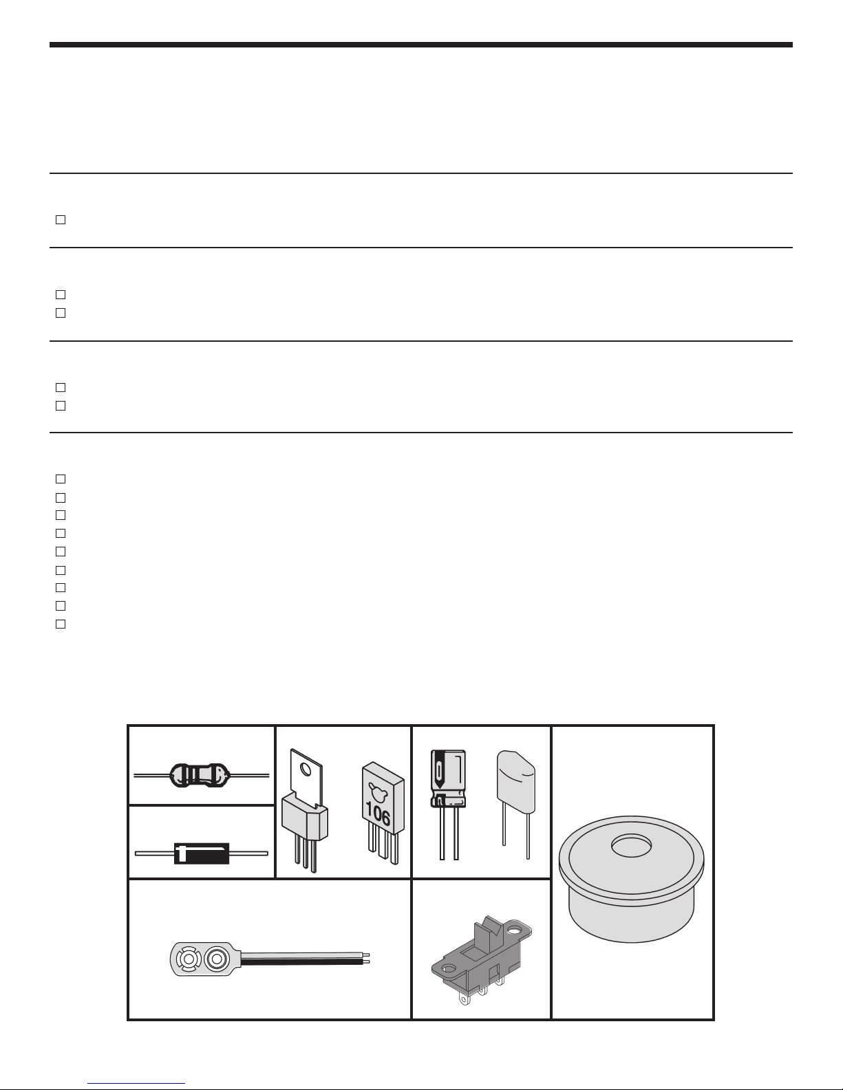
Resistor
Diode
Battery Snap
PARTS IDENTIFICATION
Electrolytic
-1-
Capacitor
Mylar
Switch
SCR
OR
Buzzer
Page 3

IDENTIFYING RESISTOR VALUES
Use the following information as a guide in properly identifying the value of resistors.
Bands
1 2
Multiplier
Tolerance
BAND 1
1st Digit
Color Digit
Black 0
Brown 1
Red 2
Orange 3
Yellow 4
Green 5
Blue 6
Violet 7
Gray 8
White 9
BAND 2
2nd Digit
Color Digit
Black 0
Brown 1
Red 2
Orange 3
Yellow 4
Green 5
Blue 6
Violet 7
Gray 8
White 9
Multiplier
Color Multiplier
Black 1
Brown 10
Red 100
Orange 1,000
Yellow 10,000
Green 100,000
Blue 1,000,000
Silver 0.01
Gold 0.1
Resistance
Tolerance
Color Tolerance
Silver +
Gold +
Brown +1%
Red +2%
Orange +3%
Green +.5%
Blue +.25%
Violet +.1%
10%
5%
IDENTIFYING CAPACITOR VALUES
Capacitors will be identified by their capacitance value in pF (picofarads), nF (nanofarads), or µF (microfarads).
Most capacitors will have their actual value printed on them. Some capacitors may have their value printed in
wing manner.
ollo
the f
Second Digit
First Digit
103K
100
Multiplier
Tolerance
Multiplier
For the No. 0 1 2 34589
Multiply By 1 10 100 1k 10k 100k .01 0.1
10µF 16V
Note: The letter “R” may be used at times to
signify a decimal point; as in 3R3 = 3.3
The above value is 10 x 1,000 = 10,000pF or .01µF
The letter K indicates a tolerance of +
The letter J indicates a tolerance of +
10%
5%
INTRODUCTION
The Elenco®Burglar Alarm is designed to set off an
m whenever the circuit is activated. There are
alar
o ways of activating the alarm; by opening a
tw
contact switch and/or by shorting a contact switch.
Once the alarm is ON, returning the switch back to
its original position will not turn off the alarm. A third
POWER SUPPLY
The Elenco®Burglar Alarm is designed to operate
from 9-15VDC. The electronic buzzer uses about
100 milliamps of current, so it is best to use an
alkaline battery to supply the necessary current.
The alkaline batter
uous use
contin
use the 12V car battery, as this will give almost
unlimited current. If an AC to DC power supply is
used, be sure that the supply can give 100mA at 915 volts.
y will last for about one hour of
When connected to an automobile
.
switch controls the turn-off of the alarm. There is no
limit to the n
placed to protect y
umber of the switches that can be
our property. You may use one for
each window and door in your house. There also is
a feature that allows use of the alarm to protect your
automobile and auto accessories.
The silicon controlled rectifier is the heart of the
Burglar Alarm. This device is an electronic switch
that allows current to flow only in one direction.
Figure 1 shows a
simple circuit of an
,
SCR.
When a
positive voltage is
applied to the
anode and a
negative voltage to
the cathode
current will flo
, no
.
w
Figure 1
-2-
Page 4

When we place a voltage to the gate, a current will
flow between the anode and cathode turning ON
the alarm buzzer. If we remove the voltage on the
gate, the current will continue to flow in the SCR.
ACTIVATING SWITCHES
There are two types of activating switches, the
normally open (N.O.) contacts and normally closed
(N.C.) contacts. Figure 2A shows the N.O. circuit.
Remember that the SCR needs gate voltage to fire.
When the N.O. switch is closed, the SCR will
conduct current and continue to do so even if the
N.O. switch is opened.
Figure 2B shows the circuit for a N.C. switch. Here,
while the switch is closed, no voltage will be seen at
the gate of the SCR. Once the switch is open, the
SCR will conduct and continue to do so until the
voltage is removed from the anode of the SCR. This
important turn on/no turn off feature prevents the
When we
uder from turning off the alar
intr
combine the N.O. and the N.C. circuits, a problem
occurs. The N.C. switch will short out the N.O. switch
voltage
two circuits. Figure 3 shows this circuit. The diode
D2 prevents the voltage from being shorted out
through the N.C
through the diode and into the gate of the SCR when
SW N.C. is open.
. To pre
vent this, we add a diode to isolate the
. switch.
Voltage from R1 will pass
m.
Thus, if a burglar opens the door, the alarm will go
off. Closing that door will not turn off the alarm, it
will continue to sound. The only way to turn it off is
to remove the power to the SCR.
Figure 2A Figure 2B
ELIMINATING FALSE ALARMS
When this alarm is used in an automobile, any
jarring of the contact switches may set off the alarm.
o prevent this, a capacitor (C2) is added to the
T
circuit. Figure 3 shows the location of C2. When the
N.C. or N.O. switch is first activated, the current
through R1 or R2 first goes to charge the capacitor.
After the capacitor is charged, then the v
oltage will
KEEPING THE ALARM ON
The alarm device used in this circuit is a buzzer.
This device operates by vibrating back and forth,
interrupting the current. Remember that the SCR
will tur
also loses its v
is added across the b
n off if the gate has no voltage and the anode
oltage to the anode
uzzer, as shown in Figure 4.
, a capacitor (C1)
EXTERNAL ALARM
The Burglar Alar
such as the rela
simply replace the b
the alarm is fired, the relay will close, setting off the
m can be used to control a relay,
o do so
our auto hor
y in y
uzzer with the relay. Whenever
n system.
T
Figure 3
build up enough to trigger the SCR. The time may
seem very fast, but in electronics, it is a long time
when y
(.000001 sec.). Thus, by adding capacitor C2, any
noise spike shorter than one millisecond will not fire
the alarm.
This capacitor will
keep the current
flowing in the SCR
whene
opens up
ou consider circuits react in microseconds
ver the buzzer
.
Figure 4
m. A diode (D1) is placed across the relay to
alar
oltage gener
,
e the e
v
remo
coil from damaging the SCR.
xcessiv
e v
ated by the relay
-3-
Page 5

CONSTRUCTION
Introduction
The most important factor in assembling your K-23 Burglar Alarm Kit is good soldering techniques. Using the
proper soldering iron is of prime importance. A small pencil type soldering iron of 25 - 40 watts is
recommended. The tip of the iron must be kept clean at all times and well tinned.
Safety Procedures
• Wear eye protection when soldering.
•
Locate soldering iron in an area where you do not have to go around it or reach over it.
• Do not hold solder in your mouth. Solder contains lead and is a toxic substance. Wash your hands
thoroughly after handling solder.
• Be sure that there is adequate ventilation present.
Assemble Components
In all of the following assembly steps, the components must be installed on the top side of the PC board unless
otherwise indicated. The top legend shows where each component goes. The leads pass through the
corresponding holes in the board and are soldered on the foil side.
Use only rosin core solder of 63/37 alloy.
DO NOT USE ACID CORE SOLDER!
What Good Soldering Looks Like
A good solder connection should be bright, shiny,
smooth, and uniformly flowed over all surfaces.
1. Solder all components from
the copper foil side only.
Push the soldering iron tip
against both the lead and
the circuit board foil.
2. Apply a small amount of
solder to the iron tip. This
allows the heat to leave the
iron and onto the foil.
Immediately apply solder to
the opposite side of the
connection, away from the
iron. Allow the heated
component and the circuit
foil to melt the solder.
3. Allow the solder to flow
around the connection.
Then, remove the solder
and the iron and let the
connection cool.
solder should have flowed
smoothly and not lump
around the wire lead.
4.
Here is what a good solder
connection looks like.
The
Component Lead
Foil
Solder
Foil
Solder
Foil
Soldering Iron
Circuit Board
Soldering Iron
Soldering Iron
Types of Poor Soldering Connections
1. Insufficient heat - the
solder will not flow onto the
lead as shown.
2. Insufficient solder - let the
solder flow over the
connection until it is
covered. Use just enough
solder to cover the
connection.
3. Excessive solder - could
make connections that you
did not intend to between
adjacent foil areas or
.
minals
ter
4. Solder bridges - occur
een
ing
ag y
uns betw
our solder
when solder r
circuit paths and creates a
short circuit. This is usually
caused by using too much
solder. To correct this,
simply dr
iron across the solder
bridge as shown.
Rosin
Soldering iron positioned
incorrectly.
Solder
Component Lead
Solder
Soldering Iron
Foil
Dr
Gap
ag
-4-
Page 6

ASSEMBLE COMPONENTS TO THE PC BOARD
Red
A1 - Buzzer (see Figure A)
Blue
C1 - 47µF Electrolytic Cap.
(see Figure B)
SCR1 - SCR (106B1)
D1 - 1N4001 Diode
(see Figure D)
R2 - 39kΩ 5% 1/4W Resistor
(orange-white-orange-gold)
C2 - .1µF (104) Mylar Cap.
D2 - 1N4001 Diode
(see Figure D)
Figure A
The buzzer in your kit may be one of any four types which require
different assembly procedures as follows:
1. (Buzzer with three lugs on back) - Solder a 4” blue wire and a 4” black wire to A1 on the PC
board. Solder the black wire to the (–) lug. Solder the blue wire to the (+) right lug (see
Figure A1).
2. (Buzz
3. (Buzzer with two wires - no bracket on back) - connect wires to the PC board with the black
4. (Buzzer with bracket on back) - remove the white wire with cutters. Solder a 4 inch wire to
5. (Buzzer with one wire) - a screw and lug are needed for the assembly as shown in the
Solder and cut off the excess leads.
er with one wire and lug on back) - solder a 4” blue wire to the lug. Insert the two wires
from the buzz
wire as shown in the diagram to the right.
one of the bracket lugs. Connect the 4 inch wire and the black wire as shown above.
diagram to the right.
er into the PC board, as shown on the top legend.
Black
Blue
B1 - Battery Snap -
and black wire through the hole in the PC
board as shown. Install the red wire into
the positive (+) hole and the black wire into
the negative (–) hole. Solder and cut off
the excess leads.
Insert the red
S1 - Slide Switch
R1 - 39kΩ 5% 1/4W Resistor
(orange-white-orange-gold)
Install the wire for the alarm
switches S2 and S3 in the places
shown on the top legend. Solder
them to the circuit board and cut
off the excess leads. S2 is the
normally closed switch, therefore,
connect the two contacts together
by twisting the exposed wires
together. Since S3 is the
normally open switch, make sure
that these two contacts are left
unconnected.
Black
Black
Blue
Figure B
Electrolytic capacitors have polarity.
Be sure to mount them with the
negative (–) lead (marked on side) in
the correct hole.
Polarity
Marking
(–)
(+)
Mount the SCR in the same direction as marked on
the PC board. Be sure that the metal backing is in the
direction sho
wn.
Figure C
Metal
Backing
With Beveled Edge
-5-
Figure D
Diodes have polarity. Mount them
with the band in the correct direction,
wn on the PC board.
as sho
Page 7

TESTING INSTRUCTIONS
1. Connect a 9V ALKALINE type battery to the
battery snap (battery not included).
2. Switch S1, power switch, on (up position).
3. Short two wires connected to S3 together, buzzer
should activate. Disconnect the wires from S3,
the buzzer should still be on. Turn off S1 (down
position) to reset the alarm.
4. Turn S1 on (up position). Disconnect the wires
from S2 and the buzzer should activate.
Reconnect the wires to S2, the buzzer should still
be on. Turn off S1 to reset the alarm.
5. If your K-23 does not operate properly, follow the
troubleshooting procedure below.
TROUBLESHOOTING
Contact Elenco®Electronics if you have any problems. DO NOT contact your place of purchase as they will not
be able to help you.
1. One of the most frequently occurring problems is
poor solder connections.
a) Tug slightly on all parts to make sure that
they are indeed soldered.
b) All solder connections should be shiny.
Resolder any that are not.
Solder should flow into a smooth puddle
c)
rather than a round ball. Resolder any
connection that has formed into a ball.
Have any solder bridges formed? A solder
d)
bridge may occur if you accidentally touch
an adjacent foil by using too much solder or
by dragging the soldering iron across
adjacent foils. Break the bridge with your
soldering iron.
2. Be sure that all components have been mounted
in their correct places.
a) Make sure that C1, the electrolytic
capacitor, is mounted correctly.
b) Make sure that diodes D1 and D2 are
mounted correctly with the band in the same
direction as shown on the top legend.
c) Make sure that the battery snap B1 is
installed correctly. The red wire should be in
the positive (+) hole and the black wire in
the negative (–) hole.
e wure that the SCR is in correctly.
Mak
d)
e) Use a fresh 9 volt ALKALINE battery.
QUIZ
1. The Burglar Alarm is powered by a _______ volt battery.
2. The main component of the Burglar Alarm is the ___________________.
3. The two types of activating switches are the normally __________ contact and the normally __________
contacts
4. The SCR will only conduct current when the __________ is at a positive voltage.
5. An SCR will continue to conduct current from Anode to Cathode even if the gate is _____________.
Once the SCR is fired, one w
6.
7. False alarms are eliminated by the use of a _____________.
8. The alarm device used in this circuit is an electronic ________________.
Capacitor ______ is added across the b
9.
10. Diode D1 is added across the relay to remove excessive _________ to the SCR.
.
y to tur
a
n it off is to _______________ the anode voltage.
uzz
er to k
eep the current flowing in the SCR.
7. capacitor; 8. buzzer; 9. C1; 10. voltage
Answers: 1. 9; 2. Silicon Controlled Rectifier (SCR); 3. open, closed; 4. gate; 5. negative; 6. remove;
-6-
Page 8

AUTO ALARM
You will not mount parts A1, B1 or S1. When someone opens a door or tries to remove the radio, the alarm
i
s activated and the car horn will sound (see schematic diagram below).
Connect to your car as follows. See diagram below.
Connect P4 to the wire running from the door switch to the dome light.
Connect P1 to the wire running from the horn relay to the horn switch, which is located in the steering wheel.
onnect P2 to an alarm turn-off switch (use S1, be sure to use the middle lug for one of the connections).
C
Connect the other end of the switch to the car battery via fuse box.
Connect P9 to the metal casing on the radio which is grounded. When the lead is separated from the ground,
the alarm will be activated and the horn will sound. If you do not want to protect a sound system, connect the
lead permanently to a ground.
Connect P10 to the car ground.
OPERATING PROCEDURES (Auto Alarm)
Attach a fresh 9 volt ALKALINE BATTERY to the
battery snap. Connect the leads from S2 to any
normally closed switch. If you do not wish to use
this switch, simply connect these leads together.
Connect the leads from S3 to any normally open
switch. When either S2 is opened, or S3 is closed,
the alarm will turn on and stay on even if switches
S2 and S3 are switched back. To reset the alarm,
turn switch S1 off and then back on again. A key
lock switch can be substituted for S1.
SCHEMATIC DIAGRAMS FOR AUTO ALARM
Horn SW.
Horn Relay
P4
Dome Light
N.O. (Door SW.)
12V
P1
P2
12V
12V
Horn
P9
P10
Radio
Auto Door Alarm Connection Car Horn Connection Radio Alarm Connection
SCHEMATIC DIAGRAM
Elenco®Electronics, Inc.
SCR
Foil Side of
PC Board
150 Carpenter Avenue
Wheeling, IL 60090
(847) 541-3800
Website: www.elenco.com
e-mail: elenco@elenco.com
 Loading...