


LED ROBOT BLINKER KIT
MODEL K-17
Assembly and Instruction Manual
Elenco Electronics, Inc.
Copyright © 1989, 1998 Elenco Electronics, Inc. Revised 2001 REV-J 753217
PARTS LIST
If any parts are missing or damaged, see instructor or bookstore. DO NOT contact your place of purchase as
they will not be able to help you.
Contact Elenco Electronics (address/phone/e-mail is at the back of this manual) for additional assistance, if
needed.
RESISTORS
Qty Symbol Value Color Code Part #
2 R2, R3 330Ω 5% 1/4W orange-orange-brown-gold 133300
2 R1, R4 10kΩ 5% 1/4W brown-black-orange-gold 151000
CAPACITORS
Qty Symbol Value Description Part #
2 C1, C2 100µF Electrolytic 281044
SEMICONDUCTORS
Qty Symbol Value Description Part #
2 Q1, Q2 2N3904 Transistor NPN 323904
4 D1 - D4 Light Emitting Diode (LED) Red 350002
MISCELLANEOUS
Qty Symbol Description Part #
1 PC Board 518017
1 S1 Slide Switch 541102
1 24” Solder Roll 551124
1 B1 Battery Snap 590098
24”Wire 814620
-1-
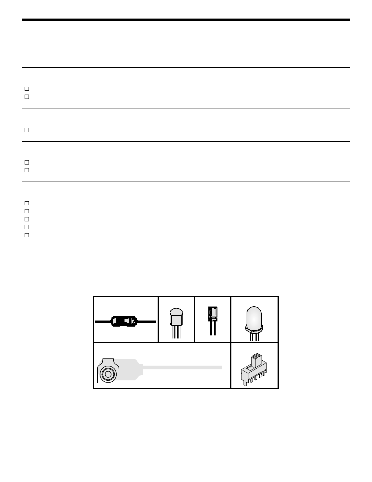
Resistor
Capacitor
PARTS IDENTIFICATION
Electrolytic
SwitchBattery Snap
Transistor LED

-2-
IDENTIFYING RESISTOR VALUES
Use the following information as a guide in proper ly identifying the value of resistors.
BAND 1
1st Digit
Color Digit
Black 0
Brown 1
Red 2
Orange 3
Yellow 4
Green 5
Blue 6
Violet 7
Gray 8
White 9
BAND 2
2nd Digit
Color Digit
Black 0
Brown 1
Red 2
Orange 3
Yellow 4
Green 5
Blue 6
Violet 7
Gray 8
White 9
Multiplier
Color Multiplier
Black 1
Brown 10
Red 100
Orange 1,000
Yellow 10,000
Green 100,000
Blue 1,000,000
Silver 0.01
Gold 0.1
Resistance
Tolerance
Color Tolerance
Silver +10%
Gold +
5%
Brown +
1%
Red +2%
Orange +
3%
Green +
.5%
Blue +.25%
Violet +
.1%
BANDS
1
2 Multiplier Tolerance
IDENTIFYING CAPACITOR VALUES
Capacitors will be identified by their capacitance value in pF (picofarads), nF (nanofarads), or µF (microfarads). Most
capacitors will have their actual value printed on them. Some capacitors may have their value printed in the following
manner. The maximum operating voltage may also be printed on the capacitor.
Second Digit
First Digit
Multiplier
Tolerance
The letter M indicates a tolerance of +
20%
The letter K indicates a tolerance of +10%
The letter J indicates a tolerance of +5%
For the No.01234589
Multiply By 1 10 100 1k 10k 100k .01 0.1
Multiplier
Note: The letter “R” may be used at times
to signify a decimal point; as in 3R3 = 3.3
103K
100V
Maximum Working Voltage
The value is 10 x 1,000 = 10,000pF or .01µF 100V
10µF 16V
Abbreviation Means Multiply Unit By Or
p Pico .000000000001 10
-12
n nano .000000001 10
-9
µ micro .000001 10
-6
m milli .001 10
-3
– unit 1 10
0
k kilo 1,000 10
3
M mega 1,000,000 10
6
1,000 pico units = 1 nano unit
1,000 micro units = 1 milli unit
1,000 units = 1 kilo unit
1,000 nano units = 1 micro unit
1,000 milli units = 1 unit
1,000 kilo units = 1 kilo unit
METRIC UNITS AND CONVERSIONS

-3-
START-UP STAGE
Looking at the schematic diagram (on page 6) shows that the circuit is essentially
symmetrical. There are two transistors, capacitors, LEDs and resistors. These
components are wired exactly the same. If all of the components were exactly
the same, then this circuit could not work. In reality, the components’ tolerances
are different. When the power is turned ON, one branch will conduct faster than
the other. This causes the slower branch to turn OFF. Let’s assume transistor
Q1 conducts first and therefore LEDs D1 and D3 turn ON as shown in Figure 2.
The collector voltage of Q1 immediately goes slightly above the emitter voltage,
therefore charging capacitor C2 through resistor R4. The time it takes to charge
capacitor C2 determines the frequency or “blink rate”of the Robot Blinker . In our
case, it takes about 1/4 of a second. As long as C2 is charging, the current
through resistor R4 will produce a negative voltage at the base of transistor Q2,
keeping this transistor turned OFF.
CONTINUOUS CYCLE STAGE
We’ve learned that as long as C2 is charging, the current through R4 will keep
transistor Q2 OFF. When C2 is near full charge, the current through R4 will
reduce, causing the voltage at the base of Q2 to rise to .7V above its emitter.
This begins to turn transistor Q2 ON. At this moment, the collector voltage of Q2
drops and capacitor C1 begins to charge. The current through R1 produces a
negative voltage at the base of Q1, causing a rapid shutdown fo Q1 and a rapid
turn ON of Q2.
The process now repeats itself with Q2 conducting until capacitor C1 nears full charge and begins to turn
transistor Q1 ON. Effectively the two tr ansistors will alternately turn ON and OFF every 1/2 second. The voltage
on the collector will form a square wave as shown in Figure 3. Whenever the voltage goes negative, a current
will flow in the two associated LEDs and light will be emitted.
B1
R2
Q1
S1
R1
D1
D3
C2
Figure 2
Figure 3
Q1
Q2
0
0
+
+
1/2
sec
R4
INTRODUCTION
The Robot Blinker alternately flashes a pair of LEDs (light emitting diode) on at about two blinks per second. The
circuit is basically an astable multivibrator or free-running oscillator. In analyzing how it works, we will look at the
start-up stage and then at the continuous cycle stage where the LEDs flash at a continuous two cycles per
second.
COMPONENT OPERATION
Let’s first review the operation of critical components. A light emitting diode (LED) is a device that emits light
whenever a current passes through it. The more the current, the brighter the light. See Figure 1, resistor R2 is
placed in series with the LED to limit the current to the desired amount.
An NPN transistor is a device that amplifies and controls the current. It consists
of three elements: Base, Emitter, and Collector. The emitter is connected to a
negative voltage and the collector to a positive voltage. The base controls the
collector-emitter, the collector will conduct current to the emitter when the
voltage across the base-emitter junction is .7V. This current is many times the
base emitter current and therefore the transistor is said to be amplifying the
current. A capacitor is a device that stores current and a resistor is a device that
limits current.
Figure 1
LED
9V
R2

-4-
Introduction
The most important factor in assembling your K-17 Robot Blinker Kit is good soldering techniques. Using the
proper soldering iron is of prime importance. A small pencil type soldering iron of 25 - 40 watts is
recommended.The tip of the iron must be kept clean at all times and well tinned.
Safety Procedures
• Wear eye protection when soldering.
•
Locate soldering iron in an area where you do not have to go around it or reach over it.
• Do not hold solder in your mouth. Solder contains lead and is a toxic substance. Wash your hands
thoroughly after handling solder.
• Be sure that there is adequate ventilation present.
Assemble Components
In all of the following assembly steps, the components must be installed on the top side of the PC board unless
otherwise indicated. The top legend shows where each component goes. The leads pass through the
corresponding holes in the board and are soldered on the foil side.
Use only rosin core solder of 63/37 alloy.
DO NOT USE ACID CORE SOLDER!
CONSTRUCTION
Solder
Soldering Iron
Foil
Solder
Soldering Iron
Foil
Component Lead
Soldering Iron
Circuit Board
Foil
Rosin
Soldering iron positioned
incorrectly.
Solder
Gap
Component Lead
Solder
Soldering Iron
Drag
Foil
1. Solder all components from
the copper foil side only.
Push the soldering iron tip
against both the lead and
the circuit board foil.
2. Apply a small amount of
solder to the iron tip. This
allows the heat to leave the
iron and onto the foil.
Immediately apply solder to
the opposite side of the
connection, away from the
iron. Allow the heated
component and the circuit
foil to melt the solder.
1. Insufficient heat - the
solder will not flow onto the
lead as shown.
3. Allow the solder to flow
around the connection.
Then, remove the solder
and the iron and let the
connection cool. The
solder should have flowed
smoothly and not lump
around the wire lead.
4.
Here is what a good solder
connection looks like.
2. Insufficient solder - let the
solder flow over the
connection until it is
covered. Use just enough
solder to cover the
connection.
3. Excessive solder - could
make connections that you
did not intend to between
adjacent foil areas or
terminals.
4. Solder bridges - occur
when solder runs between
circuit paths and creates a
short circuit. This is usually
caused by using too much
solder. To correct this,
simply drag your soldering
iron across the solder
bridge as shown.
What Good Soldering Looks Like
A good solder connection should be bright, shiny,
smooth, and uniformly flowed over all surfaces.
Types of Poor Soldering Connections

Figure B
Mount the transistor on the position shown.
Make sure that the flat side of the transistor
agrees with the flat side of the marking on the
PC board.
ASSEMBLE COMPONENTS TO THE PC BOARD
-5-
Figure A
Mount the LED with the flat side in the
same direction as marked on the PC
board.
D2 - LED (see Figure A)
R3 - 330Ω 5% 1/4W Resistor
(orange-orange-brown-gold)
Q1 - 2N3904 Transistor
(see Figure B)
R1 - 10kΩ 5% 1/4W Resistor
(brown-black-orange-gold)
C2 - 100µF Electrolytic Cap.
(see Figure C)
D3 - LED (see Figure A)
D1 - LED (see Figure A)
R2 - 330Ω 5% 1/4W Resistor
(orange-orange-brown-gold)
Q2 - 2N3904 Transistor
(see Figure B)
R4 - 10kΩ 5% 1/4W Resistor
(brown-black-orange-gold)
C1 - 100µF Electrolytic Cap.
(see Figure C)
D4 - LED (see Figure A)
Figure C
Electrolytic capacitors have polarity.
Mount the capacitor with the positive
lead in the hole marked (+) on the PC
board.
Polarity
Marking
(--)
(+)
Flat
Flat
S1 - Slide Switch - Cut two 4”
wires and strip 1/2” of insulation
off of both ends of the wires.
Solder a wire to the middle lug
and the other wire to one of the
other lugs. Inser t the other ends
into the PC board. Solder and cut
off the excess leads.
B1 - Battery Snap - Install the
red wire into the positive (+) hole
and the black wire into the
negative (–) hole as shown. Bend
the leads to hold the battery snap
in place. Solder and cut off the
excess leads.
RedBlack

-6-
TROUBLESHOOTING
Consult your instructor or contact Elenco Electronics if you have any problems. DO NOT contact your place of
purchase as they will not be able to help you.
One of the most frequently occurring problems is poor solder connections.
a) Tug slightly on all parts to make sure that they are indeed soldered.
b) All solder connections should be shiny. Resolder any that are not.
c) Solder should flow into a smooth puddle rather than a round ball. Resolder any connection that has
formed into a ball.
d) Have any solder bridges formed? A solder br idge may occur if you accidentally touch an adjacent foil
by using too much solder or by dragging the soldering iron across adjacent foils. Break the bridge with
your soldering iron.
The LEDs will not light
1. Use a fresh 9 volt battery.
2. Check to see that the battery snap is correctly mounted to the PC board.
3. Check to see that the LEDs are mounted correctly. Short the cathode of LED D1 to the negative (--) battery
lead. The LED should light. If not, it is then in backwards or defectiv e. Do the same with LED D3.Both LEDs
should light up. Repeat with LEDs D2 and D4.
4. If the LEDs still don’t light, check the battery snap wiring. The wires must be as shown in the assembly
diagram. Be sure that resistors R2 and R3 are the correct values (330Ω).
5. Check transistors Q1 and Q2. Be sure that they are in correctly. The flat side should be in the direction as
shown in the pictorial diagram.
6. Check the switch S1. Short the lugs of S1 with the two wires. If the LEDs light, the switch is not good.
The LEDs will not blink
1.
If only one pair of LEDs light, then check the transistor whose LEDs are not lit. Replace if necessary.
2. If all four LEDs are lit, then check to see if capacitors C1 & C2 and resistors R1 & R4 have been installed
correctly.
SCHEMATIC DIAGRAM

QUIZ
1. The Robot Blinker circuit is essentially _________________.
2. The LED emits light when ____________ passes through it.
3. The transistor has three elements, name them: _____________, ____________, ____________.
4. The collector voltage must be ________ in respect to the emitter voltage.
5. For the transistor to conduct, the base must be about _____ volts above the emitter.
6. When transistor Q1 is conducting capacitor C2 will be ____________.
7. When transistor Q2 is conducting LEDs D__ and D__ will be on.
8. The frequency of the Robot Blinker is ___ cycles per second.
9. When transistor Q2 is ON, transistor Q1 is _____.
10. Resistors R2 and R3 are used to ________ the current in the LEDs.
Answers: 1. oscillator; 2. current; 3. base, emitter, collector;
4. above; 5. 0.7; 6. charging; 7. 2,4; 8. two; 9. off; 10. limit
Elenco Electronics, Inc.
150 W. Carpenter Aven ue
Wheeling, IL 60090
(847) 541-3800
http://www.elenco.com
e-mail: elenco@elenco.com
 Loading...