

Page 1
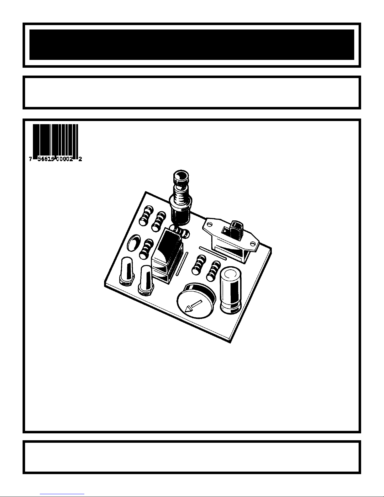
SPACE WAR GUN KIT
MODEL K-10
Assembly and Instruction Manual
Elenco Electronics, Inc.
Copyright © 1989 Elenco Electronics, Inc. Revised 2001 REV-H 753210A
Page 2
CAPACITORS
Qty Symbol Description Part #
2 C2, C3 .01µF Discap (103) 241031
1 C1 220µF Electrolytic 282244
SEMICONDUCTORS
Qty Symbol Description Part #
1 IC1 LM556 Integrated Circuit 330556
1D1
LED (Light Emitting Diode) Red
350002
1D2
LED (Light Emitting Diode) Green
350010
MISCELLANEOUS
Qty Symbol Description Part #
1 PC Board 518010
1 S1 Switch Push Button 540001
1 S2 Switch Slide 541102
1 Solder Roll 24” 551124
1 B1 Batter y Snap 9V 590098
1 SPK1 Speaker 8Ω 590102
1 IC Socket 14-pin 664014
2 Wire 4” Blue 814620
PARTS LIST
Contact Elenco Electronics (address/phone/e-mail is at the back of this manual) if any parts are missing or
damaged. DO NOT contact your place of purchase as they will not be able to help you.
RESISTORS
Qty Symbol Description Color Code Part #
1R5 47Ω 5% 1/4W yellow-violet-black-gold 124700
2 R1, R2 100Ω 5% 1/4W brown-black-brown-gold 131000
1 R6 560Ω 5% 1/4W green-blue-brown-gold 135600
1R3 1kΩ 5% 1/4W brown-black-red-gold 141000
1 R4 56kΩ 5% 1/4W green-blue-orange-gold 155600
1 P1 Tr im Pot 50kΩ 191552
-1-
Resistor Transistor
Capacitor
Push Button
PARTS IDENTIFICATION
Electrolytic
Speaker
Integrated Circuit
Switch
Discap
LED
Trim Pot
Battery Snap
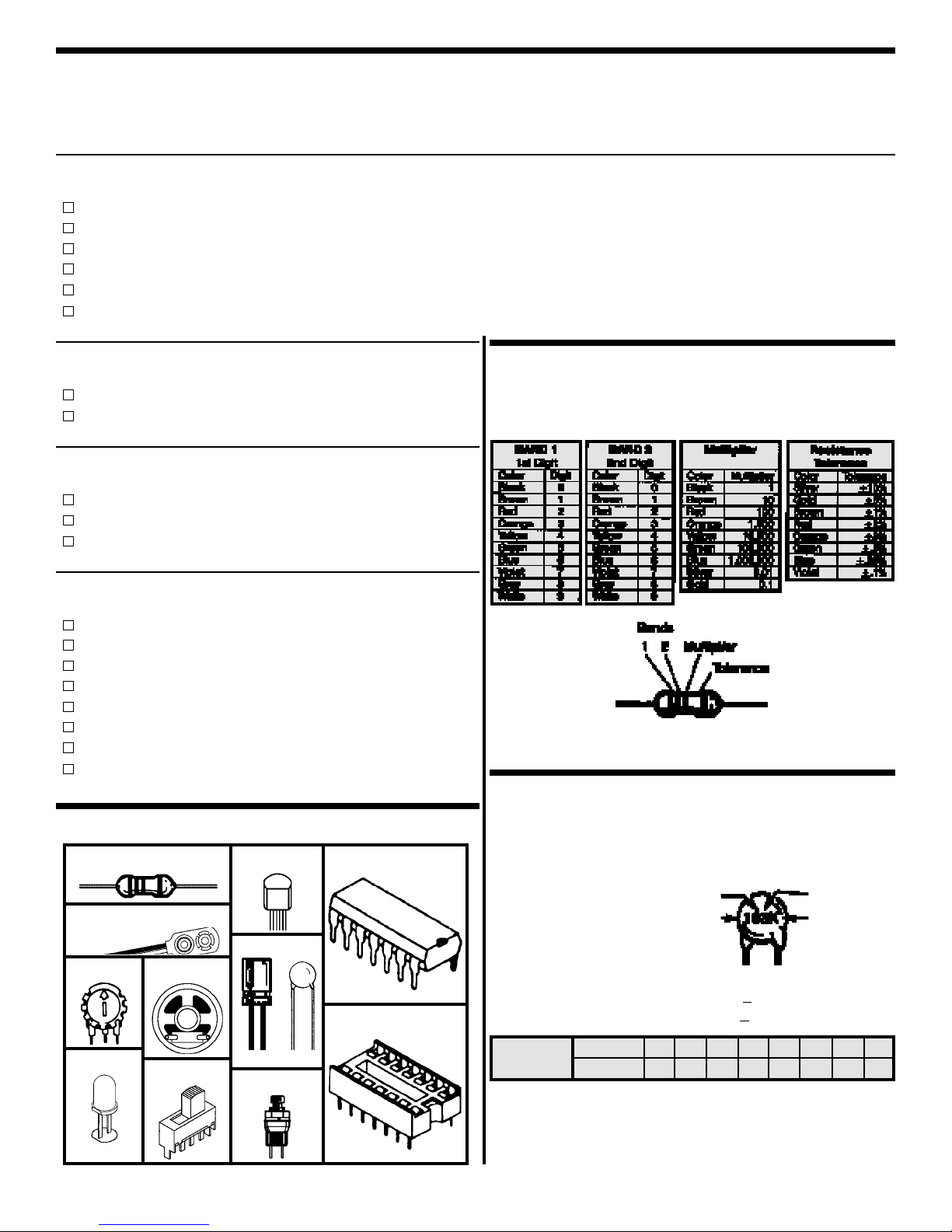
IDENTIFYING RESISTOR VALUES
Use the following information as a guide in properly
identifying the value of resistors.
IDENTIFYING CAPACITOR VALUES
Capacitors will be identified by their capacitance value in
pF (picofarads), nF (nanofarads), or µF (microfarads).
Most capacitors will have their actual value printed on
them. Some capacitors may have their value printed in the
following manner.
Second Digit
First Digit
Multiplier
Tolerance
The above value is 10 x 1,000 = 10,000pF or .01µF
The letter K indicates a tolerance of +
10%
The letter J indicates a tolerance of +5%
For the No. 01234589
Multiply By 1 10 100 1k 10k 100k .01 0.1
Multiplier
Note: The letter “R” may be used at times to
signify a decimal point; as in 3R3 = 3.3
IC Socket
Page 3
-2-
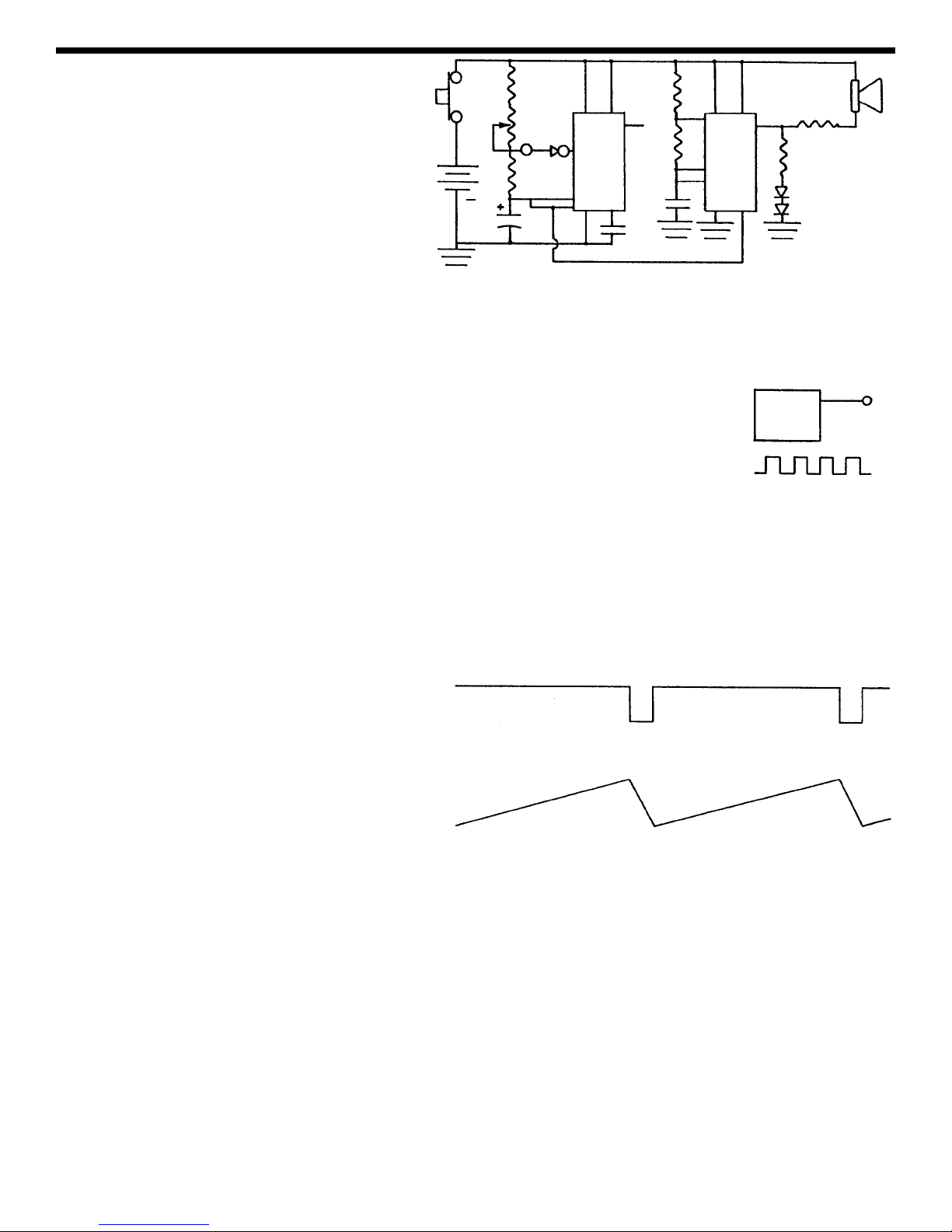
CIRCUIT OPERATION
Figure 1 shows the circuit of the Space War
Gun. It consists of two 555 integrated circuits
(IC) packaged in one IC 556. A 555 timer is well
known for its ability to operate as an astable
multivibrator oscillator. This oscillator can put
out a square wave or pulses depending on the
value of the resistors. The first 555A IC
oscillates at about 2000 cycles per second. The
555A IC drives the 555B IC to give the weird
space sounds.
THE 555 IC TIMER
Let’s study the right side of Figure 1 which shows the 555B circuit. Resistor R3, R4 and
capacitor C3 control the frequency of oscillation of this circuit. Capacitor C3 charges
through resistors R3 and R4, but discharges through resistor R4 and the IC. Since the
value of R3 and R4 are 1kΩ and 56kΩ respectively, their total value equals 57kΩ. Thus,
C3 charges through 57kΩ and discharges through 56kΩ. The charge and discharge time
is about equal. The output at pin 5 will be a square wave as shown in Figure 2. The
frequency of oscillation will be around 2,000 cycles per second. If a speaker is connected
to output pin 5, we will hear the 2,000 cycle tone. When the two LEDs are connected to
this output, they will light whenever the output goes positive. Resistor R6 is added to limit
the current in the LEDs. Resistor R5 is added to limit the current in the speaker.
The operation of the 555A IC differs quite a bit from the 555B IC . Note the v alue of the capacitor C1, it is 220µF
or 22,000 times bigger than the .01µF used in the 555B. This means that the frequency of oscillation will be
much lower. Also, resistor P1 is made a 50,000Ω variable. Resistor R2 is only 100Ω. Thus, the charge time
on capacitor C1 is through the 100Ω. With the pot at the maximum position, the charge to discharge will be
500:1. Figure 3A shows the pulse as it appears in
the output in 9. Figure 3B shows the voltage across
capacitor C1. By varying the value of P1, the
distance between the pulses will be made shorter of
the frequency will be increased. At the minimum
position, the charge time will be twice the discharge
time (200Ω versus 100Ω). Thus, varying P1 will
change the frequency between .1 cycles to 45
cycles. This change in frequency adds to the effects
of the Space War Gun.
VOLTAGE CONTROLLED OSCILLATOR (VCO)
The 555 timer is designed to allow the output frequency to be varied by changing the DC voltage. If we raise
the voltage at the 555B input pin 3, the output will decrease in frequency. In the Space Gun design, the VCO
of the 555B is connected to the voltage across capacitor C1. This voltage is sawtooth in shape as shown in
Figure 3B. As this voltage increases, the pitch-frequency of the 555B timer is constantly changing at a rate
determined by the voltage amplitude of the 555A timer.
Figure 2
Figure 3B
Figure 3A
Clock Circuit
555
Output
5
Low
R1
S1
P1
S2
R2
8
13
C1
B1
9V
12
7
11
C2
555A 555B
410
9
N.C.
R4
C3
2
7
6
1
R3
14510
R5
R6
D1
D2
3
SPK
+
Figure 1
Page 4

Introduction
The most important factor in assembling your K-10 Space War Gun Kit is good soldering techniques. Using the
proper soldering iron is of prime importance. A small pencil type soldering iron of 25 - 40 watts is
recommended.The tip of the iron must be kept clean at all times and well tinned.
Safety Procedures
• Wear eye protection when soldering.
•
Locate soldering iron in an area where you do not have to go around it or reach over it.
• Do not hold solder in your mouth. Solder contains lead and is a toxic substance. Wash your hands
thoroughly after handling solder.
• Be sure that there is adequate ventilation present.
Assemble Components
In all of the following assembly steps, the components must be installed on the top side of the PC board unless
otherwise indicated. The top legend shows where each component goes. The leads pass through the
corresponding holes in the board and are soldered on the foil side.
Use only rosin core solder of 63/37 alloy.
DO NOT USE ACID CORE SOLDER!
CONSTRUCTION
Solder
Soldering Iron
Foil
Solder
Soldering Iron
Foil
Component Lead
Soldering Iron
Circuit Board
Foil
Rosin
Soldering iron positioned
incorrectly.
Solder
Gap
Component Lead
Solder
Soldering Iron
Drag
Foil
1. Solder all components from
the copper foil side only.
Push the soldering iron tip
against both the lead and
the circuit board foil.
2. Apply a small amount of
solder to the iron tip. This
allows the heat to leave the
iron and onto the foil.
Immediately apply solder to
the opposite side of the
connection, away from the
iron. Allow the heated
component and the circuit
foil to melt the solder.
1. Insufficient heat - the
solder will not flow onto the
lead as shown.
3. Allow the solder to flow
around the connection.
Then, remove the solder
and the iron and let the
connection cool. The
solder should have flowed
smoothly and not lump
around the wire lead.
4.
Here is what a good solder
connection looks like.
2. Insufficient solder - let the
solder flow over the
connection until it is
covered. Use just enough
solder to cover the
connection.
3. Excessive solder - could
make connections that you
did not intend to between
adjacent foil areas or
terminals.
4. Solder bridges - occur
when solder runs between
circuit paths and creates a
short circuit. This is usually
caused by using too much
solder. To correct this,
simply drag your soldering
iron across the solder
bridge as shown.
What Good Soldering Looks Like
A good solder connection should be bright, shiny,
smooth, and uniformly flowed over all surfaces.
Types of Poor Soldering Connections
-3-
Page 5

-4-
ASSEMBLE COMPONENTS TO THE PC BOARD
R5 - 47Ω 5% 1/4W Resistor
(yellow-violet-black-gold)
C3 - .01µF (103) Discap
D1 - LED Diode Red
(see Figure A)
R6 - 560Ω 5% 1/4W Resistor
(green-blue-brown-gold)
D2 - LED Diode Green
(see Figure A)
IC1 - IC Socket 14-pin
IC1 - 556 Integrated Circuit
(see Figure B)
J1 - Jumper Wire
J2 - Jumper Wire
(see Figure C)
P1 - Trim Pot
C1 - 220µF Electrolytic Capacitor
(see Figure D)
Figure D
Electrolytic capacitors
have polarity. Be sure
to mount them with
the negative (--) lead
(marked on side) in
the correct hole.
Polarity
Marking
SPK1 - Speaker
Strip 1/8” of insulation off of both ends of
the 4” wires. Solder a wire to each lug of
the speaker and then insert the other end
of the wires through the hole in the PC
board as shown. Solder the wires in the
position shown on the top legend. Cut off
the excess leads.
R4 - 56kΩ 5% 1/4W Resistor
(green-blue-orange-gold)
R3 - 1kΩ 5% 1/4W Resistor
(brown-black-red-gold)
S1 - Push Button Switch
B1 - Battery Snap -
Insert the red
and black wire through the hole in the
PC board as shown. Install the red
wire into the positive (+) hole and the
black wire into the negative (--) hole.
Solder and cut off the excess leads.
S2 - Slide Switch
J3 - Jumper Wire (see Figure C)
R1 - 100Ω 5% 1/4W Resistor
(brown-black-brown-gold)
R2 - 100Ω 5% 1/4W Resistor
(brown-black-brown-gold)
C2 - .01µF (103) Discap
Figure A
Mount the LED onto
the PC board with the
flat side of the LED in
the same direction as
marked on the PC
board.
Flat
Figure B
Insert the IC socket into the PC
board with the notch in the direction
shown on the top legend. Solder the
IC socket into place. Insert the IC
into the socket with the notch in the
same direction as the notch on the
socket.
Notch
Figure C
Use an excess lead to
form a jumper wire.
Bend the wire to the
correct length and
mount it to the PC
board.
Foil Side of PC Board
Page 6

COMPONENT CHECK
1. Be sure that all components have been mounted in their correct places.
2. Make sure that C1, the electrolytic capacitor is mounted correctly. The negative lead should be in the hole
as shown on the top legend.
3. Have LEDs D1 and D2 been installed correctly? The flat side of their bodies should be in the same direction
as marked on the top legend. If the LEDs are in backwards, they will not light.
4. Pay close attention to the red and black wires of the batter y snap. The red wire should be installed in the
positive (+) hole and the black wire in the negative (--) hole. Snap in a fresh 9-volt battery.
TROUBLESHOOTING
Contact Elenco Electronics if you have any problems. DO NOT contact your place of purchase as they will not
be able to help you.
1. One of the most frequently occurring problems is poor solder connections. Tug slightly on all parts to make
sure that they are indeed soldered.
2. All solder connections should be shiny. Resolder any that are not.
3. Solder should flow into a smooth puddle rather than a round ball. Resolder any connection that has formed
into a ball.
4. Have any solder bridges formed? A solder bridge may occur if you accidentally touch an adjacent foil by
using too much solder or by dragging the soldering iron across adjacent foils. Break the bridge with your
soldering iron.
SCHEMATIC DIAGRAM
-5-
S1
B1
+
+
C1
220µF
7
11
3
8
12
S2
13
R2
100Ω
R1
100Ω
P1
50kΩ
4
10 14
R3
1kΩ
1
2
6
5
9
IC1
556
R4
56kΩ
SPK1
R5
47Ω
R6
560Ω
.01µF .01µF
C2
C3
D1
D2
Page 7

-6-
QUIZ
1. The Space War Gun has two ____________ _____________ oscillators.
2. Capacitor C3 and resistors R3 and R4 controls the _____________ of oscillation.
3. The charge time of capacitor C3 is through resistors ______ and ______.
4. The discharge of capacitor C3 is through resistor ______ and the ______.
5. The 555B timer operates at a __________ frequency than the 555A timer.
6. Increasing the value of capacitor C2 will ___________ the frequency of oscillation.
7. Increasing the voltage of VCO pin 3 of the 555B timer will __________ the frequency of oscillation.
8. VCO stands for ____________ ____________ _____________.
9. In the Space War Gun design, the 555A timer controls the frequency of the _____________ timer.
10. Resistor R6 is added to ___________ the current in the LEDs.
Answers: 1. astable multivibrator; 2. frequency; 3.R3, R4; 4. R4, IC; 5.higher; 6. lower;7. decreases; 8. voltage controlled oscillator;9. 555B; 10. limit
Build This Great Kit and
Learn How Cassette Players Work
Easy-to-build kit teaches you basic mechanical and electronic circuits. You will
have fun building this kit and learn how a tape player works. Lesson manual
teaches magnetic recording and audio amplifier theory, speed control, mechanical
switching, and much more. Comes complete with all parts including Stereo Head
Phones. Clear plastic case allows you to show your friends your accomplishments.
Requires two (2) “AA” batteries (not included).
Stereo Cassette Player Kit
with T raining Course
Model AK-200
Simple and fun to build, compact,
portable, and adds safety to your home
or office. Learn the basics of motion
detector technology while building this
motion detector kit that uses a
pyroelectric infrared sensor. Comes
complete with all parts, PC board,
case, schematic, and extensiv e tr aining
manual. Requires one (1) 9V battery
(not included).
Uses: • Sentry • Burglar Alarm
• Message Minder • Room Detector
Super Sensor Motion Detector Kit
with Training Course Model AK-510
This deluxe strobe light makes learning fun
and easy. You will have fun building this kit
and learn how strobe lights work. Comes
complete with all components and lesson
manual. Kit uses high energy xenon flash
tube. Learn about transistors, oscillators,
step-up transformers, trigger circuits, flash
tubes, and more! Easy-to-follow
instructions include lesson manual and
self-test. Requires two (2) “C” batteries
(not included).
Strobe Light Kit
with Training Course Model AK-520
Requires soldering iron and cutters (not included in kits)
• Easy-to-follow assembly manual • Lessons and self tests included
• Transparent Case • Includes Headphones
• High Resolution • Belt Clip
The AK-700 is a push button
electronic telephone. It is equipped
with the following features:
Pulse/tone dialing, automatic
redial, a ringer turn off switch, 4
neon bulbs for visual indication of
telephone ringing, clear seethrough case to show the total
inner workings of the phone.
Sectionalized construction and
testing makes construction easy.
Wall mounting cradle included.
Telephone Kit
with Training Course Model AK-700
Page 8

Elenco Electronics, Inc.
150 W. Carpenter Avenue
Wheeling, IL 60090
(847) 541-3800
http://www.elenco.com
e-mail: elenco@elenco.com
 Loading...