

Page 1
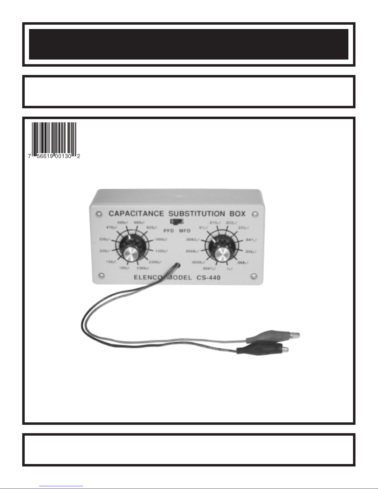
CAPACITANCE SUBSTITUTION BOX
MODEL CS-440 / K-38
Assembly and Instruction Manual
ElencoTMElectronics, Inc.
Copyright © 1989 ElencoTMElectronics, Inc. Revised 2003 REV-I 753440
Page 2
The Capacitance Substitution Box is a convenient instrument in determining the desired capacitance values in
circuits under design or test. The values selected for your capacitance substitution box were determined to be
the most commonly used in modern solid-state circuits. The values are from 100pF to .1mF in 24 steps.
PARTS LIST
If you are a student, and any parts are missing or damaged, please see instructor or bookstore.
If you purchased this capacitance box kit from a distributor, catalog, etc., please contact Elenco
(address/phone/e-mail is at the back of this manual) for additional assistance, if needed.
CAPACITORS
Qty. Symbol Description Part #
1 R1 100pF (101) 50V 221017
1 R2 150pF (151) 50V 221510
1 R3 220pF (221) 50V 222210
1 R4 330pF (331) 50V 223317
1 R5 470pF (471) 50V 224717
1 R6 560pF (561) 50V 225610
1 R7 680pF (681) 50V 226880
1 R8 820pF (821) 50V 228210
1 R9 1000pF (102) 50V 231035
1 R10 1500pF (152) 50V 231516
1 R11 2200pF (222) 50V 232216
1 R12 3300pF (332) 50V 233310
1 R13 .0047mF (472) 50V 234710
1 R14 .0056mF (562) 100V 235618
1 R15 .0068mF (682) 50V 236810
1 R16 .0082mF (822) 100V 238218
1 R17 .01mF (103) 100V 241017
1 R18 .015mF (153) 100V 241517
1 R19 .022mF (223) 100V 242217
1 R20 .033mF (333) 100V 243317
1 R21 .047mF (473) 100V 244717
1 R22 .056mF (563) 100V 245618
1 R23 .068mF (683) 100V 246818
1 R24 .1mF (104) 100V 251017
TM
Electronics
Qty. Description Part #
1 PC Board 517007
1 PC Mount Switch 541103
2 12 Position Switch 542013
2 Knob 622009
1 Case w/ Cover and Screws 62CS440
2 Nut 9mm 644102
2 Washer 9mm x 15mm 645103
1 Alligator Clip Black 680001
1 Alligator Clip Red 680002
12” Wire Black Stranded 814210
12” Wire Red Stranded 814215
1 Solder Tube 9ST4
MISCELLANEOUS
-1-
Page 3
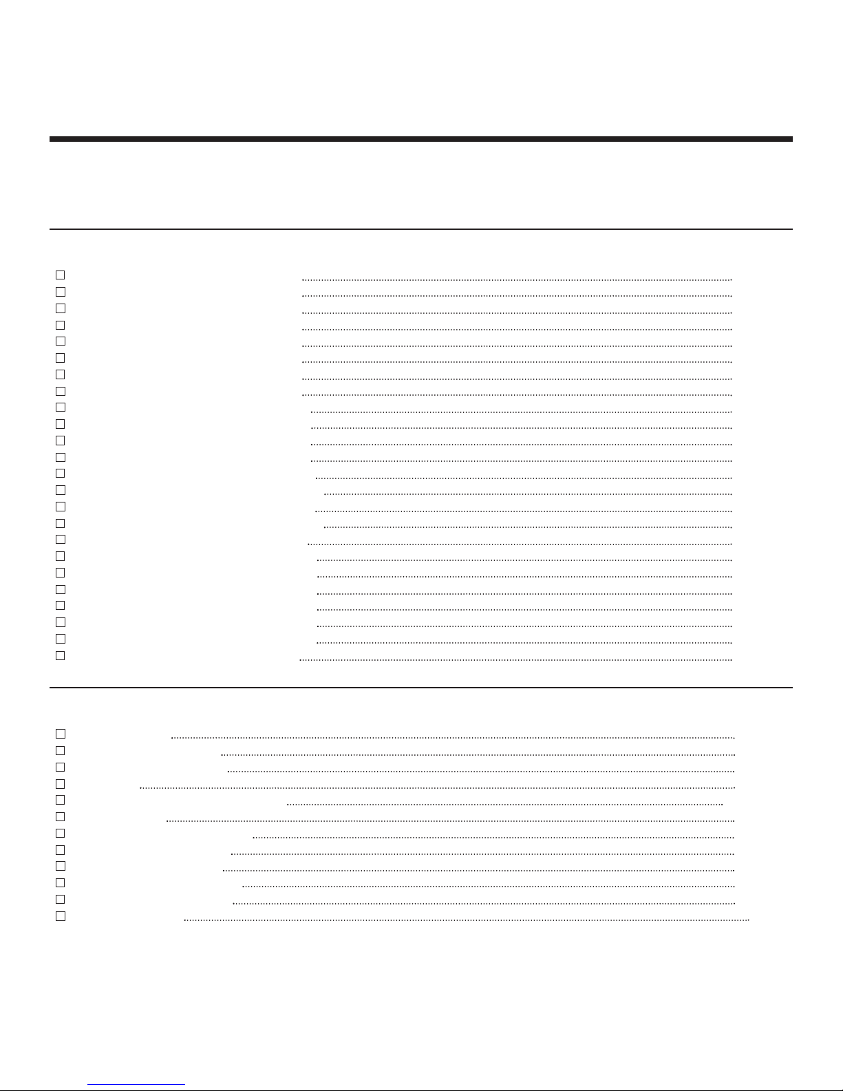
PARTS IDENTIFICATION
Switch PC Mount
Switch 12 Position
9mm Nut
PC Board
Capacitor
Washer
Alligator Clip
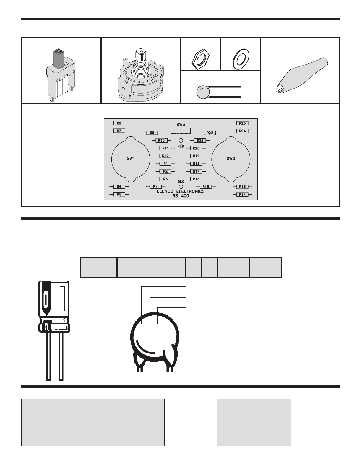
IDENTIFYING CAPACITOR VALUES
Capacitors will be identified by their capacitance value in pF (picofarads), nF (nanofarads), or mF (microfarads). Most
capacitors will have their actual value printed on them. Some capacitors may have their value printed in the following
manner. The maximum operating voltage may also be printed on the capacitor.
For the No.01234589
Multiplier
10mF 16V
Multiply By 1 10 100 1k 10k 100k .01 0.1
First Digit
Note: The letter “R” may be used at times
to signify a decimal point; as in 3R3 = 3.3
Second Digit
Multiplier
103K
100V
Tolerance
The letter M indicates a tolerance of +
The letter K indicates a tolerance of +10%
The letter J indicates a tolerance of +5%
20%
Maximum Working Voltage
The value is 10 x 1,000 = 10,000pF or .01mF 100V
METRIC UNITS AND CONVERSIONS
Abbreviation Means Multiply Unit By Or
p Pico .000000000001 10
n nano .000000001 10
m micro .000001 10
m milli .001 10
– unit 1 10
k kilo 1,000 10
M mega 1,000,000 10
-12
-9
-6
-3
0
3
6
-2-
1. 1,000 pico units = 1 nano unit
2. 1,000 nano units = 1 micro unit
3. 1,000 micro units= 1 milli unit
4. 1,000 milli units = 1 unit
5. 1,000 units = 1 kilo unit
6. 1,000 kilo units= 1 mega unit
Page 4

CONSTRUCTION
Introduction
The most important factor in assembling your CS-440 Capacitance Substitution Box Kit is good soldering
techniques. Using the proper soldering iron is of prime importance. A small pencil type soldering iron of 25 40 watts is recommended. The tip of the iron must be kept clean at all times and well tinned.
Safety Procedures
• Wear eye protection when soldering.
Locate soldering iron in an area where you do not have to go around it or reach over it.
•
• Do not hold solder in your mouth. Solder contains lead and is a toxic substance. Wash your hands
thoroughly after handling solder.
• Be sure that there is adequate ventilation present.
Assemble Components
In all of the following assembly steps, the components must be installed on the top side of the PC board unless
otherwise indicated. The top legend shows where each component goes. The leads pass through the
corresponding holes in the board and are soldered on the foil side.
Use only rosin core solder of 63/37 alloy.
DO NOT USE ACID CORE SOLDER!
What Good Soldering Looks Like
A good solder connection should be bright, shiny,
smooth, and uniformly flowed over all surfaces.
1. Solder all components from
the copper foil side only.
Push the soldering iron tip
against both the lead and
the circuit board foil.
2. Apply a small amount of
solder to the iron tip. This
allows the heat to leave the
iron and onto the foil.
Immediately apply solder to
the opposite side of the
connection, away from the
iron. Allow the heated
component and the circuit
foil to melt the solder.
3. Allow the solder to flow
around the connection.
Then, remove the solder
and the iron and let the
connection cool. The
solder should have flowed
smoothly and not lump
around the wire lead.
4.
Here is what a good solder
connection looks like.
Component Lead
Foil
Solder
Foil
Solder
Foil
Soldering Iron
Circuit Board
Soldering Iron
Soldering Iron
Types of Poor Soldering Connections
1. Insufficient heat - the
solder will not flow onto the
lead as shown.
2. Insufficient solder - let the
solder flow over the
connection until it is
covered. Use just enough
solder to cover the
connection.
3. Excessive solder - could
make connections that you
did not intend to between
adjacent foil areas or
terminals.
4. Solder bridges - occur
when solder runs between
circuit paths and creates a
short circuit. This is usually
caused by using too much
solder. To correct this,
simply drag your soldering
iron across the solder
bridge as shown.
Rosin
Soldering iron positioned
incorrectly.
Solder
Component Lead
Solder
Soldering Iron
Foil
Gap
Drag
-3-
Page 5

ASSEMBLY INSTRUCTIONS
Begin the PC board assembly with the 100pF capacitor placed in position R1. Be sure to
identify the correct value. Bend the leads to fit. Place the capacitor into the PC board with
the leads coming out on the copper foil side. Solder into place and clip off the excess
leads.
R9 - 1000pF (102) 50V Cap.
R7 - 680pF (681) 50V Cap.
R8 - 820pF (821) 50V Cap.
R10 - 1500pF (152) 50V Cap.
R11 - 2200pF (222) 50V Cap.
R12 - 3300pF (332) 50V Cap.
R1 - 100pF (101) 50V Cap.
R2 - 150pF (151) 50V Cap.
R3 - 220pF (221) 50V Cap.
R5 - 470pF (471) 50V Cap.
R6 - 560pF (561) 50V Cap.
R4 - 330pF (331) 50V Cap.
R22 - .056mF (563) 100V Cap.
R24 - .1mF (104) 100V Cap.
R23 - .068mF (683) 100V Cap.
R21 - .047mF (473) 100V Cap.
R20 - .033mF (333) 100V Cap.
R19 - .022mF (223) 100V Cap.
R18 - .015mF (153) 100V Cap.
R17 - .01mF (103) 100V Cap.
R16 - .0082mF (822) 100V Cap.
R14 - .0056mF (562) 50V Cap.
R13 - .0047mF (472) 100V Cap.
R15 - .0068mF (682) 50V Cap.
-4-
Page 6

SW3 - PC Mount Switch
SW1
Mount SW3 in the place shown on the PC board.
Solder into place.
Red Test Lead
Black Test Lead
Cut off 1 1/2” of wire off of both the red and black
wires (SAVE them for later use). Strip 1/4” of
insulation off both ends of the 10 1/2” red and black
wires and insert them into the holes as marked on
the PC board. Solder into place. Tie a knot with
both wires 1 1/2” from the surface of the PC board
as shown in Figure 1. Pull the wires through the
hole in the cover. Slide the alligator boots onto the
wires. Solder the wires to the alligator clips. Then,
slide the boots onto the clips.
SW2
Bend the tab on the switches
down (see Figure 2). Attach the
two switches loosely to the front
panel with the 9mm nuts and
washers. Line up the holes of
the PC board with the switch
lugs, as shown in Figure 3. Be
sure that the board lays flat,
then solder the lugs into place.
Tighten down the 9mm nuts.
Washer
9mm Nut
Figure 3
Bend Tab Over
Figure 2
PC Board
Cover
Bend Tabs
Over Wire
Figure 1
Wiper Pin
Jumper wire from SW1
Jumper wire from SW2
Strip 1/4” of insulation off of both ends of the 1 1/2”
red and black wires. Solder one end of the wire to the
wiper pin on the 12 position switches and the other to
the pad without a hole, as shown in Figure 4.
Installation of Knobs if Capacitance Meter is
Available
Place the knobs loosely on the switch posts. Push
the slide switch to the PFD position. Connect a
capacitance meter to the output. Line up the pointer
of the knob with the value shown on your meter, then
push the knob onto the shaft. Push the slide switch
to the MFD position and repeat the same procedure.
Jumper Wires
Wiper Pin
SW2
SW1
Figure 4
-5-
Page 7

Installation of Knobs without Capacitance Meter
If a capacitance meter is not available, turn both
switches so that the wiper contact is in the position
shown in Figure 5. Start with switch SW1, follow the
copper run on the PC board from the lug in contact
with the wiper to the 680pF (R7) capacitor, to be
sure that the switch is set in the proper position.
Align the knob on the SW1 (PFD) switch to the
680pF position, push the knob onto the shaft.
Follow the same procedure for switch SW2 (MFD),
except follow the copper run to the .0047mF (R13)
capacitor. Align the knob on the SW2 (MFD) switch
to the .0047mF position.
TESTING THE CIRCUIT
LugPC Board
Wiper Contact
Figure 5
SW1 PFD POSITION
Value Position Meter Reading
100pF
150pF
220pF
330pF
470pF
560pF
680pF
820pF
1000pF
1500pF
2200pF
3300pF
SW2 MFD POSITION
Value Position Meter Reading
.0047mF
.0056mF
.0068mF
.0082mF
.01mF
.015mF
.022mF
.033mF
.047mF
.056mF
.068mF
.1mF
Note: Capacitors being tested have a 10% tolerance. Because of lead capacitance from the alligator clips to
the PC board, all values will read 30pF +10pF above the actual capacitance value.
SCHEMATIC DIAGRAM
-6-
Page 8

ElencoTMElectronics, Inc.
150 W. Carpenter Avenue
Wheeling, IL 60090
(847) 541-3800
http://www.elenco.com
e-mail: elenco@elenco.com
 Loading...